Lunar Additive Base (LAB)

Hello! My name is Oliver and I’m a senior in high school in Vancouver, Canada. I’ve been working with CAD modelling for almost five years now through my own experimentation and through my school’s drafting program. With aspirations to become an engineer in the future, I took a very engineering-forward mindset to this project. I focused heavily on the practicality of the materials used, construction methods, and everyday usability to elevate the realism of my design. Enjoy!
Supplies
SOFTWARE
- Fusion 360
- Twinmotion
- Bambu Studio
- Adobe Fresco
- Notability
PHYSICAL MODEL
- Foam core
- 3D printer
- PLA filament
- White, grey, black spray paint
- Cardboard box
- Quick-dry concrete
- Putty knife
- Lemon
- Charcoal
- Baking flour
- blanket
- phone camera
- tripod
- Printer
- Paper
- Toothpick
DEFINING THE MISSION
I’ve always carried an interest in space, making the choice for the location of my project simple: the moon! However, instead of trying to design a singular moon base, I took a different perspective. I decided to try and answer the question “what would the habitats in a moon colony look like?”. To answer this question, I determined a set of guidelines for moon colony structures that formed the basis of my design.
Overall, the most important factor in any extraterrestrial design is efficiency. When you’re on the moon, there’s no room for excess. Every part should serve a purpose, and it must do so without failure.
Design Principles:
1. Primarily uses materials indigenous to the construction location: Bringing materials to the moon is physically and financially difficult. Rocket payload capacities are not very large and each kilogram brought to the moon can cost upwards of $1 million. Using materials already on the moon embraces the landscape to solve both these issues.
2. Minimize materials used: While there is no shortage of building materials on the moon, extracting the necessary resources is still a costly process. Minimizing the materials used lowers the individual construction costs, allowing for a larger and more prosperous lunar colony.
3. Minimize human labor: Human labour is particularly difficult on the moon because of the lack of mobility in space suits. To minimize human labour, designs should be simple to construct, and take full advantage of prefabrication and automation construction techniques.
Additional Requirements
- Houses four people
- Structure is moderately comfortable
NOTE: My design relies on some assumptions about human technological advancement. These include improvements to robotics, rockets, and non-planar 3D printing. It also relies on having some human establishment already on the moon, such as a small outpost.
DESIGN BRIEF

My design is the Lunar Additive Base or LAB, intended to be the foundation of humanity’s first lunar colony. The LAB is a 3D printed lunar habitat designed to be easily and repeatedly constructed at a low cost. It embraces the moon’s unique resources to built at scale as it primarily uses materials found on the lunar surface. The exterior structure is an octagonal, ring-like building roughly 8 metres in diameter and constructed using a large 3D printer. This printer extrudes lunarcrete, a material akin to concrete that can be made using readily available lunar resources. On top of the structure is a thick layer of lunar soil to block solar radiation. The interior is optimized to include all necessary life support systems while retaining enough room for up to four humans to comfortably live. The LAB is simple to build and easily repeatable. It utilizes the landscape to improve living and create humanity’s first lunar colony.
IDEATION
To develop the ideas for this project, I relied heavily on the criteria I established in the design requirements. First I worked on the exterior structure of the LAB. I went through several, iterations of foot prints, wall cross sections, and support structures until I figured out my final design. Based off my exterior structure plan, I developed several different floor plan.
EXTERIOR STRUCTURE
PRINTER
3D printing buildings is a relatively new concept that is slowly being deployed on Earth, however there are already several organizations and companies working to adapt the idea for extraterrestrial applications. See here: https://www.esa.int/Enabling_Support/Space_Engineering_Technology/Building_a_lunar_base_with_3D_printing
The printer used to construct the LAB is comprised of an extruder head mounted to a cylindrical robotic arm. This arm can be easily assembled by astronauts and has a 4 metre span. The arm is able to withstand the high torques associated with this specially long span due to the use of lightweight materials and the reduced gravitational force on the moon.

The material extruded by the printer is called Lunarcrete. Lunarcrete is a concrete-like substance first proposed in 1985 by Larry A. Beyer. Regular concrete has three main ingredients: aggregate, cement, and water. Lunarcrete aggregate would be made of regolith (lunar soil) and the cement would be made from refined lunar rocks. To save on water, the water could be substituted for sulphur, which can be extracted from certain moon rocks. For an in-depth look: https://smad.com/wp-content/uploads/2023/01/VOL.05-BEYER.pdf
FOOTPRINT
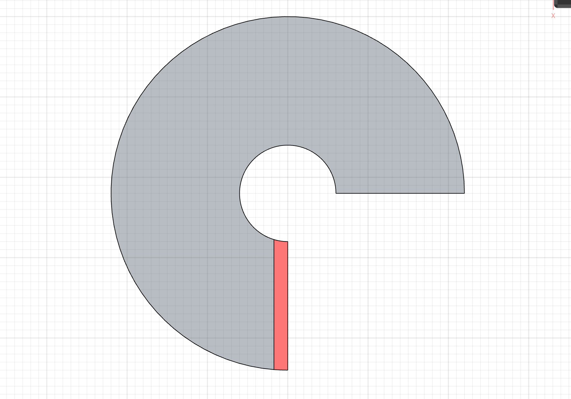
The footprint of the LAB is defined by the 3D printer. The largest structure the printer can create is a donut around itself. There is also a quarter cut-out to allow the printer to be removed and reused. While this donut shape does provide the most internal floor space, much of this space is unusable due to the curved walls.
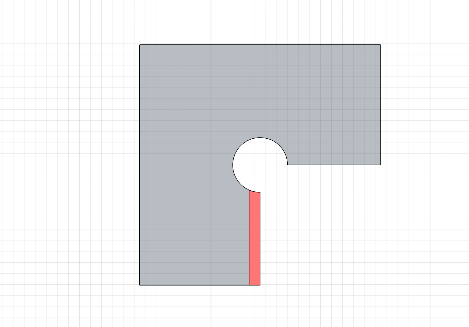
This issue can be solved by squaring off the footprint to create flat walls. All the walls become easily usable, however a great deal of floor space is sacrificed as this option has just 62% the total area of the donut.
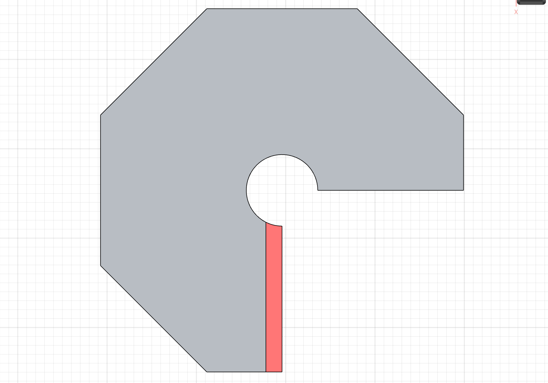
Combining both solutions, an octagonal footprint can be used. This option has the flat, usable walls, while also keeping 90% of the floor space.
WALL CROSS SECTION
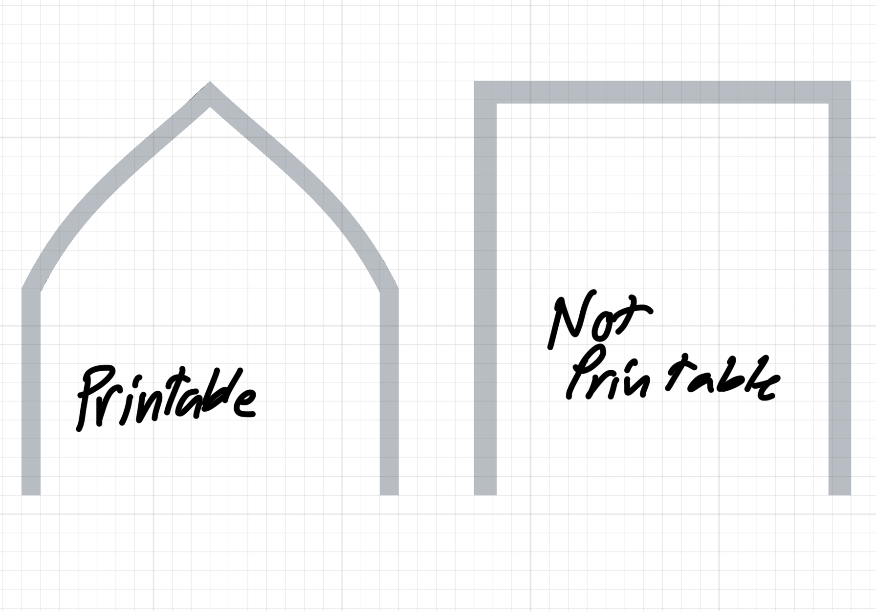
The cross section of the walls and ceiling of the structure is another unique design challenge brought up by using 3D printing. Fused Deposition Modelling (FDM) printers like the one used in this project work by extruding horizontal layers on top of each other to form a 3D body. The main difficulty with this printing method is overhangs, which occur when there is no material below to extrude on top of. FDM printers can print angled walls, however larger overhangs require temporary support structures.

Support structures are not viable for this design as they use additional material and would require intensive human labour to remove. Instead, the cross section can be designed so that instead of a straight, horizontal ceiling, the walls angle in at a printable angle to form the roof.
INSULATION LAYERS
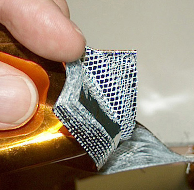
The absence of an atmosphere means the moon takes the full force of the sun’s radiation. Without protection, humans on the moon would be exposed to carcinogenic radiation, as well as temperatures that fluctuate between +120ºC and -120ºC. The thin, printed walls of the structure don’t provide sufficient protection. Modern solutions do exist, like the Multi-Layer Insulation (MLI) used on the International Space Station (ISS). However, MLI is expensive, difficult to install, and doesn’t uses materials indigenous to the lunar surface.
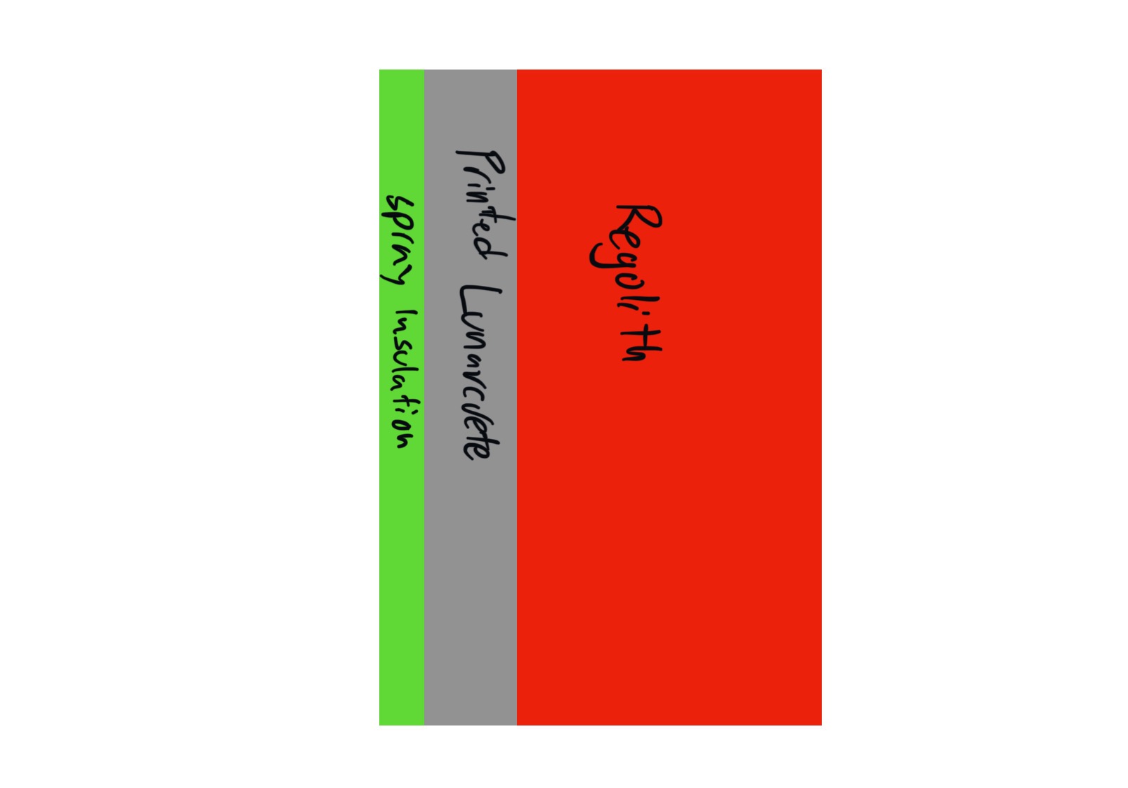
One of the simplest ways to protect against radiation is to create a barrier that is thick and dense. This can be done on the moon by simply piling a layer of lunar regolith on top of the printed structure.
The final layer of insulation is on the inside of the LAB, where a thin layer of spray insulation is applied. This also seals any microscopic holes in the Lunarcrete and regolith layers. This spray would have to be brought from Earth, however, given the relatively small amount required, this would not be a logistical issue.
EXTERIOR LATTICE
The walls of the LAB are intentionally thin at just 5 cm as this minimizes the amount of Lunarcrete used. However, additional structural integrity is required to withstand forces like the piled on regolith. The exterior lattice is printed as part of the walls, and adds additional strength while using only a fraction of the materials as a completely solid wall. This lattice also gives stability to the piled on regolith to prevent slippage.
INTERIOR DESIGN
FLOOR PLAN
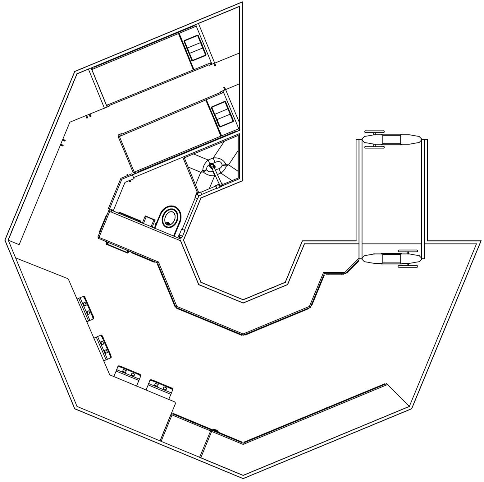
The internal floor plan is optimized to take full advantage of the available space. Every wall is utilized to ensure the inhabitants can live comfortably while still having easy access to all the equipment necessary to live on the moon.
AIRLOCK
At the entrance to structure is the airlock, which can hold two fully suited astronauts. Due to the repeated stress cycles the airlock experiences while in use, this is the largest component that must be brought from Earth.
EVA PREP ZONE
Directly in front of the airlock is the Extravehicular Activity (EVA) Preparation Zone. In this area, all the spacesuits are stored, and there is a large amount of open space to make entering and exiting EVA suits easy.
CENTRALIZED LIFE SUPPORT
Life support systems are a critical component for human survival. The LAB features a central life support hub along the structure’s inner wall. Contained in this hub is the water management, air supply, electrical, and heat regulation systems. The hub location makes accessing it easier and reduces complexity by containing all the habitat’s complex mechanisms in a single region.
To further reduce complexity and increase efficiency, the building does not feature a power supply, water supply, or communication interface. Since these buildings are part of a colony, more efficient centralized systems are instead used, with connections running to each LAB. This drastically reduces the individual building complexity, and leaves more space for other equipment. (Note: the water connection is only an auxiliary connection as almost all water used is recycled by the water management system)
BATHROOM
Bathrooms by nature are complex as they require substantial plumbing. To reduce complexity, the central life support hub, with the water management system inside, is used as one of the walls of the bathroom. Attached to this wall is the toilet and sink, eliminating the need for plumbing to these devices. The only plumbing required is two short pipes running to and from the shower, keeping the overall bathroom complexity to a minimum.
HIGH STORAGE CAPACITY
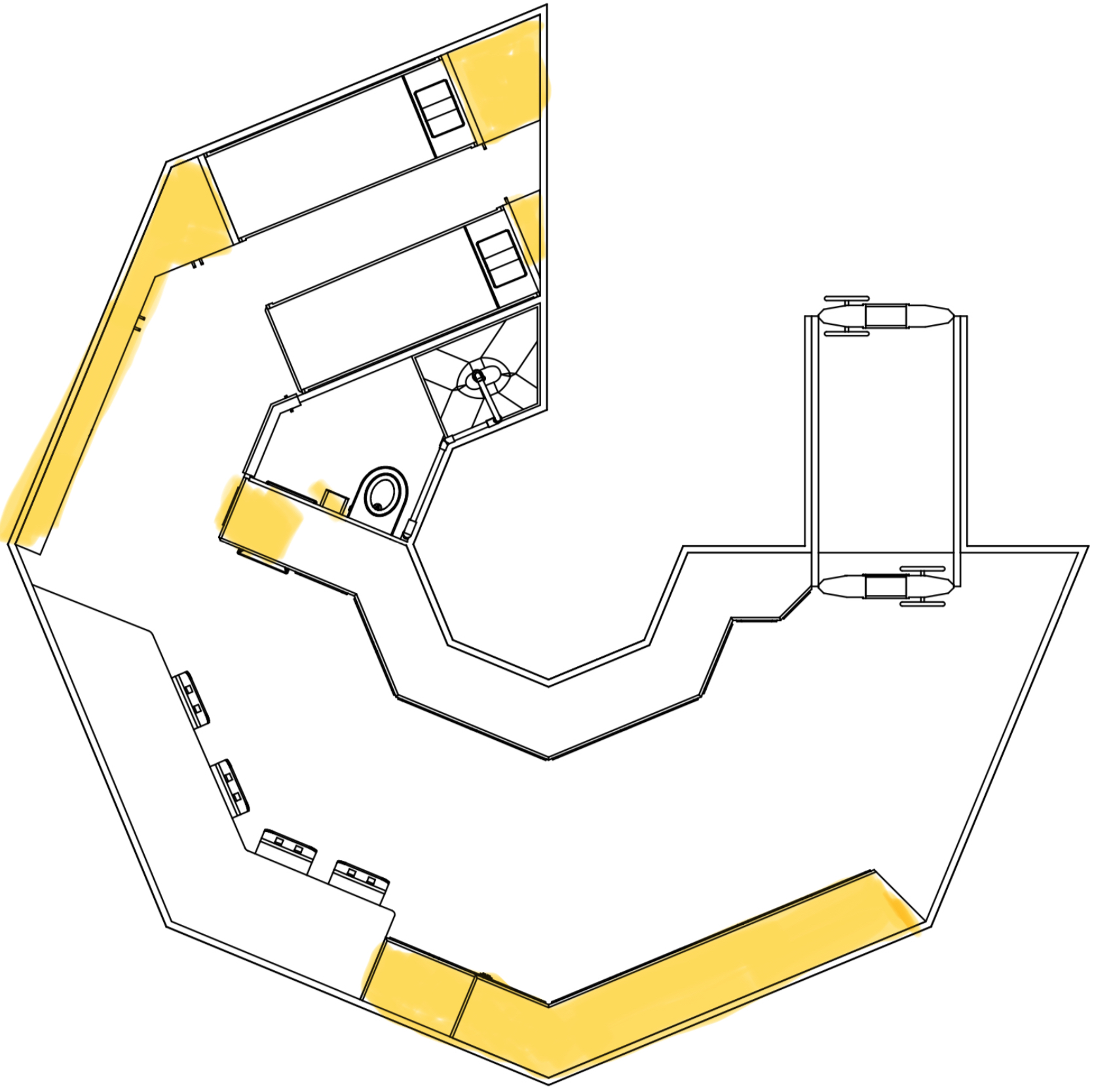
From food, to spare parts, to scientific equipment, living on the moon demands a lot of storage space. Practically every wall is lined with shelves and cupboards to ensure there is enough space to store the necessary equipment.
MULTIPURPOSE SPACE
Also near the center of the structure is the multipurpose space. Here, people can conduct experiments, work, dine, or do any number of other tasks.
EXERCISE EQUIPMENT RACK
Another system vital to the health of the astronauts is the exercise equipment rack. The moon’s lower gravity means the skeletal system of inhabitants is under less load, which may lead to a loss in bone density. To maintain proper health, the exercise equipment rack includes compact tension cables and a flip-out bike to work every part of the body.
CONSTRUCTION PROCESS
The LAB is designed for manufacturing, meaning every component is considered to streamline the construction process.
Step 1: Material and Equipment Shipping
The materials shipped from Earth are the machinery, furniture, life support, printer, rovers, and any other necessary equipment.
Step 2: Land Preparation
The construction site is prepared by removing any rocks and debris to create a flat printing space. This is done by both humans and regolith depositing rovers.
Step 3: Printer and Lunarcrete Mixer Assembly
Astronauts will assemble the printer and Lunarcrete mixer. The rovers will also be deployed to collect regolith for the Lunarcrete and insulation layer.
Step 4: Pre-Print Preparation
Before the printing process commences, some larger components must be installed so that they can be printed around. These components include the airlock and the central racks for the life support systems. The necessary Lunarcrete ingredients are also be added to the mixer.
Step 5: Printing
The Lunarcrete mixer is connected to the printer and the LAB can be printed.
Step 6: Printer Disassembly and Rover Deployment
After the print is complete, the printer is disassembled and removed to be reused for another building. The rovers are also deployed to collect regolith.
Step 7: Insulation
Regolith is deposited by rovers on top of the LAB. The interior is then sprayed with a thin layer of insulation.
Step 8: Life Support Installation
The life support systems, including water management, air supply, electrical, and heat regulation are installed in the central racks. Electrical, auxiliary water, and communication connections are installed, connecting the LAB to the rest of the colony. Once everything is installed, every system is tested, including the first habitat pressurization.
Step 9: Furniture and Equipment
All remaining furniture and equipment is installed, completing the construction process.
EXTERIOR MODELLING IN FUSION 360
WALLS
Step 1: Create a sketch for the wall cross section and foot print of the LAB.
Step 2: Extrude and fillet the edges of the cross section. Then, align this body with the foot print.
Step 3: Use the sweep tool to extrude the cross section along the centreline of the foot print.
Step 4: Add the airlock and use the extrude tool to curve the flat edged walls. Then, use the shell tool to hollow the structure, creating the walls.
LATTICE STRUCTURE
Step 1: Use the offset tool in the surface menu and select the outside faces of the model. Since this lattice is intended to give structural support to the walls with larger overhangs, the edge walls and the airlock should not be selected. Click “OK” to create a new surface body with a width of zero units.
Step 2: Turn off “capture design history”. This gives access to the form tab for later. Then, go into the mesh menu and select the “tessellate” tool. This will convert the surface body into a mesh body. The sliders will change the number of triangles in the mesh, which will affect the quality of the final lattice.
Step 3: Again in the mesh menu, use the “remesh” tool to create a new mesh. The remesh type should be set to “uniform” as this evens the size of the triangles. “Preserve sharp edges” and “preserve boundaries” should be selected, and the sliders here will also change the number of triangles in the mesh.
Step 4: Under the modify tab, use the “convert mesh” tool to convert the mesh back to a surface body.
Step 5: In the form menu, use selection priority to select all the edges of the body. Then, use the pipe tool to create pipes along the selected edges. The sliders can then be used to alter the width and curvature of the pipes. Click “OK”, give it some time to load, and you’re done!
INTERIOR MODELLING IN FUSION 360

Modelling the interior doesn’t require many advanced modelling techniques like the exterior as most of the objects have flat faces. This is intentional as flat faces are much more practical. They are less complex, meaning objects have less parts to be packed and assembled on the lunar surface.
RENDERING

To render my project I used Twinmotion. There are a lot of great rendering softwares out there, however Twinmotion is the one I know how to use best.
My rendering process for this project was quite simple. I first imported my CAD models into Twinmotion from Fusion 360 as an OBJ, retaining all the colours I had applied. Then I added my own textures, edited the landscape to look like the moon, along with a few smaller details.
PHYSICAL MODEL
Step 1: To start the physical modelling process, I first imported the CAD models of the LAB and the Lunarcrete printer into a slicer software. This software converts a 3D model into an instruction set for a 3D printer called G-code. I used Bambu Studio for this step, however basically any slicer software will work just as well.
Step 2: Once the parts were sliced, I sent the G-code to my 3D printer to be printed. The filament I used and recommend for this step is PLA as it’s cheap and easy to print.
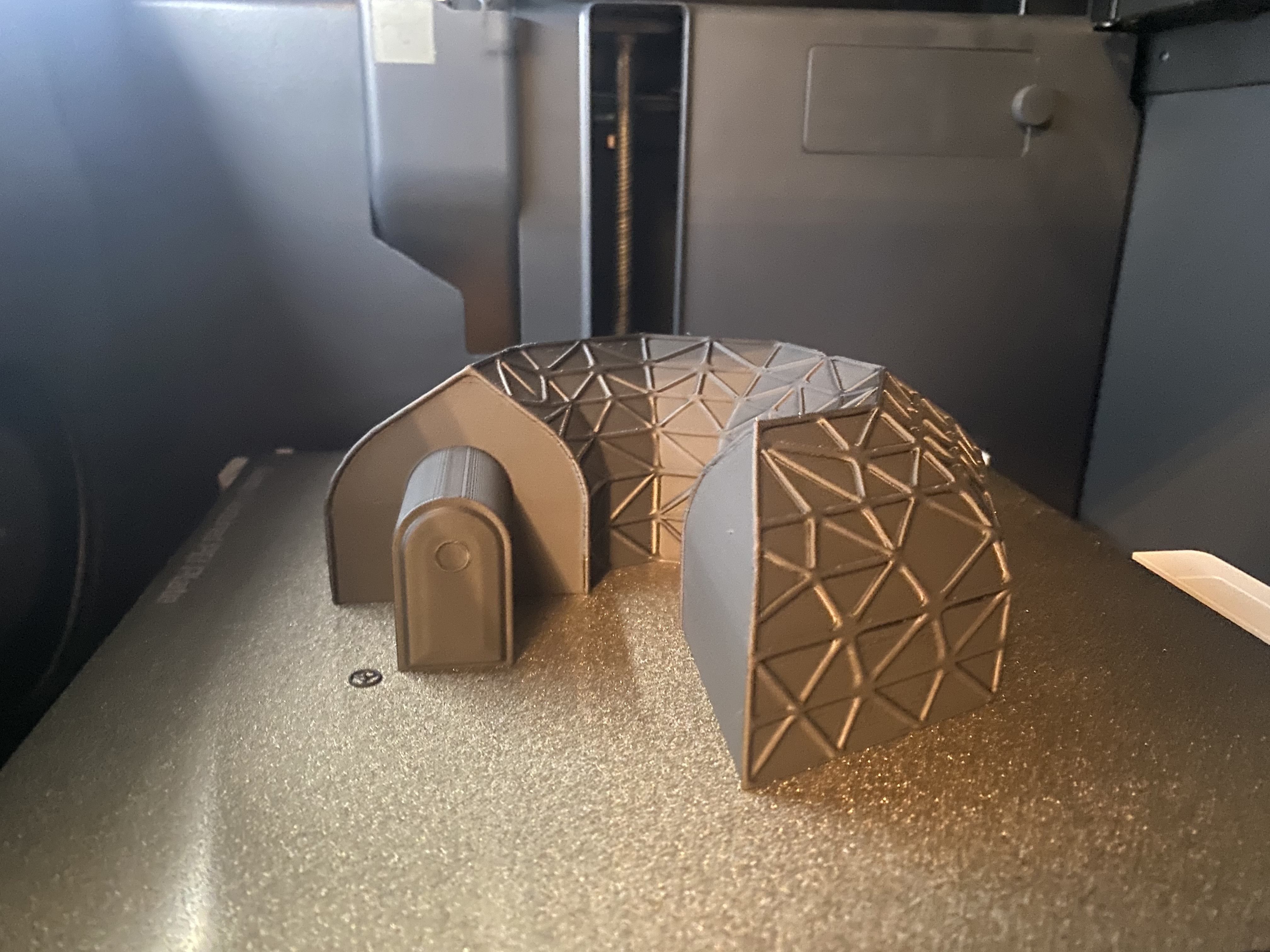
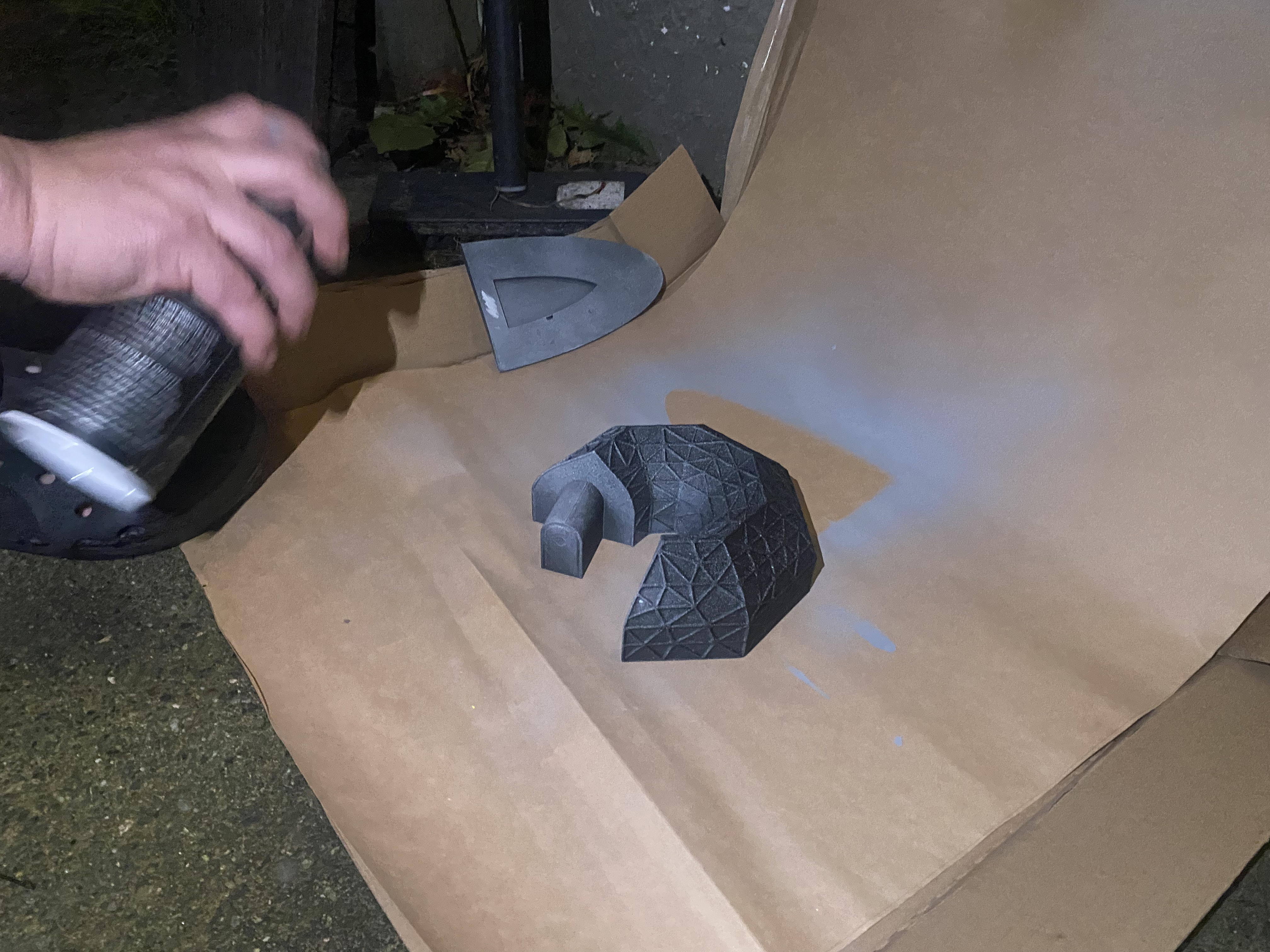
Step 3: I glued together the pieces of printer, and then brought all the 3D printed parts outside to be painted. The LAB model was sprayed with a light grey similar to the colour of the surface of the moon. The printer model was sprayed with white.
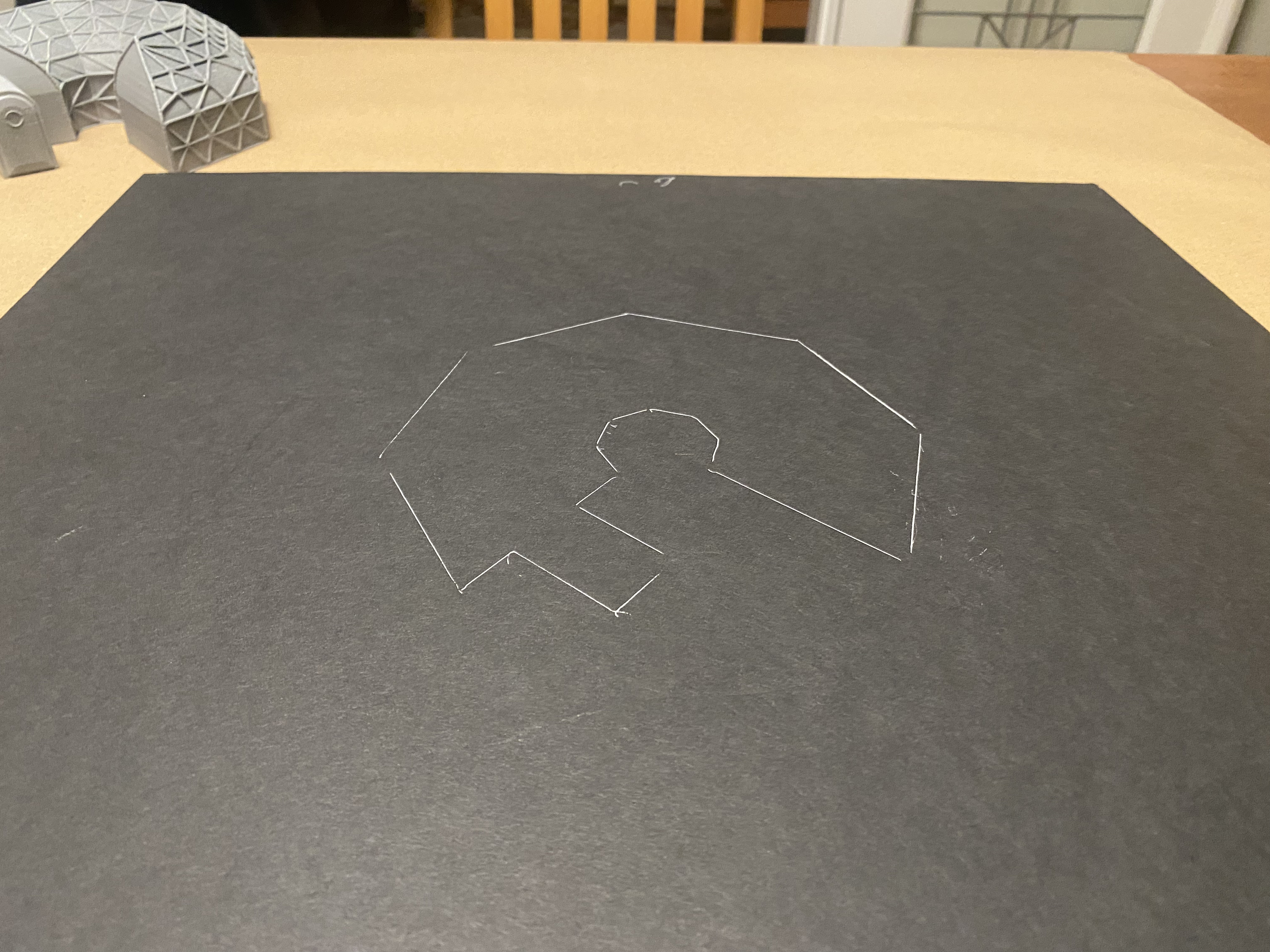
 Step 4: While the paint dried, I moved on to the landscape of the model. To start, I cut the base out of a sheet of black foam core. I then traced the outline of the LAB onto the board.
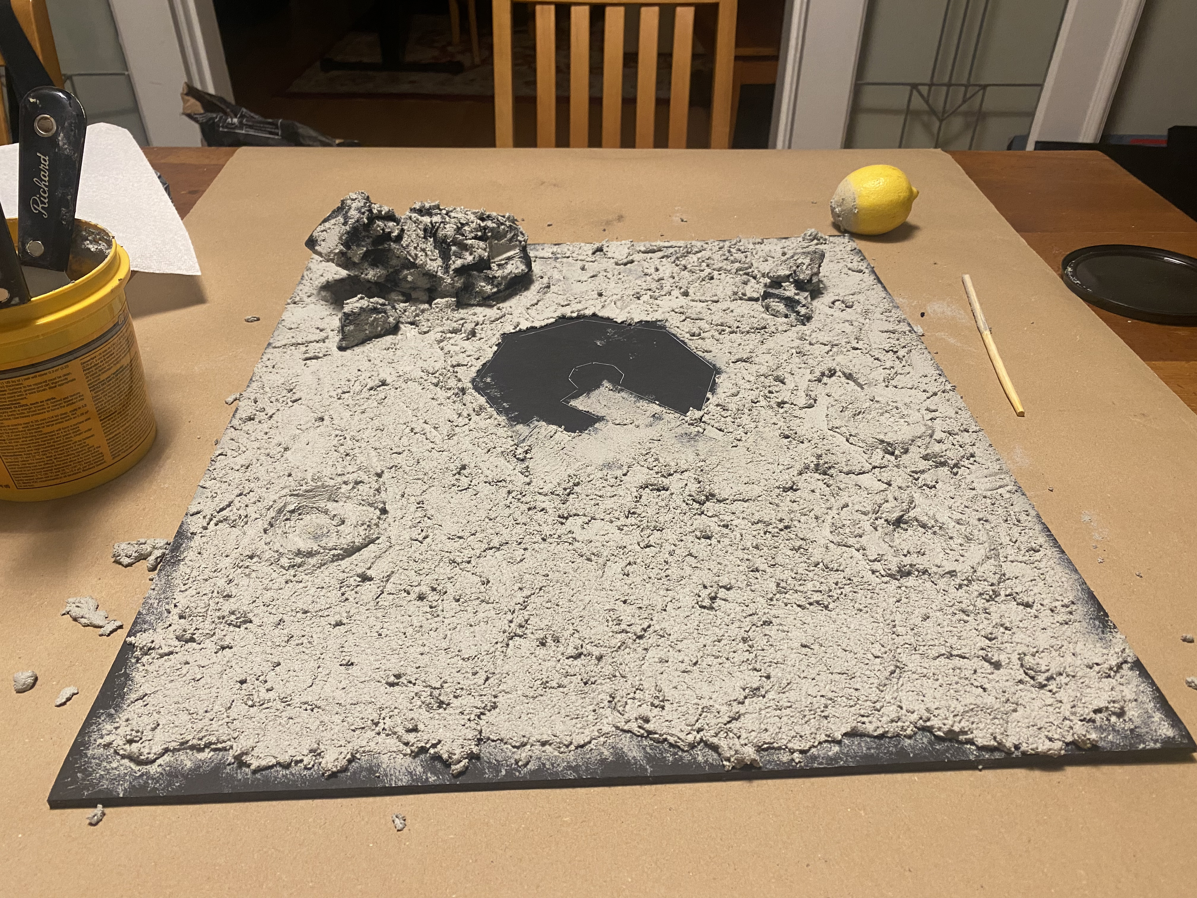
Step 5: This was the fun step! To create the rocky grey landscape of the moon, I used quick-dry concrete. To make the desired texture, I simply loosely spread the concrete around using a putty knife until I was satisfied with the result.
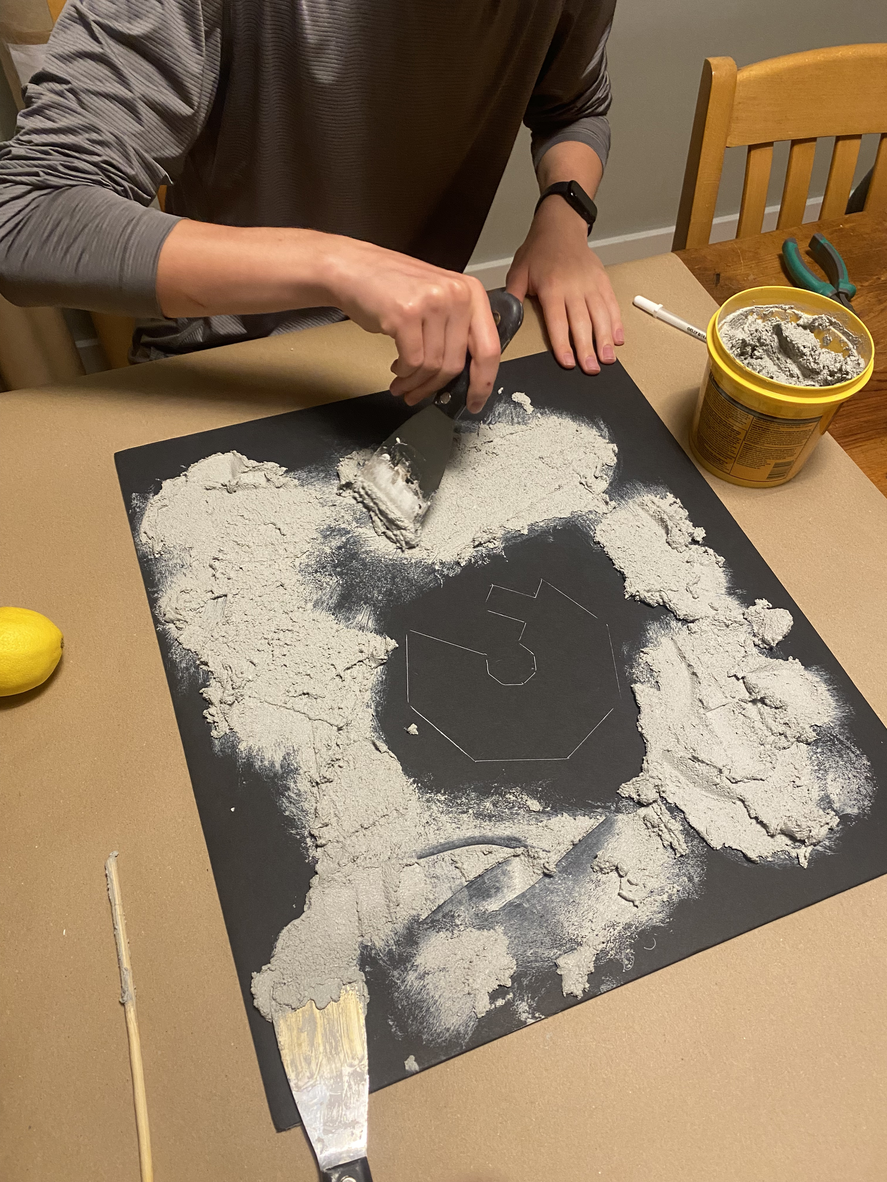
After the initial spread, I added details to the texture. I used an old lemon (though you could really use any dome-shaped object) to form craters. And to add bigger boulders, I covered pieces of charcoal in concrete and stuck them on top.
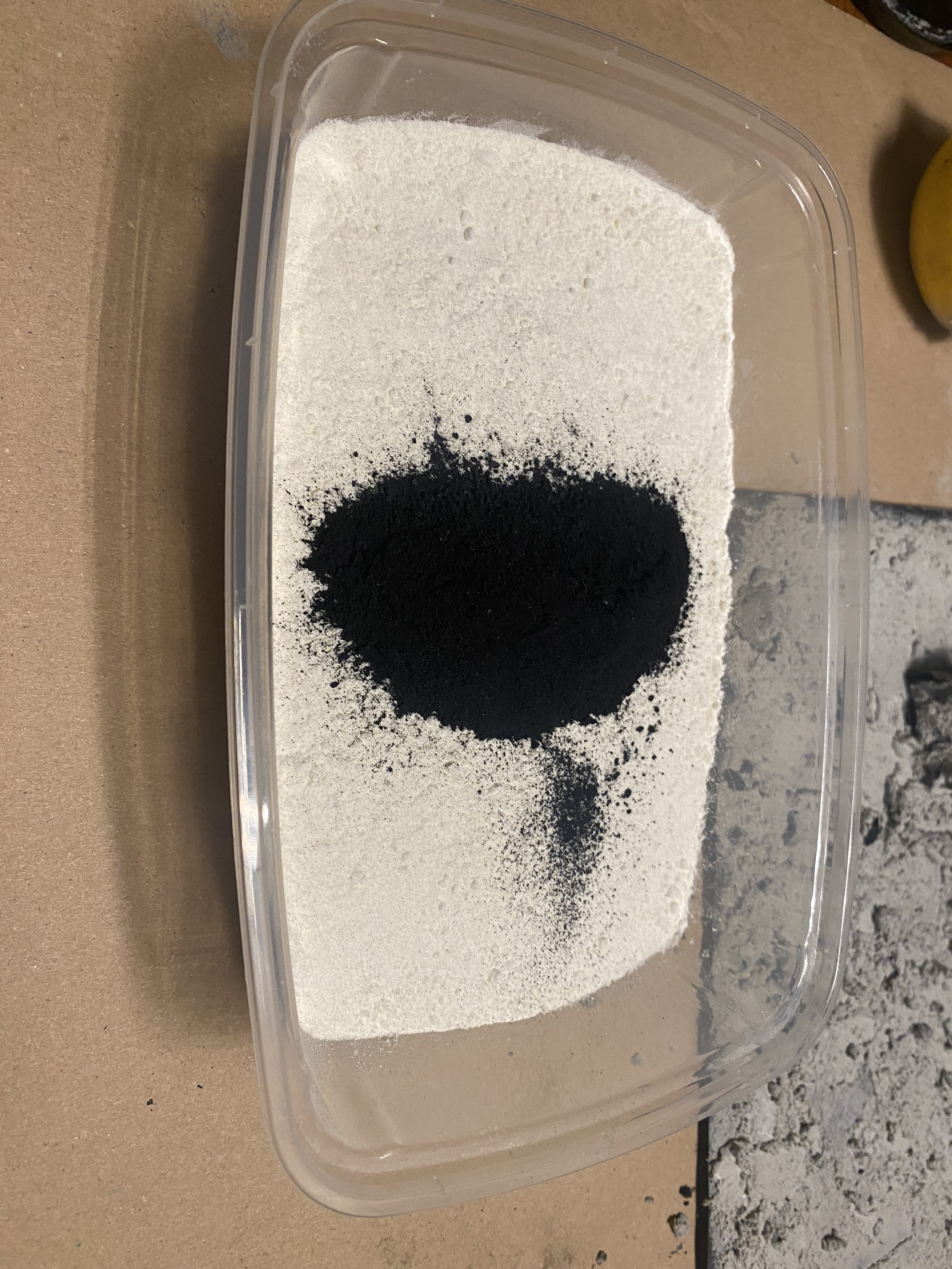
 Step 6: The moon isn’t just rocky terrain though as there is the loose regolith layer on top. To create this, I mixed crushed charcoal with baking flour until the colour matched the concrete.
Step 7: After waiting for the concrete to dry, all the components of the model were complete and ready to be assembled in the photo booth. This model is supposed to be in space, which is notoriously dark. To achieve this effect, I placed the model in a cardboard box with the inside painted black. I also added a cutout of the Earth to the back of the box and made a small Canadian flag for a little national pride.
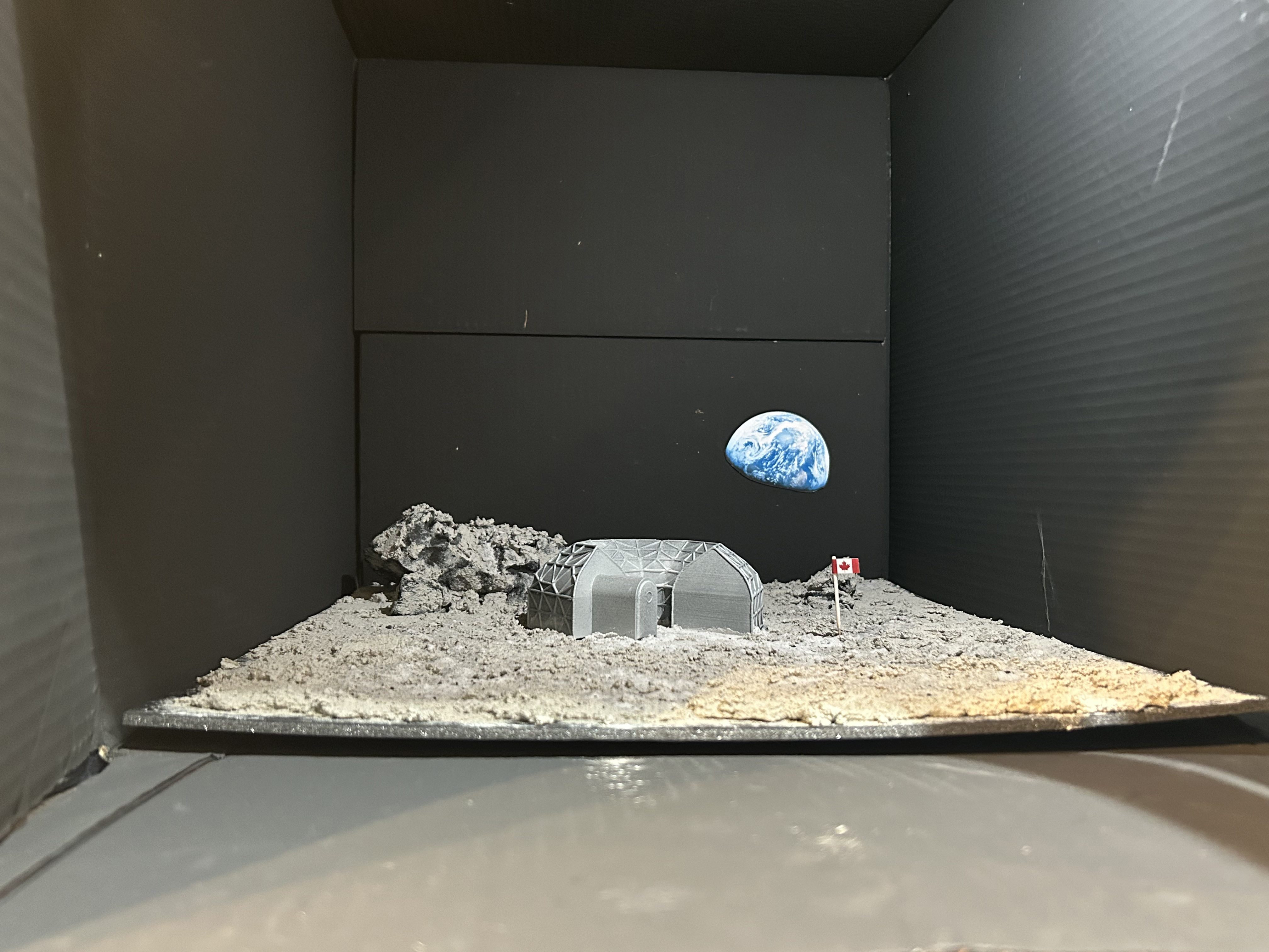
This box actually wasn’t originally created for this project and I was so happy that I could use it again. Instead, I made it back in grade 7 as part of my science fair project on black body radiation. The inside is painted with special paint called Black 2.0 that absorbs a lot of light and has a very nice matte finish.
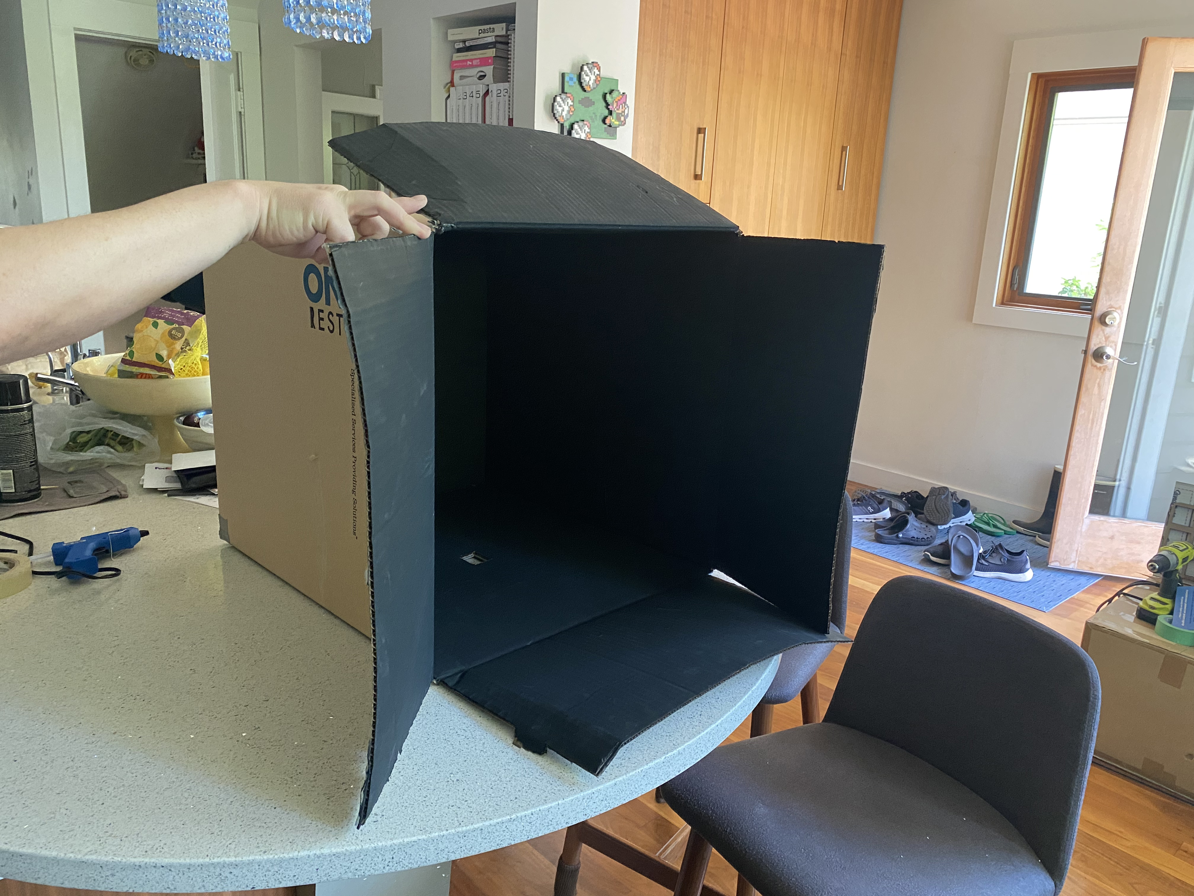
To finish the Photo Booth preparation, I set up a phone camera on a tripod and draped the box in a blanket to make sure no light could get in.
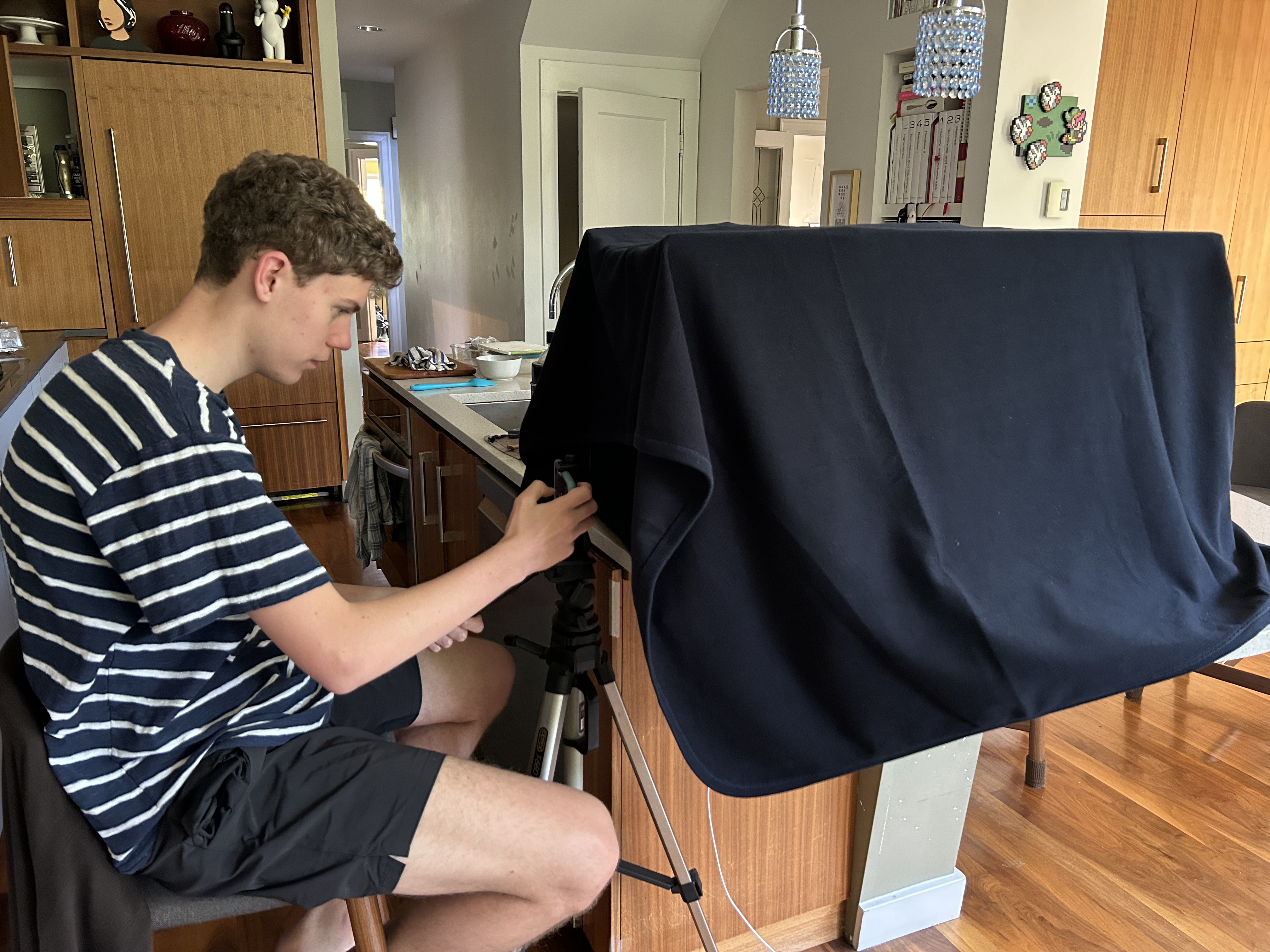
Step 8: With all the pieces assembled and the photo booth ready, I took some shots! To create the shadowed and highlighted lighting effect, I used an out-of-frame phone flashlight on the dimmest light level. Then I just played with the light around until I found an angle I liked.
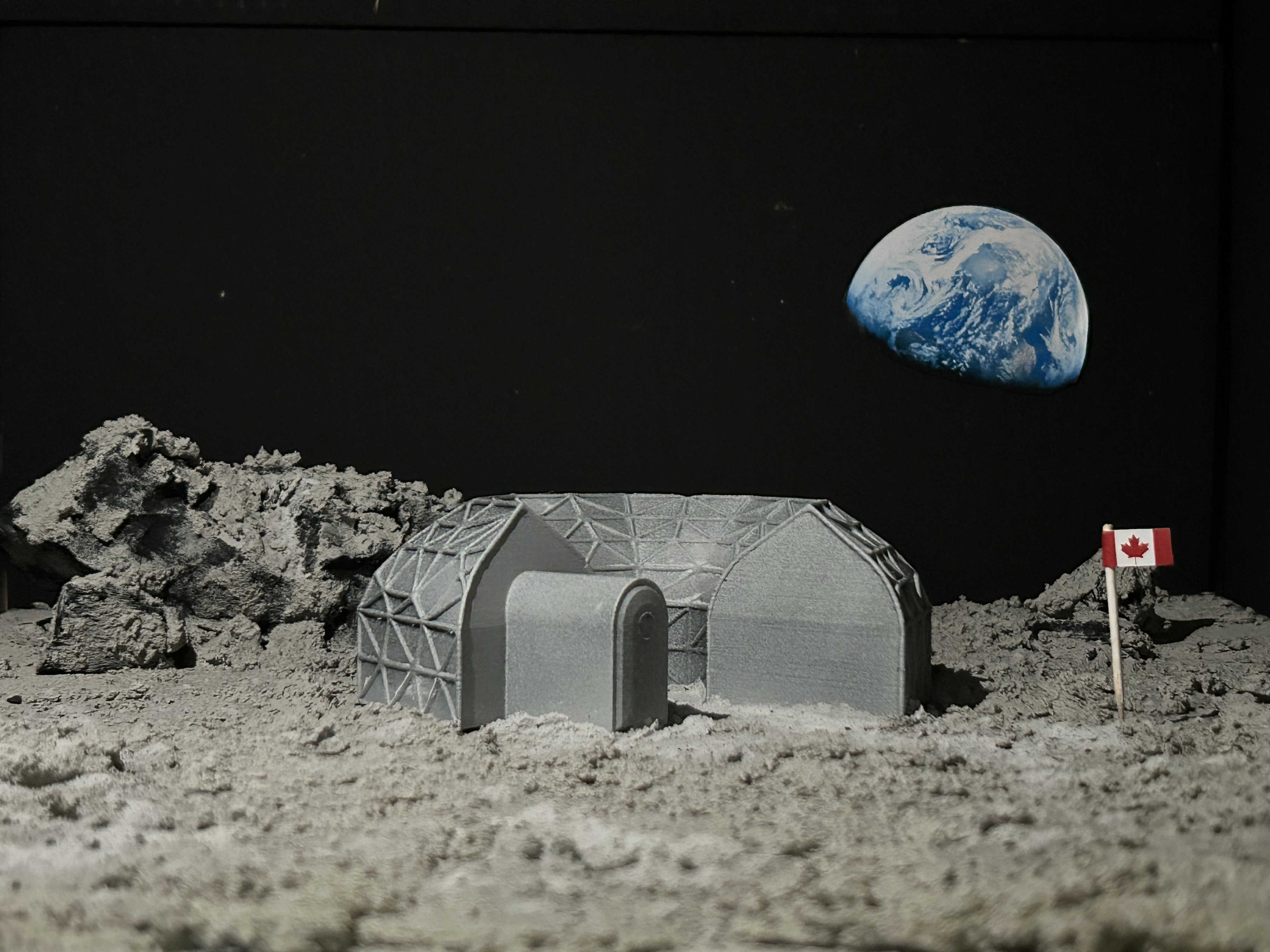
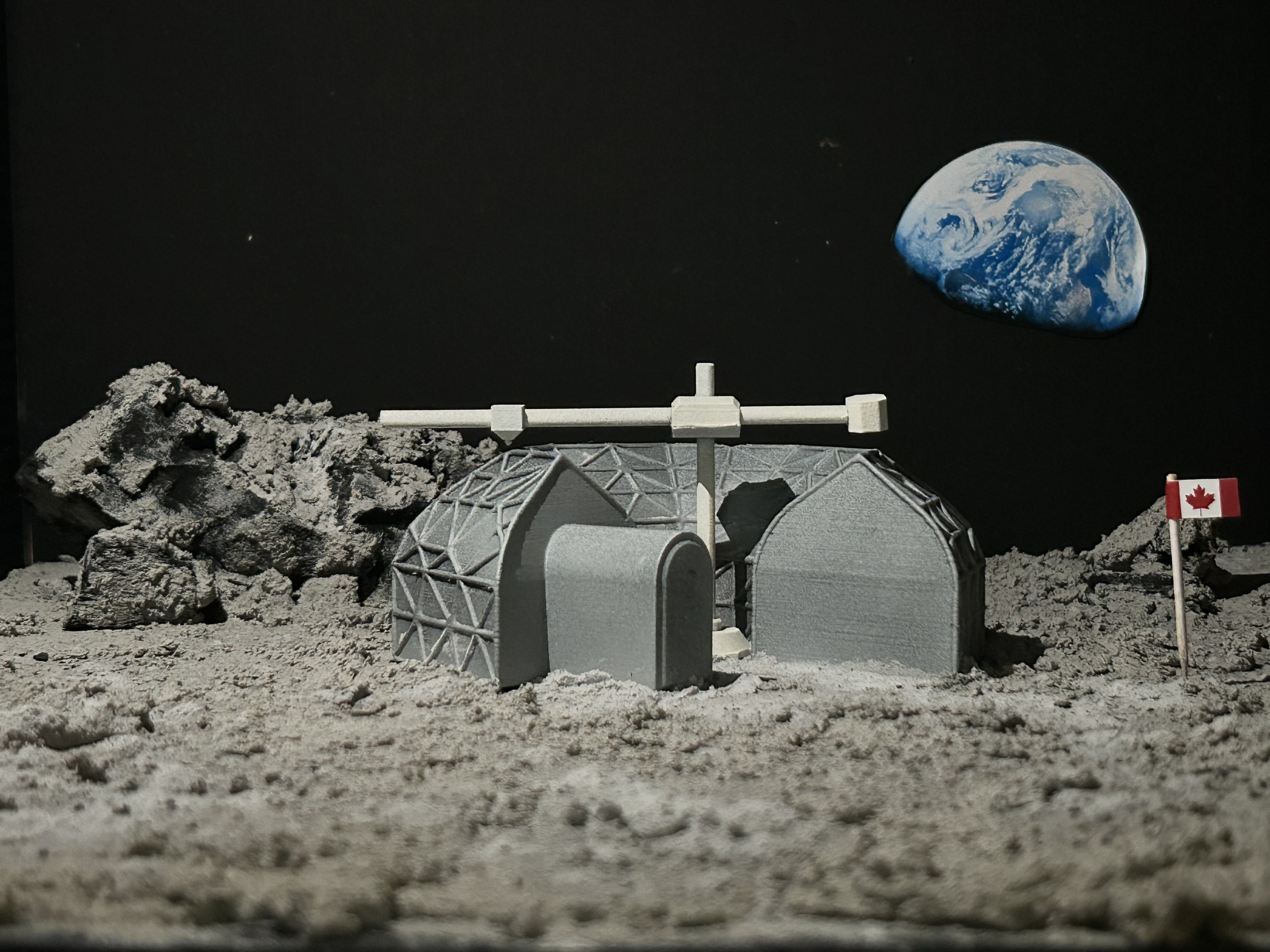
Step 9: After taking shots with and without the printer, I took the model out to cover it completely in the fake charcoal-flour, just like how the actual structure would be covered for insulation. Then I put it back in and took a few more photos.

CONCLUSION
This project has been in the works for over two months and I am very proud of my final product. I poured everything I could into this project to make sure ever detail was purposeful. Looking back I learned a lot throughout the entire project, much of which will be massively beneficial to my engineering aspirations. I learned a lot about Fusion 360’s advanced functions, many of which have given me inspiration for some future projects. I also learned about project management and material science. And I’ve gained a new appreciation for all the engineers at space agencies around the world and all the incredible work they do.
Thank you so much to for creating this competition to foster my ideas, I enjoyed every second of it!
Thank You!
Oliver