Low Cost Plastic Extruder for Filament Production and Recycling Plastic
by tin-foil-hat in Workshop > Tools
49835 Views, 524 Favorites, 0 Comments
Low Cost Plastic Extruder for Filament Production and Recycling Plastic


If you are just interested in the build you can skip to step 4
Too Long Didn't Read:
Less than 10% of all plastic waste is recycled... We can do something about this.
Why not make your own 3D printing filament!! it can cost as little as a dollar per kg or even free!
You can turn failed prints, and most importantly recycle household plastic waste such as bottle caps, and milk bottles into almost anything! With modern multi-colour prints becoming popular, you finally have a use for all those 3D-printed purge towers and 'poops'.
Note: Mains power in Australia is 240V AC, if you live in parts of America you have 120V AC. Double-check your mains power voltage online and anywhere I have said 240V AC, you can consider it as your local mains voltage.
Long Read:
My name is Thomas and I am an Australian student in my last year of Highschool and hope to study engineering next year. This means I'm trying to save every dollar I can to go towards college. I started doing smaller projects for Instructables contests as a way of funding my main projects so am super excited to finally share one of my major projects that I've been working on for the past three years.
Plastic pollution is a huge issue in today's society. There is no place on earth that doesn't have a discarded plastic bottle or single-use plastic bag. I've been trying to tackle this issue at a community level because if recycling machines could be made for low cost and with no custom parts, both makers and developing countries would be able to recycle large amounts of their own household plastic, reducing stress on recycling plants and letting the government focus on large scale prevention and removal of existing pollution.
Most online sources and tutorials that talk about "affordable" plastic extruders easily cost over $1000 once you delve into material costs and electronic parts. Whilst they are still much cheaper than the industrial machines that can range from 10's or even 100's of thousands of dollars, most individuals still don't have $1000 to spend on plastic recycling machines. This is why I set out to make a truly affordable extruder that doesn't sacrifice too much on efficiency or output rate. Not only that, but it can't have any specialised parts or need any advanced machining (just simple welding, 3d printing, or woodwork).
But the question is, what do you do with all this plastic?? Whilst the sky is the limit on what you can do with molten plastic, the true limit for most is again the cost. Aluminium moulds can cost thousands of dollars by themselves, but with the record number of households with 3D printers, I realised that if you could turn plastic waste and failed prints, into usable 3D printing filament, you could eliminate the need for moulds. Not only that but you could save a pretty penny when it comes to the cost of buying filament.
This instructable will be focused on the plastic extruder itself, but I will be writing up another instructable on the machines that automatically wind up the plastic output into filament when I have moments to spare from school exams. If this interests you, make sure you follow me so you're more likely to see its release!
Criteria:
- Inexpensive (Under 300 AUD which is around 200 USD)
- Only requires basic machinery and/or tools (3D printing, basic woodworking tools, and welding steel)
- Efficient (Must be able to recycle at least a kg of plastic per hour at max speed)
- Reliable (Isn't prone to failure due to cheap parts)
- No specialised or custom parts (Only parts that could be found in developing countries or bought online)
- Serviceable and Modular (Parts should be interchangeable, making it easier to incorporate salvaged parts into the design as no tolerances or dimensions are critical. This also makes it easier to replace broken parts)
How much money can you save?
Since this machine recycles plastic waste, any products you make with it essentially cost nothing to produce. The main goal is to produce 3D printing filament from household plastic waste however, an alternative spin on this extruder is the fact you can make your own filament from failed prints mixed with virgin pellets. And you can save a lot of money. Depending on where you buy your pellets you can make a kg of filament for under $5! And if you are making your filament from recycled plastic there are no material costs making it essentially free! (I keep saying 'essentially free' as it does use electricity, but with solar panels becoming more popular, even that cost might be nullified).
What if I'm broke?
Well so am I! Being a high school student I have no money to spare for my projects. Depending on shipping costs and availability of local parts (and depending on how much you can salvage) I estimate it costs just under:
- $300 Australian Dollars
- $200 United States Dollars
- €180 Euros
- £160 Pounds
(Depending on your currency)
Given that is the same cost as about 10 rolls of filament, it quickly covers its own costs in the long run.
What if I can't weld?
Don't worry. Welding isn't as scary as it may first seem. This was the project that I started both my stick and MIG welding journey on. The welds don't need to be beautiful, and remember you're not making a bridge or anything structural, just a frame and a few extra bits and bobs. If you don't want to learn to weld, maybe you know someone who does. Or maybe someone else in your community can help you out.
I hope this project inspires others to help tackle worldly issues in creative ways. I have no engineering degrees and am entirely self-taught so please share any advice or tips you have in the comments below so we can all learn from each other. If you need clarifications or more information about how I did certain steps, you can comment and I will reply the best I can. This instructable may be updated as time goes on with improvements but I'll try to make it as clear as possible where I've updated sections.
Without further ado, let's get building!
Disclaimer
This project uses mains power. This can kill you and is not to be taken lightly. Make sure you are confident with the wiring you are doing. I spoke with an electrition friend of mine the first time I wired up my prototype to double-check everything was correct. Remember I am only a high school student with no degrees in engineering so take everything I say with a pinch of salt and remember there is never any harm in double-checking my instructions. If you spot any mistakes, please leave a comment and I will look into it further and update the Instructable.
Note: Mains power in Australia is 240V AC, if you live in parts of America you have 120V AC. Double-check your mains power voltage online and anywhere I have said 240V AC, you can consider it as your local mains voltage.
Supplies


The supplies and tools needed will vary slightly with how you adapt my design to suit your needs. However below is a comprehensive list of what I used. You should read through the entire Instructable once before you start buying parts so that you can figure out if you already have alternatives to parts or tools (as I elaborate on each part in its respective step). I will also list in brackets where you can salvage the part if applicable, and the price in Australian dollars (around 1.6x the US dollar) - The price is only indicative as currency and availability of parts will change with location (as in Australia we are isolated from most major manufacturers, hence our parts cost significantly more). I'd recommend you look into salvaging parts where possible, it makes the entire process more rewarding and gives character to the machine! All up, both the electronics and mechanical parts cost a total of $278 AUD or $185 USD, which is cheaper than most 3D printers!
(None of the links below are affiliate links, they are just to help you see what I bought)
Electrical Parts (Around $139 AUD ≈ $92 USD)
- 2x PIDs (I used Inkbirds ITC-100VH - and would highly recommend)
- 2x Type-k thermocouples
- 2x SSRs and heatsinks, if they don't come with heatsinks you can repurpose old CPU heatsinks or salvage heat sinks from old electronic devices
- (You can normally buy the PID, thermocouple, SSR and heatsink together; link here) Total: $70
- 2-4 Band heaters that suit your barrel (mine were slightly oversized at 35X45mm 220V 150W and I bought 4 as they often come in packs of two; link here). Try to find heaters that are designed to fit the OD of your barrel pipe as if they are oversized you will need to make a spacer. $18
- Motor speed controller (I talk about finding a motor later, thus don't worry about this until you choose a motor) $20 (link here)
- M3 bolt used for connecting ground/earth wires
- 4x chassis mount fuse holders + fuses to match (I show you how to calculate fuse values later on) $8
- 1x DPST switch (rated for 10A and 250V - coloured red) $4.80
- 1x DPST switch (rated for 15A and 250v - coloured black) / SPST switch (if you have a DC motor) $3.50
- Optional red 240v LED globe $1.70
- Optional green 12v LED $1.70
- A power supply for your motor (I used an old computer ATX PSU - if your motor runs of mains power you don't need to worry about this step)
- 2x old PC fans (or AC fans if you aren't using any DC power - my motor runs on 12V DC so I used that transformer to power the PC fans) + fan blade covers (either wire or 3D printed, normally salvaged fans have wire covers already that can be salvaged too)
- Thick wire (this should be used for all high amperage wiring, such as heaters and the motor - I bought the end of a used roll on clearance. Check your motor current draw as well as the current draw of your heaters and use an online AWG chart to calculate the gage of wire needed) $4
- Thinner wire (thin wire should be used for all low amperage wiring, such as LEDs and PIDs) - You can strip old appliance power cords and reuse the cables
- Additional cables for connecting electrical earth/ground to the frame (ideally with ring connectors that fit over an M3 bolt - these can be salvaged from old appliances and often already come with ring connectors)
- Screw terminals $2
- Chassis-mounted mains socket (only needed if you are powering an external power supply - more on this later)
- An old appliance power cord (make sure it can withstand the required amperage to power the entire machine, I found 10A is fine for my purposes). I cut an extension cord in half to ensure the cable wasn't damaged by the previous user (link here) $3.50
- Optional: An inline switch for your power cord (link here)
- Optional: Additional fork or ring crimps for connecting wires to the terminals on your PIDs and SSRs
- Heatshrink (please don't use electrical tape...) $1.90
Mechanical Parts (Around $139 AUD ≈ $92 USD)
- A wood auger bit, mine was 25x460mm but take note this isn't the flute length (flutes are the spiral section), but rather the total length (link here) $25
- A small section of steel pipe that just fits over the end of the auger bit's drive shaft (this is to prevent kickback which I will talk more about later, you can salvage this from an old bike frame, chair legs, etc - only needs to be around 5cm long)
- A steel pipe for the main barrel, make sure the pipe fits the auger on the inside and is long enough for the entire length of the auger bit's flutes (I used a 25mm ID x 450mm long pipe). I would highly recommend sourcing a pipe with at least one threaded end (I sourced mine from my local hardware store for $10). Additionally, if possible, find a pipe with no 'seam' weld inside. If yours does have a seam (which mine did), you just need to file it out.
- Female to female reducer for the nozzle of your barrel, make sure it screws onto the end of your pipe (mine was 25 to 20mm; link here) $2
- A metal pipe plug that screws in the end of the reducer, serving as the tip of the nozzle (in my case 20mm; link here) $2
- A sheet or circular cutouts of 50 mesh, stainless steel, this is used for the melt filter $4
- Box tube around 40x40mm, this is used for the main frame (I salvaged all mine for free from someone throwing out what appeared to be a cabinet; look out for people removing patios, metal supported tables, or any other structures that contain square or rectangular metal tubing)
- Several screws, both for wood and metal (These were all salvaged from disassembling old electrical devices, but you could buy a pack if you wanted. If you're a woodworker, chance is you have some lying around).
- A flexible coupler that suits your motor shaft and the shaft of the auger bit (some other options are provided later on) ~$15 - 20
- Pillow bearing that suits the shaft of the auger bit (should be a tight fit), mine was a UCFL201 which has an inner diameter of 12mm (link here) $11
- High-temp spray paint (normally sold for BBQs or car engines - I bought mine at a local automotive store) $12
- Standard water-based spray paint (this is just for the remainder of the frame) $8
- Sheet metal (This can be salvaged from old cabinets and file storage units, alternatively you could use an old car bonnet)
- Exhaust wrap + metal zip-ties (this is for insulating the barrel and are often sold together - alternatives are provided later on; link here) $14
- High-temp tape (this is for insulating the hopper, you could also use a small piece of wood or rubber washers; link here) $7
- Assorted bolts for the frame, all are 10mm (M10) and most are 50mm long, however, you will need to adapt this length to suit the material used for the frame and barrel holder + nuts to suit $5
- 4x M5 bolts to hold the hopper in place $4
- 4x M6 bolts and nuts, alongside 1/2" washers (These are used for the feet of the extruder. To find the correct size bolts for your frame, find a washer that just fits inside the box tube used for the legs, then find a nut that just fits inside the washer) $2
- Expanded mesh to cover the barrel, alternatively you can use sheet metal (you can salvage the mesh from an old pedestal fan cover)
- Thick, large, steel mesh to cover the hopper (can be salvaged from old baskets, shoe racks, etc)
- Angle iron (Can be salvaged from construction site offcuts, or demolition sites)
- Small lengths of flat bar to weld to the barrel as mounting brackets for both the hopper and the barrel itself (can again be salvaged from construction site offcuts or you can cut rectangles out of thicker sheet metal that could be scrapped from old machines like woodchippers)
- 2x 6mm steel strips (for welding to the frame as 'fins' that the barrel holder can be bolted to), I salvaged these by cutting rectangles out of a piece of metal once used to support the upright section of a treadmill
- A small length of wooden planks is used for some wooden inserts in the frame (This can be salvaged from old table tops, or from pallets, however avoid MDF)
- Additional planks of wood or ply to build an electronics box (could be salvaged construction ply offcuts from building sites or pallets)
- A short length of dowel (or any long thin piece of wood/metal you have lying around)
- A motor to drive the extruder (more on this later, there are lots of different options and all are salvaged)
- A hose clamp that fits around the body of the motor (only needed if there are no mounting points on the motor and it doesn't have inbuilt cooling) $2
- Thin steel mesh and an air filtering mesh (filtering mesh is optional, this is for the air intake on the electronics box cooling - you can salvage these from old PC cases or just 3D print a cover)
- Muriatic acid or household vinegar to remove galvanisation
- 3D printing filament, I used around 0.6kg of black PLA $15
Tools
- 3D Printer (I have a modified Ender 3 V2)
- Angle grinder (with metal cutoff and grinding disks)
- Welder (any type will do)
- 90° welding magnets, clamps, or another method of welding box tube together at 90°
- Pliers
- An adjustable spanner (or a spanner set)
- A Phillips screwdriver (for smaller screws that would be overtightened with a drill)
- A cordless drill with a Phillips bit (for wood screws) and a range of drill bits (for wood and metal drilling) + a hole saw bit (this isn't strictly needed)
- Optional: Drill press/Corded drill (may be more suited for drilling some of the pilot holes)
- A socket wrench (or socket screwdriver for tightening bolts)
- Soldering iron + Solder (lead-free solder is better for your health)
- Optional: Soldering 'helping hands' and brass wool for cleaning your soldering iron tip
- A lighter or heat gun (if you choose to use heat shrink which I hope you do...)
- Wire cutters/Side cutters
- Wire strippers (I would highly recommend automatic strippers)
- Pencils and a marker
- Wood or metal working clamps
- Wood saw, drop saw, table saw or other method of cutting wooden planks
- Depending on how you build the electronics box, you may also need a laser cutter/CNC router (you can otherwise use simple woodworking tools to make a box, which I'd recommend and talk more about later)
- Depending on how you cut the panel of the electronics box, you may need a coping saw/jigsaw or CNC
- Metal file
- Sandpaper or a wood chisel
- Utility knife / Scissors
Personal Protective Equipment
- Silicone gloves (for handling molten plastic, you can pick up a pair of cheap BBQ ones) ~ $8
- Welding mask, gloves, apron etc.
- Respirator (for welding and melting plastic - although providing you don't burn plastic, and you only melt non-toxic types, you should be safe)
- Eye protection (for pretty much everything but 3D printing, you only get one set of eyes!)
- Ear protection (for when grinding or using power tools)
The Concept

The concept of a plastic extruder is simple but important to understand. All we are doing is pushing small flakes or pellets of unmelted plastic down a heated barrel which heats the plastic to a desired temperature, melting it, and then forcing it out a nozzle in a desired shape. The advantage of an extruder compared to an injection machine is that we can get a continuous flow of plastic. When it comes to the method of moving plastic, we use a screw-shaped profile. Purpose-made extrusion screws taper outwards towards the end of the screw, compressing the plastic which gives a more consistent flow. Additionally, the compression generates heat through friction which greatly assists in melting the plastic. However, purpose-made extrusion screws are extremely expensive (and extremely efficient), so in this build, I use a wood auger drill bit, which does the job and saves my wallet!
Dave Hakkens explains this concept further in his extruder construction video which has been embedded below (The explanation is from 3:20min to 4:10min)
Lately, another 3D-printing filament-making method has more recently become well known. This is called "pultrusion". This method uses strips of PET plastic bottles and softens them by pulling them through a 3D-printing hotend, forming them into a circular shape. This should not be confused with a plastic extruder, as rather than melting the plastic, it is simply folded in on itself, leaving a slightly hollow centre. Whilst the method works, it is slower and is limited to the length of filament one bottle can produce (without then also introducing joins in the filament). Additionally, it only works with PET bottles, which can be recycled in household waste (or be returned to the shops for 10 cents in Australia). CNC Kitchen delves more into this process and his video can be found here.
Pultrusion is an amazing low-cost idea for those who are interested, but to recycle plastic of different shapes and sizes and not be restricted by some of the limitations pultrusion brings with it, I chose to build a plastic extruder.
(Credit to Dr. Harold Giles for the extruder diagram above)
Existing Machines

I am in no way the first person to think of this idea, and some other amazing makers can be found by following the links below. These links are great resources however, most of them are either too expensive for hobbyists, require advanced parts and machines, or are not as efficient as they could be. My design isn't perfect and is a constantly evolving prototype as well, but I have tried to meet the previously mentioned criteria as best as possible. You can find some of the best sources below:
- Precious Plastic (Dave Hakkens + Co)
- Filament Factory (ianmcmill)
- ArtMe3D's Extruder
Other sources include:
- Nezonezo's Extruder
- Werbewunder's Extruder
- Lyman Filament Extruder (Lyman / Mulier)
- Filastruder
Prototyping


The first step in any large project is to prototype. This meant building an extruder out of wood and some metal pipes and brackets. To my surprise, it worked fairly well. The issue came from the fact that as the motor spun, the wood would flex, causing the entire barrel to oscillate and give an inconsistent output. For basic extruding projects, this might be good enough, but since my end goal was 3D filament, I needed a more reliable machine.
Whilst this prototype is cheaper and easier to build, I am not going into depth on how to build it as it was only a prototype and version 2 is a much more powerful machine.
I also took the prototype to a showcase to ask for advice and opinions from the general public and business officials. This helped me to collect data regarding the usability and safety of the machine, but most importantly get people excited about recycling. (In one of the images above you can see a sneak peek at the second stage of this project's prototype, which is the winding mechanism - more on that later).
Useful Diagrams and Files


This step is just dedicated to a place to collate all the drawings, schematics, and files you will need or might want to reference when building this machine. All the drawings above are for reference only, some measurements will not be exact as I modified things as I went to suit the parts I could salvage. Use them as a general template and idea when building your own machine, and to help give you a sense of scale.
The STLs, PDFs, DXFs and Fusion 360 models can be found on printables here: STL Files
I have also made a YouTube playlist of all my small videos that are embedded throughout this Instructable: Playlist
Finding a Motor


A motor and gearbox can be one of the most costly elements of this build, but it doesn't have to be. What if I told you I got all four of the motors above for free (or close to it). For an extruder, we need a slow-speed, high-torque motor. Most instructions gloss over finding a suitable motor simply because of how hard it is. You can go and spend a few hundred dollars for a motor and gearbox but that ultimately defeats the purpose of an affordable extruder.
Some people (including myself when prototyping) use a windscreen wiper motor. These motors are super cheap if you can buy them from someone who is scrapping their car (I got mine for $10). They run off 12V DC. They use a worm drive gearbox to turn a slow and powerful output shaft. The issue is, they are simply too small. You could possibly use 2 or 3 of them all turning the same gear (like a modified planetary gearbox design) but I just chose to look for a larger motor.

The next two motors are from a treadmill. The first of which, is the inline motor. This is the motor that raises and lowers the track height so has a super high torque output and low speed. It runs off 240V AC (or 120V AC if you have an American-made one). The issue with this motor is it isn't designed for continuous load. Since you only periodically include or decline a treadmill, this motor hasn't been designed to run continuously for long periods. I was still planning on using this motor with a large amount of cooling until I changed to a wheelchair motor, so this is still a potentially viable solution.

The second motor from the treadmill is the main one that drives the belt. This motor is huge (and heavy). Surprisingly it runs on a DC voltage (of around 110 - 90V). Reusing the motor driver that came with the treadmill proved to be more difficult than expected however, older models likely have less pesky safety features you need to overcome. With my limited knowledge of DC motors alongside some tests, I found that even when running the motor on its slowest setting (lowest voltage) I was unable to stop the shaft spinning with my hand (a very technical and safe test...), but it did draw a higher current. This makes sense as back EMF is proportional to the velocity of the internal coil, and hence at lower speeds, it should draw a higher current to output the same torque. I don't know enough to come up with a definitive answer, but I think you could run a treadmill motor at its slowest speed and still get enough torque to turn the extruder auger. Someone with an engineering background could probably help answer this question (leave a comment)!
If you wanted to slow down the output of the treadmill motor (or any fast motor) you could use a series of pullies, sprockets or gears. I mention this more later on when discussing couplers and how to mount your motor.

I was lucky enough to be given some old electric wheelchair motors. These are perfect. They have slow speed, and high torque, are designed for continuous load, and run on 12V DC! If you can get your hands on these second-hand, I would highly recommend looking into it. However, I know not everyone will be as lucky as I was. You will see that throughout this design, for the first half, I plan to use the treadmill incline motor before I was given the wheelchair motors. All the other motors mentioned are still viable options, but you'll just need to look into gearing them down/up with pullies etc.

I have also heard of some people using large stepper motors such as Nema 23's. I am not sure they have the torque output for this size of an extruder, but if you downsize the barrel they might work.
Having a motor with controllable speed is also an important consideration. You can see two motors in the video below spinning at max speed, notice how the incline motor spins faster than the windscreen wiper motor, but since it internally has a higher gear ratio, it can also spin slower (I didn't have an AC speed controller available at the time so the video doesn't show this).
The Barrel


Arguably the most important element of the extruder is the barrel. This is where the heating of the plastic takes place and where the auger bit spins inside. After buying your auger (mine was 25mm in diameter), make sure it fits inside your chosen pipe with only a little play. If you have a huge die-tapping kit you could buy a pipe without threaded ends, but I found it was much easier to buy a galvanised water pipe as it already came with a threaded end for our nozzle. If you buy a welded pipe, you will have a seam on the inside you need to remove. It's easiest to cut the pipe to length first and then to file down the seam, this way you have less to file down. You can also cut off the pointed tip of the auger bit. This isn't necessary, but it can help to maximise the usable area of the barrel.


We also need to cut out an intake slot for the hopper. By placing 2 blocks of the same height on either side of the barrel you can then mark out the desired area to cut out (credit to Dave Hakkens for thinking of this idea!).

We want to cut the slot a few centimetres from the end without the thread. Make the cut halfway across the pipe so that we can fit the largest plastic chips possible (as seen in Dave's photo above). Since angle grinders have circular cutting disks, you'll need to slightly undercut in order to avoid overcutting the corners. A flathead screwdriver can then be hammered into the scores and used to pry off the bit of metal. Finally, use a file to smooth out the corners of the intake slot.

When determining the length of the barrel, slide the auger bit inside so that the end is just shy of the end of the pipe. Then cut the pipe so that almost all of the drive shaft of the auger sticks out one end. Then to determine how far away the start of the hopper intake should be from the end without threads, you should try and aim for the start of the auger flutes, to line up with the start of the hopper intake (this way you maximise the length of usable barrel). My hopper intake is 90mm long. This is hard to explain so hopefully the drawing below helps to make more sense. If you find the auger bit is still too far inside the barrel, you need to cut the barrel shorter so that you have enough of the hex end sticking out to slide through a bearing and for a coupler to attach too.

The Hopper


.jpg)


To make the hopper we first need to print out the templates I made in Fusion 360. You will need two copies of the side with a flat bottom and two copies of the side with a circular cutout on the bottom (ignore the small trapezium-shaped part for the time being). Since each segment of the hopper was slightly too large for an A4 printer, you will need to use a ruler to connect the missing lines. Using an angle grinder, you can cut out all 4 of these parts from some scrap sheet metal (mine was 1mm thick). You will also need to drill the two 5mm holes on each of the sides with a flat bottom. To cut out the circular segment on the front and back plates you have a few options:
- Use a large metal hole saw
- Drill a series of small holes in the semi-circular shape and then use a round file to smooth out the curve
- Cut a series of lines with an angle grinder and then use a round file to smooth out the curve
Once you have all your sides cut out, you also need to cut 2 smaller trapezium-shaped parts from thicker (3mm) steel (I managed to fit both on an old flat bar offcut). These will be welded onto the barrel later as a way of bolting on the hopper. Whilst the paper template also has the holes marked out, I would highly recommend using the holes you have already drilled in the sides of the hopper as a guide, as all that matters is that they line up.
By laying out each side of the hopper on a flat surface, you can tape the sides together. This makes folding it into its final shape much easier. Then apply some more tape to the outside of the hopper to help hold its shape better when welding.


Now all that's left is to tack weld the sides of the hopper together in a few places. You don't need to weld the entire edge but you can if you feel the need to. Then clean up your welds and spray paint the whole thing!


The Barrel Holder


Next, we need to build the barrel holder. The barrel holder is the part that connects the barrel to the main frame. To make parts easier to service and replace, the barrel is not welded to the holder but rather is bolted on. To achieve this, we need 2 pieces of flat bar to be welded onto the outside of the barrel. You could use just one piece, but since the scrap rectangular tube I was using was 20mm across (so 40mm total when using 2), I needed two pieces to fit properly. It is hard to explain exactly what I mean, so hopefully the images and drawing below help to show what I mean. You can see how with only 1 piece of metal flat bar on either side of the barrel, the total width is equal to the width of the 2 rectangular beams (this means we have nowhere to bolt into). Hence, I needed 2 pieces of metal to give me somewhere to put bolts through.


The barrel holder will also have a bearing mounted on the back. The bearing serves two purposes. The most obvious is to help align the auger bit to the centre of the barrel. However, every action has an equal and opposite reaction (thanks Newton!), this means as we are pushing plastic out the end of the barrel, we are getting a 'kickback' force that pushes against the motor shaft. The motor isn't designed to have force applied down the shaft, so the bearing will also prevent kickback. We will need to drill 2 holes in the top of the angle iron for the bearing to mount to.
To hold the bearing in place, we just need to use 3 sections of angle iron (mine was scrap and hence you can see it is currently covered in cement). In some of the photos above you will see I only have one rectangular beam with the two upright L-shaped angles facing inwards, this was the way I originally designed it, but I since found a better way to do it.
- Using two rectangular beams on the inside rather than just one, gives a larger 'footprint' making it easier to mount to the frame, and it makes the holder stronger.
- Due to the increased width of the 2 rectangular beams, you will need to rotate the L-shaped angles to face outwards otherwise it simply won't fit.
- The angled box tube that is at the front of the holder was designed as a mounting point which was later changed to be 2 lengths of box tube as the thin metal was too hard to weld securely and was later removed altogether and replaced with 2 large bolts (so just ignore it).
Acid Bath


Since the barrel will be heated up for long periods of time it is important to remove the galvanised coating to prevent toxic fumes from burning off. There are 2 ways of doing this:
- Use household vinegar. This is probably the easiest method. Simply fill up a large tub with white cleaning vinegar and leave it for a week to dissolve all the zink. It does however leave it smelling really metallic which may not bother you, but I hated it.
- Using muriatic acid (aka hydrochloric acid/pool acid). This is the method I used. I added one part of acid to four parts of water (Always add acid to water, not water to acid). This stuff is highly corrosive and will strip the zink off in minutes. You can lower your parts into the acid by wrapping some metal wire around them. Make sure you do this in a well-ventilated area and take property safety precautions when dealing with a strong acid (wear gloves, eye protection, old clothes, have a water source nearby and a base such as bicarbonate dissolved in water). When you remove the parts from the acid, you will want to dip them into a basic solution (such as bicarbonate dissolved in water) to neutralise the acid.
The metal should turn a dark grey and lose its metallic shine once the zink coating has been removed.

The top is bare steel. The bottom is still zink-coated.
Make sure you are using a plastic or glass container otherwise the acid may eat through the container itself! It is also recommended against welding galvanised metal, so we might as well remove the galvanised coating of all the parts for the barrel holder whilst we're at it. You should always wear a welding respirator that filters out any harmful fumes and particulates when you weld regardless of whether the parts are galvanised or not.
Welding It Togeather


Now that the parts are no longer galvanised we can weld everything together. You will want to clamp all the individual pieces together as best as possible to avoid any warping. Weld the 3 L-shaped angle iron pieces together to the 2 rectangular beams as shown below. Before you weld them together, check your bearing fits. I needed to file a small divot out of the bottom L to accommodate the shape of the bearing. You can ignore the small square tubing that was shown in some of the images (as previously mentioned) as that was the first iteration of the design and was later removed.


I don't have any photos showing me welding the four 3mm steel pieces (two on each side) to the barrel. However, based on the drawing from the previous steps, it should be clear where to attach them. You can see this somewhat in the image below.

You also need to weld the brackets onto the side of the barrel where the hopper attaches to. It is easiest to bolt the small flanges onto the hopper and then tack weld them in place, before removing the hopper and finishing the weld. This way you can be sure that the hopper will still fit. Thanks again to Dave Hakkings for this tip!

The Nozzel + Melt Filter


Since we have a threaded end on our barrel, we can just use standard pipe fittings. In my prototype, I used a pipe cap which I drilled a hole in but I ran into an issue where the plastic would 'remember' the spinning motion of the auger bit and spin as it came out the nozzle. To prevent this, we need to force the plastic through a longer nozzle. I used a reducing pipe fitting and a metal plug (in which I drilled a 1.5mm hole). This can just be screwed onto the end of the extruder barrel.
Since this extruder is multipurpose, I didn't want to just have a nozzle that makes 3D printing filament. For example, if you wanted to extrude beams you could screw the mould into the reducing pipe fitting in place of the metal plug. This also means you can exchange the size of the hole at the end of the extruder by using different plugs.
I would like to test drilling and tapping a larger hole into a plug, and then screwing in a 3D printing nozzle that is drilled out to 1.7mm as this may give a more consistent output (and closer to the ideal 1.75mm diameter filament). In a future Instructables post, I will show how to turn the output of this extruder into consistent 3D filament using winders, and in that Instructable, I will also explore the effect of different nozzles. So stay tuned!

When I was exploring existing solutions and industrial machines, I came across 'melt filters'. These are essentially small sections of stainless steel mesh that are inserted into the end of the nozzle to capture any contaminants. These can then be removed and cleaned/replaced over time. A maker by the name of ArtMe3D designed some 3D parts that allow you to form the mesh into a point that can then be inserted into the tip of the nozzle. A link to his design can be found here. Since our nozzle is so much larger than the one in ArtMe3D's design, you only need to follow the first few steps until the mesh looks like the one circled in red below. However, after the first few initial tests of running plastic through the extruder, I found the mesh was deformed into the shape of the inside of the nozzle, which makes me think shaping the mesh is an unnecessary step. You can experiment around with it and leave any interesting findings in the comments for others to learn from.


Do take note that the mesh filter will add additional strain on your motor, as it is forced to push plastic through the mesh. It does improve how clean the output is, preventing clogs in your 3D printer nozzle (if you are making 3D printing filament), but if you are planning to use this machine to make plastic beams, inject into moulds, or anything along those lines, you will not need a melt filter, and you will get a higher output if you don't use one.
Band Heaters + Hopper Insulation


Now that we have all the parts for the heating chamber it is time to add the heaters. You could add these later during the final assembly if you want, but I chose to add them now. Ideally, you want at least 2 heaters. You want one heater for the nozzle which should be around 5 to 10 degrees higher, and then another 1 to 3 heaters along the barrel (depending on how long it is). Make sure that there is enough space between the mounting point of the hopper and the closest heating element, as we don't want plastic melting and sticking in the hopper. To further keep the hopper cool, I added 5 layers of heat-resistant tape over the mounting brackets. During later tests, I found the hopper remained cool so I would argue this worked well.

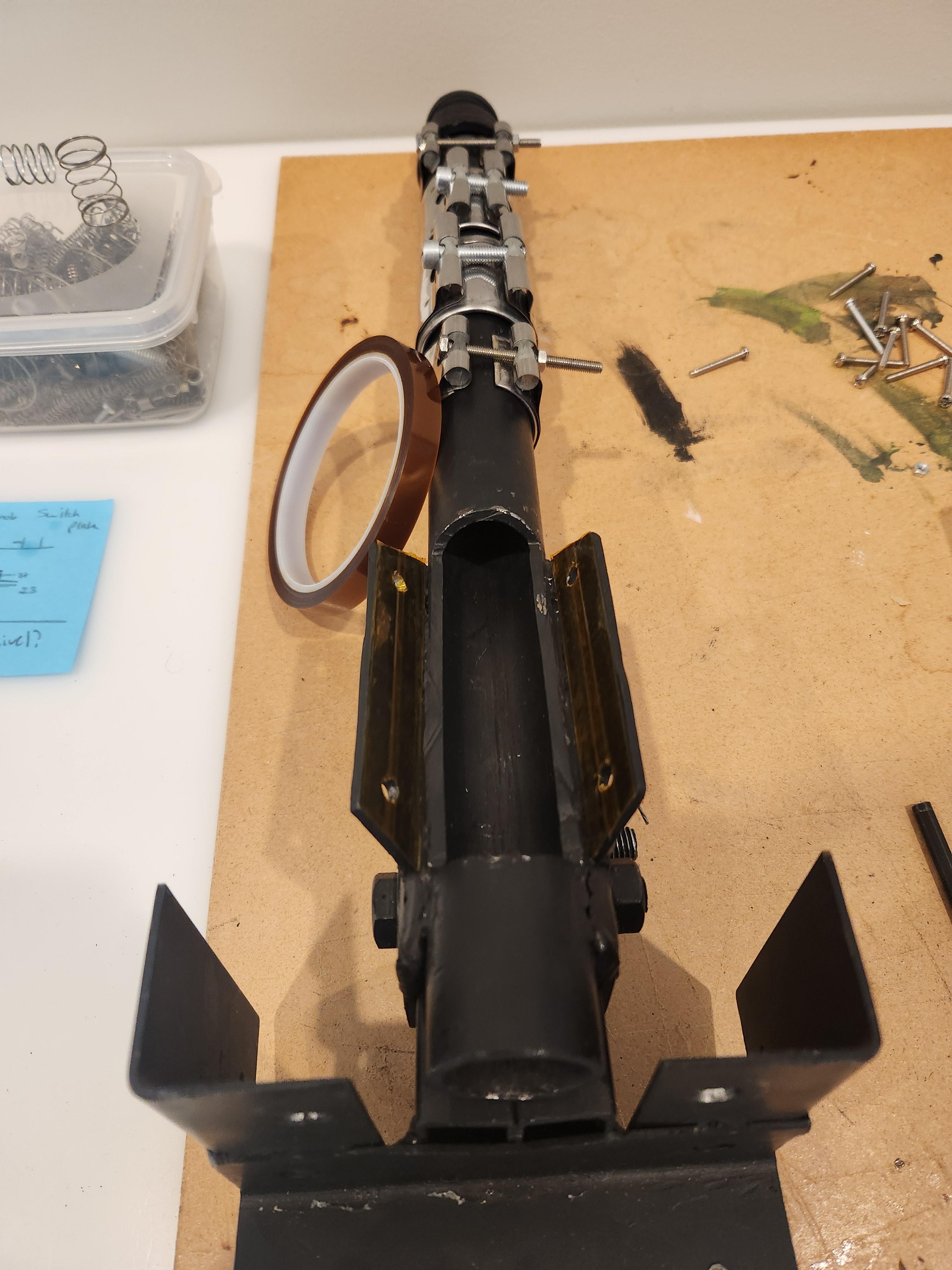
Since there were around 2 years between the time I bought the first 2 heaters (for the prototype) and the second two (for a total of 4 heaters for version 2) I had to buy a different style of band heaters. Unfortunately, the second style was slightly too large for my barrel. This meant I needed to bend some really thin metal into a cylindrical spacer, which I then painted with high-temperature paint as can be seen below (on the left). This spacer would slide over the barrel and then the slightly oversized heater could slide over the spacer. For a barrel the length of mine, you would only need a total of 3 heaters (1 on the nozzle and 2 on the barrel) but since they came in packs of two I just used all four. After you slide on all your heaters you can screw on your nozzle! Leave the middle heater and the one on the nozzle slightly lose, as we will use them later to help hold on the thermocouples.


The Electronics Box


This step has been broken down into three sub-steps to make it more manageable. The first is the physical box/housing, and the second and third is the electrical wiring. All the sub-steps should be done simultaneously (as some wiring must feed through holes in the box, and some parts of the box must be built around wires). There is no need to be scared when you see my mess of wires! It isn't as hard as you may think, I have uploaded two new drawings that are the "Ideal" circuit diagrams, which help to break it down even further. I also attached the wiring diagram I used, but it is specific to my parts and specifications and hence won't be of much use other than a reference. Remember, mains voltage can kill you, seek professional help if you aren't confident with what you are doing.
The Box
Ultimately, the box is just a housing that contains all the electronics and provides a control panel for you to monitor the extruder. I chose to laser cut the box out of 3mm ply (as I have access to a laser cutter at my school) however, you could also CNC cut the same DXF file attached at the end of this step, proving you 'dog-bone' the corners so that the fingerjoints still fit together.
Alternatively, if you don't own a laser cutter or CNC router, you could simply make this box out of planks of wood or sheets of thicker ply. Pallet wood, old bed slats or construction ply offcuts would all work very well. If you have a CNC but like the sound of building a more sturdy electronics box, you could then CNC route the front panel and I have an Instructable that shows you how to do that, linked here.
If woodwork isn't for you, you could weld a metal electronics box but make sure you have electrically grounded the outer casing and that you don't have any short-circuits from metal objects touching against the casing.
The below image is just for a panel layout reference, it is from a much later step so don't worry about any of the other parts!

The dimensions of the box will vary with the size of your components and the layout of your control panel, but you can find all my files and templates attached at the end of this step for reference. I would recommend not gluing your box together, this way you can service parts as needed. In my case, since I used 3mm ply, I wasn't convinced that it would hold up the weight of the electronics box without additional support brackets, so I designed and 3D printed some using Fusion 360 (note the L-shaped bracket was designed by 3D_Workspace on printables). The benefit of this was that I could unscrew any panel if I needed to service the components. At the bare minimum, make sure the top and front panels can be removed for servicing. A 3mm top panel wasn't strong enough to hold up my electronics box, so as you can see below, I had to laser cut a thicker spacer out of 6mm ply which I screwed on from the inside (this also helped my electronics box sit flush with the underside of the final frame as 3mm ply wasn't thick enough to countersink my screws). If you can't tell by now, making your electronics box out of 3mm ply comes with challenges :) Consider making the box out of a thicker material and then making the front panel out of sheet metal/thin ply (as most switches/buttons are made to mount to a thin panel - however this can be overcome with a CNC as shown here).


You can see one of my corner brackets has a small cutout (Left image), this was because the layout I chose for my electronics panel was too small, and resulted in the bottom PID needing additional clearance from the bottom-left panel mounting bracket.
At this point, you should be able to attach all your electronic components to your box. Fasten all the switches, fuse holders, and PIDs to the front panel, and then mount the SSRs to their heatsinks and then screw the heatsinks into the base. You can see in the images below that I only had one SSR heatsink (the black one), so repurposed an old CPU heatsink (the silver one). You can also see how I have screwed in the additional 3D-printed support brackets in the right-hand image.


At this point I thought I was going to use a 240V AC motor, so had mounted an additional AC to DC converter inside the electronics box from an old appliance. I simply zip-tied it in place (soldering to AC power outlet prongs doesn't work, I would highly recommend using the end of an old extension cord and physically plugging in the adaptor as can be seen above - you will need the other end of a power cord as the main power supply anyways). You shouldn't need 12V at all, but since I was recycling the PID I used from my prototype, I had two different models of PIDs, one 12V DC and one 240V AC. If you do need 12V for some reason, I would recommend simply using an externally mounted PSU, which I talk more about later.
Since this machine will be running for extended periods of time, and given the electronics box is made of wood, I chose to mount an old PC fan to keep everything nice and cool. I used a hole saw to cut a hole in the side of the electronics box that was next to the SSR heatsinks. I then simply screwed the fan into the side panel. It is up to you how you orientate the fan (blowing air inwards or sucking air out), but I chose to have the fan sucking air out of the electronics box so that it doesn't pull dust into the electronics. This meant I also needed to cut a slot on the opposite side of the electronics box as an air intake. To prevent dust from being pulled in the air intake, I used a filter and thin mesh that I had salvaged from an old PC some time ago. I then used Fusion 360 to design a cover for both the fan and the air intake. You may need to glue the air intake cover in place if it doesn't fit the size of your hole. I had a wire mesh fan cover lying around and thought it looked cool so ended up using that instead of my 3D-printed cover. I forgot to take photos of me doing this process, but I have included some photos below from the final extruder.


We also need to cut some outlets for the thermocouples, heaters, and motor cables. I designed a few different-sized slot covers that I cut holes for, and then inserted into the side of the electronics box. You need to decide how you intend to layout your extruder, if you plan to mount your electronics box to the right-hand side like I have, make sure you cut the cable slots into the left side of the electronics box (as they will face inwards). This will hopefully make more sense if you see a photo from a later step where the external wiring has been done:


Finally, we need to add a hole in the back for a power cable and a grounding bolt. The grounding bolt is just an electrically grounded piece of metal we can then bolt additional wires too, so that we can ground the remainder of the frame at a later stage (for safety reasons). For the bolt, I just used a standard M3 Hex. I designed 3D-printed plugs that could be press-fit into the electronics box. In the bottom image below, you can see I have also mounted an additional mains socket, I talk about this later and you only need it for an externally mounted power supply (so don't worry about it for the time being!).


And there you go! You should have a lovely-looking electronics box! Make sure you read the next substep about how to wire the electronics box before you build the physical box, as some steps need to be done simultaneously!
The Wiring (Heaters)
Before you start wiring your PIDs, check what voltage they are rated for. I unfortunately bought mine 2 years apart and thus had one rated for 12-24v DC and one rated for 110-240v. If you have a lower DC voltage variety, you cannot wire it directly into the mains, you will need to add an additional transformer (such as from an old power supply) to step down the voltage. I recommend buying two mains-powered PIDs as this reduces the need for extra components. If your motor runs on a DC voltage, you will need an external power supply anyway (more on this in a minute) so if you can only find low-voltage PIDs you may be able to power them from the same power supply (using a buck/boost converter if the voltage is too high/low respectively).
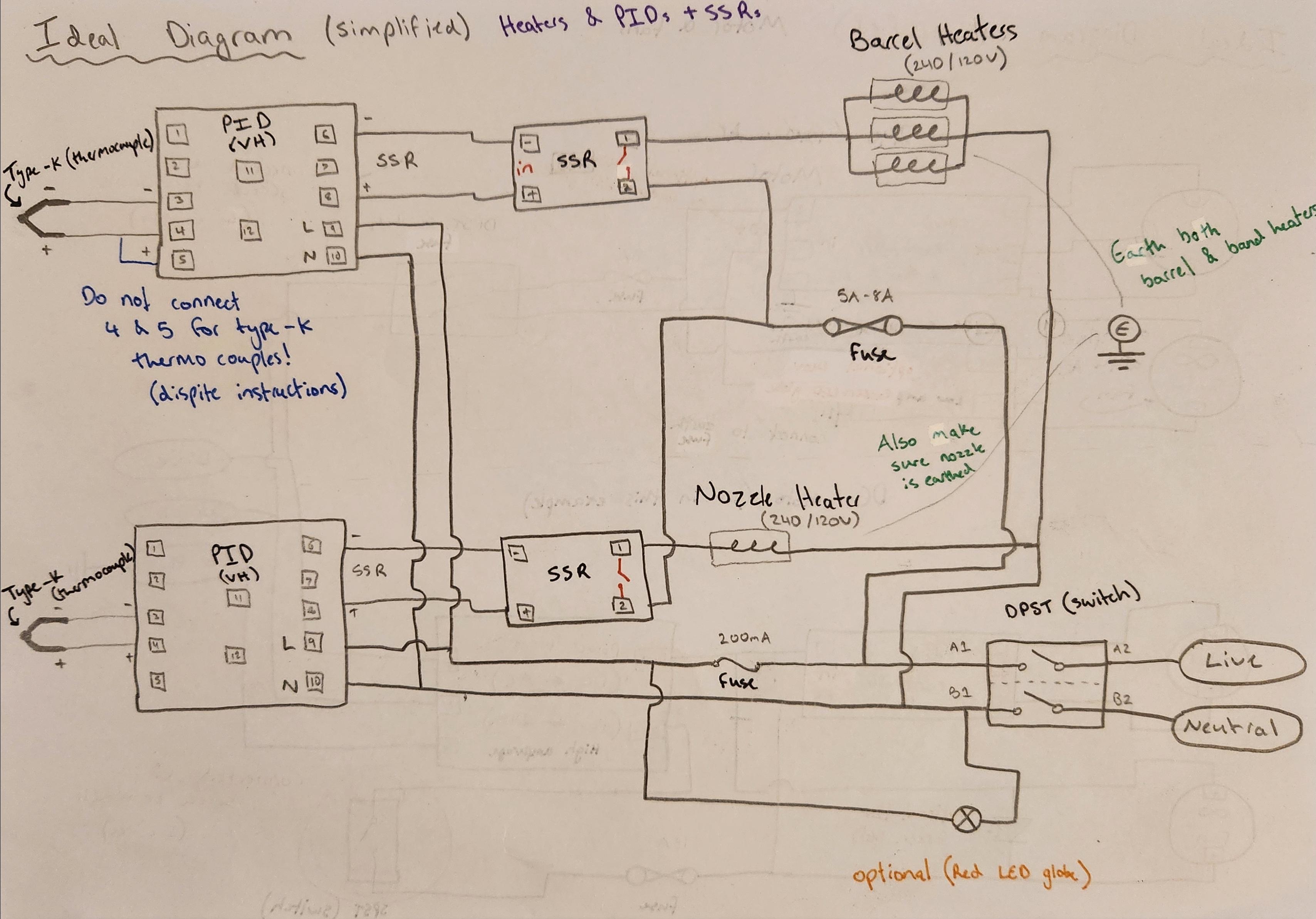
Assuming you are also using an ITC-100VH Inkbird PID you should wire it as shown above. If you are using a different model, the only thing you might need to adapt is what number terminal you connect each wire to. Make sure the gauge (AWG) of the cable you use is rated high enough for the current drawn when wiring the heaters to the SSRs (the current is calculated when we choose a fuse in part 7 below).
- Connect the thermocouple (assuming you are using a type-K) to terminals 3 and 4, where 3 is negative (blue) and 4 is positive (red).
- Make sure you leave terminal 5 unconnected EVEN if your instruction manual tells you to connect it to pin 4 (if you are using a type-k thermocouple). Connecting them will give you random readings. It simply does not work. (See blue wire and writing in the image above)
- Connect terminals 6 and 8 to the input terminals on the SSR. Connect terminal 6 on the PID to the negative input terminal on the SSR and terminal 8 to the positive input on the SSR.
- Connect a DPST heavy-duty switch (Double pole - meaning two isolated switching poles, and Single throw - meaning only 2 positions, on or off) in line with the live and neutral wires from a power cord (this will serve as the main power cord of the machine).
- Do not connect ground/earth to a switch, we want earth to be flowing to the machine constantly in case of electrical failure. Make sure to check the wire colour conventions of mains voltage before wiring anything. You should seek help if this is your first time wiring mains voltage.
- Connect the corresponding live output terminal of the switch to the terminal of a fuse holder that contains a fuse rated high enough for the mains power draw of all the heaters, remember to slightly overestimate this value. Since we are connecting most of the heaters in parallel, we want to simply add the current draw of each one (it is slightly more complex than this due to the way the 3-barrel heaters are wired, but for the sake of simplicity just treat them all as individual parallel circuits). I'm using a 5A fuse.
- If your heaters don't come with a current draw value, you can use the two following equations to help you calculate it. Where I is current (in amps), V is voltage (in volts), P is power (in watts) and R is resistance (in ohms Ω). I = P/V = V/R. If you have a rating of milliamps (mA) divide it by 1000 to get the value in Amps, and if you have a value in kiloohms multiply it by 1000 to get it in ohms.
- Connect the other terminal of the fuse holder (such that the electricity must flow through the fuse) to one of the output/switching terminals on each SSR.
- Connect the last terminal of each SSR (it should be the other output/switching terminal) to an individual cable and leave this unconnected (but cover the end for safety) - One will be connected to the barrel heaters, and the other to the nozzle heater (this is done much later).
- You also want to leave 2 unconnected neutral cables (again, make sure you cover the end of the cable with electrical tape or heat shrink) as these will also be connected to the heaters later on.
- Finally, provide power to the PIDs by wiring another inline fuse (rated much lower than the previous one ~200mA - Calculate this value by adding the current draw of both PIDs and optionally an LED and/or fan). Connecting one side of a fuse holder to the live output on the main power switch, and the other side to terminal 9 on both PIDs. Then directly connect the neutral output of the main power switch to terminal 10 on both PIDs.
- Optionally, you can add a red LED globe (rated for mains voltage) as shown in the image. It serves not only as an indicator that there is power (and the fuse isn't blown) but also makes the whole thing look cooler!
- Also optionally, you can add a cooling fan. These are normally 12/24V DC, so you may need a low-power transformer to step down the voltage and convert it from AC to DC. Alternatively, you could buy an AC fan (a quick Google search tells me these are relatively inexpensive), in which case you can wire this the same way the LED is wired (as shown above).
Nice! Now you are almost done with the electronics box! Arguably one of the most important parts of the machine!
If you want to test if your wiring is correct (which I would recommend), make sure to disconnect the 4 cables that have been left unconnected for the heaters, this way you won't accidentally be shocked by them, and they won't touch and potentially short circuit. Fingers crossed, when you flip the switch, the fan turns on, the lights are shining and the PIDs come to life.
The Wiring... Again! (Motor)
The image below shows two different wiring diagrams. The top is for an AC/Mains powered motor. The bottom is for a DC motor (in my case, 12v).

The majority of this wiring is done in later steps (building the speed controller and then the final wiring). This is because some parts (e.g. the motor) need to be mounted in place before wiring. Fortunately, I designed this extruder to be as modular as possible. This way, the core electronics box can be used for any motor, and the speed controller can be swapped out depending on what motor you are using. All we need to worry about at this stage is the switch, LED and fuse (as they are mounted to the electronics box panel). Just push/screw them into their respective holes in the control panel and leave unconnected wires connected to each terminal to make life easier later on. If you want, you could mount the switch, LED and fuse to the speed controller housing (which we will build shortly), in which case you can ignore all of this and move on to the next step.
If you want to make your life even easier when you come to do the final wiring, you can mount a screw terminal block (on the same side of the electronics box where the heater cables come out) and screw each wire into a terminal. That is what the largest slot cover (rectangular) is designed for.
Hooray! Wiring done. Well... for now :)
Modifying a Wheelchair Motor


If you are also using a wheelchair motor, you will need to remove the brake. The images above show the steps of removing the rear housing and unscrewing the electromagnet. This instructable by randofo goes into depth on how to do it. If you're reading this, thanks!
Depending on the design of your motor, you may now be left with an exposed rear shaft. I didn't want to risk the shaft getting caught on cables, so I designed a motor cap in Fusion 360 which I could screw onto the back by repurposing the holes used for the brake.
If all goes well, you should be able to power your motor and watch it spin freely! You can see a video of me doing that below.
Modifying an Old PSU


This step is only relevant to those using a DC motor. For those running an AC motor, you can skip this entire step and just use the 240v output (from the black switch) as shown in the wiring diagram (this is the screw terminal block on the bottom left-hand side of the electronics box). I had planned to run a 240v AC motor directly from the main electronics box, but after switching from the treadmill incline motor to the wheelchair motor, I now needed to provide a high amperage DC 12v supply. I had a few old broken power supply units lying around, so decided to fix one of them and use it to power my motor. I wrote up a short Instructable on this if you also need to fix an ATX PSU.
Be careful when opening a PSU as they have high voltage capacitors that can hold their charge. If you don't feel comfortable opening a PSU you can just by a 240/120V AC to 12V DC converted with the required output amperage for your motor.
To modify the power supply unit (PSU) to run our wheelchair motor, we need to take all the 12V (yellow) wires, and all the negative (black) wires, and solder them into 2 single wires. This allows all the individual currents to combine and provide a higher output current on a single wire. Since the current will be higher, we want to use a thicker output wire to reduce resistance, and hence reduce the chance of the wire getting hot and melting.


We also don't want to have to plug in the power supply separately. I didn't have the cord required to power the PSU by the inbuilt socket, so I just ran another cord through the back and soldered it to the terminals of the plug. If you don't know what you are doing, just buy a cable and use the inbuilt socket on the outside, it is much safer. If you do solder your own cable through the back, remember to also connect the ground wire (so don't use a cable that only has live and neutral wires), and make sure you 3D print a cover for the plug as when powered, those pins will have 240V AC running through them, which will shock you if touched.


To prevent the cables from being pulled on and hence snapping the internal connections, I designed and 3D printed a cable clip in Fusion 360 which clamps down on the cables and is larger than the output hole, so prevents the cables from being pulled out. I couldn't seem to get the tolerances correct, so ended up wedging a third unconnected cable in there as well, but you could just scale it to suit your cables. Additionally, we don't need any of the other cables so they can all be cut off, or tucked away inside (I didn't cut mine in case I wanted to use the PSU for a different project in the future).


If your motor requires a different voltage, you might need to buy a power supply accordingly, but so long as it has an input of 240V AC (or 120V AC in the USA) the steps should be the same. Regardless of how you power your motor (unless you are using 240V AC directly), you will need a way of providing power to the PSU. You could leave the cable separate and just use an extension board, but I didn't like that idea. Instead, I used a salvaged chassis-mounted mains power socket from a solar water heater (or you can buy the socket for around $5 new) and fastened it to the back of the electronics box. Since my socket was salvaged I hadn't considered the fact it was designed to mount to a thicker pannel (as my electronics box is made of 3mm ply), so I needed to design a simple spacer ring in Fusion 360 to 3D print. This means the PSU can simply be plugged into the back of the electronics box.


There are two options for wiring up the socket:
- Always On. If you wire the main power cable directly to the socket, such that when the machine is plugged in, the socket has power, it means the PSU will always be running given the machine is running. This is the option I opted for as it means the power supply undergoes fewer power cycles.
- Switching. If you wire the output AC voltage from the switch that controls the motor, (from either the screw terminal or the switch) the PSU will turn on only when the motor turns on. This means the PSU will undergo more power cycles, but will run for less time overall.
Remember to directly wire ground into the back of the socket (so that it is always grounded) regardless of what method you choose.
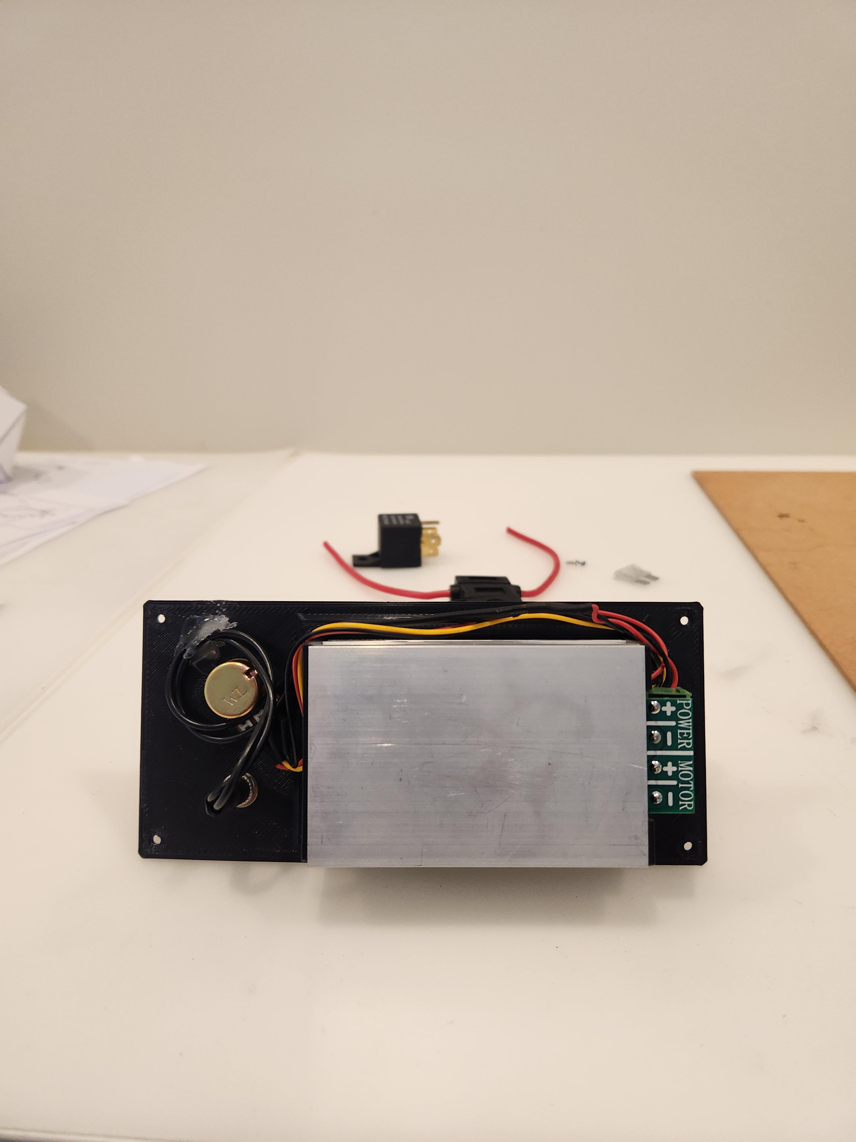
The Speed Controller


This step should be simple for you if you've thought ahead with what motor you will end up using. I changed mine last minute which led to some unnecessary complexity in my design (I had to add a relay that you do not need). I have left my wiring diagram attached above, but I also attached one titled "Ideal Diagram" which is the way I would have done this if I had known what motor I was using all along. You don't need to worry too much about all the other connections (as that is handled in a later step), but it is good to plan ahead!
First order a motor speed controller online that suits the specifications of your motor (consider the voltage type (AC, DC or 3-Phase), amperage, and voltage levels). My speed controller also came with a soft start feature which means that when powered on, it starts the motor at a slow speed, and builds up until it reaches the set speed. If you can, you should find a speed controller with this feature (as the lack of sudden jerk helps to increase the lifespan of all moving parts).
If your controller comes in a housing, you can skip the rest of this step so long as you also have a location for a 12V screw terminal block (as this will be connected to the fan that cools the motor). If yours doesn't come in a housing, you can modify my Fusion 360 file so that it suits your controller (Also consider increasing the wall thickness as I found it was a bit too flexible). You can also modify the text on the base so that rather than "12V 30A" it reads the correct values for your specific controller. You may also need to change the dimensions of the 2 holes on the front panel (one for the knob, and the other for the power button).


The button my speed controller came with didn't work. But I didn't mind as I had a few spare ones lying around and after all, I was buying a speed controller, not a button. I simply cut it off and soldered on a new one. You can then mount your speed controller to the inside of the casing alongside the potentiometer and power button.


You can quickly test your speed controller works by hooking up a small DC motor to the output and a power supply to the input voltage. With any luck, it'll work!
From there, you can leave a terminal block inside the housing that is attached to the input of the speed controller. Assuming you are also using a 12V DC speed controller, this will be connected to the fan used to cool the motor later on.
Making the Core Frame


Now that the electronics are out of the way, let's get back to welding! To make the core frame you just need a rectangular top with 4 legs. I chose to mitre the ends at 45 degrees because it looks beautiful, but you could just weld the top as butt joints if you wish. In one of the images, you can see a '+' made of black tubes, you can ignore this as it was the original frame design that I have since improved (with a 'T' as will be shown in later steps), the image does however show the layout of the mitre joints. To keep the rectangular top as flat as possible, I would recommend welding the outside and inside points first, and then the top and bottom faces (I found the welds pull the metal as they cool). It doesn't need to be perfectly flat as we will deal with that in the next step!
Adding Adjustable Feet


As promised, your bent, uneven frame doesn't matter! Heck, even if you cut your legs to different lengths it doesn't matter. To relevel our frame, we will add adjustable feet. Simply weld a nut inside a washer, and then weld the washer to the inside of the 4 legs. This allows us to screw in a bolt to varying lengths, and hence level our frame.


But we are more fancy than just bolts! Also, I didn't want to scratch every surface I put this machine on. You could just buy adjustable rubber table feet, but to save more cash, I figured I'd 3d print some that just slide over the ends of the bolts. I made two different styles, a tapered one and a rounded one. The Fusion 360 file is a parametric design, so you can just modify the user parameters to suit your bolt size. You can also play around with the other parameters to modify the height and size of the feet.


Once printed, you can just slide the 3D print over the top of the bolt, and it should tightly press fit over the bolthead. You may need to play with the tolerances to get them to work on your 3D printer.


Adding the 'T' Beam


Now that we have our frame nice and level, it is time to add a T beam to support the barrel holder. You can use some scrap parts to help lay out the design of the barrel and motor in their general places. I wanted the end of the barrel to slightly protrude past the end of the frame, but you can have it flush if you desire. Don't get too fixated on the position of the motor at this point (as we don't yet know the length of the coupler), just focus on the position of the barrel. The best part of this frame is that it is made modular, such that any components can be replaced or made differently, such as a different motor, or a different barrel holder.

Once you are happy with the layout of the barrel and barrel holder, you can cut some more tubing to size and weld on the middle T. Aim for the back of the T to be slightly further back than the flat angle iron of the barrel holder. You can then also drill the holes for the heater cables (you only need to drill through the top side of the tube, this will make more sense later). You should also drill 2 extra holes for the thermocouples, I forgot to do this and ended up wedging them through the heater cable holes. I used an oversized drill bit to chamfer the holes. This was my first time mig welding (as I had just saved up enough to buy one second-hand) so go easy on my welds as I try to figure it out :)


My only advice would be to take your time when welding the metal T to make it as square as possible. Trust me... it will make your life easier in the next step (unless you love sanding).
Additionally, we need to weld on some 'fins' for the barrel holder to bolt to. I used some thick (6mm) steel that was salvaged from the treadmill. Cut out two rectangular pieces and drill 10mm holes through both plates and the barrel holder. You can then bolt the entire thing together to check the fins are flush with the bottom of the barrel holder. If they are not, you can use the angle grinder to grind down the fins until they are flush. Then clamp the barrel holder to the frame in its final position, and tack weld the fins on. You can then remove the bolts and barrel holder, before properly welding on the fins. Make sure you don't weld the inside of the fins as it will stop the barrel holder from sitting flush when bolted into place.


Then bolt the barrel holder in position and drill another 10mm hole in the rear angle iron through both sides of the frame (you will need to remove the bearing if you have attached it already). This hole will house a third bolt for the barrel holder. You can see the hole in the images below.


Making Wooden Inserts


To fill the gaps between the T beam and the outer frame, we need some wooden inserts. This will give us something to screw into for mounting parts later. You could also just weld sheet metal to cover these gaps (as I do for some smaller ones later) but metal is harder to drill into and proves more difficult to drive screws into. The wood used came from an old tabletop which I picked up for free however, you could also use construction ply, pallets, or any other old wood lying around. I can only afford limited woodworking tools, but I borrowed a circular saw from a family member to cut the tabletop into a more manageable size. Then took that small piece to school to use a thicknesser to bring it down to 20mm. Then with a lot of sanding and the use of a drop saw I managed to cut four pieces to size and fit them into the gaps. You will need to round over the corners in order to accommodate for the shape of the welds. You can then screw the two pieces of wood together from the underside with countersunk screws.
You want the wooden inserts to be flush with both the top and most importantly the bottom of the frame (in my case 40mm thick).
The photos make this look simple and professional, but I won't lie... it wasn't. If I had more experience in welding, and a more professional welding bench than an old cement paver, the T piece may have been more square. Since the T was in fact not square... it meant a huge amount of sanding was needed to fit them properly. Don't we all love sanding...
We will add some metal tabs to screw the wooden inserts into (in a few steps), so for the time being you can remove them and leave them to the side (so that they don't get damaged or burnt from welding the rest of the frame).
Check Everything Fits


At this point, if you are anything like me you're dying to see it all put together (and praying it still all fits). So before moving on, you can bolt the entire thing together to check everything still lines up. You need to bolt it together in this order:
- Bolt the barrel to the barrel holder (using two M10 bolts)
- Bolt the barrel holder to the frame (using three M10 bolts)
- Then slide the auger into the bearing (Don't worry about the grub screw for the time being)
- Then slide the auger into the barrel (Don't worry about the alignment in the barrel, we deal with this in a later step)
- Loosely bolt the bearing to the barrel holder (Using 2 nuts or a locknut - this helps to account for any misalignment)
- Bolt the hopper to the barrel (Using four M5 bolts)
You can also hook up a battery drill (on the low-speed setting) to the end of the auger bit to check the barrel and bearing are still aligned properly. I also pushed the cables of the barrel heaters through the holes I have added a video of me testing this below.
Don't worry if the auger rattles around inside the barrel, as this will be prevented when molten plastic is flowing inside the barrel. Just make sure there is no metal-on-metal scraping.
Modifing the Frame


There are two modifications we need to make to our frame. First of all, we need to add some metal tabs to screw the wooden inserts into. To do this, cut 4 small rectangles from some sheet metal and weld them to the inside of the frame. Make sure that you weld them to opposite corners as seen in the images below (as this is the best way to fasten the wooden inserts). When you weld the metal tabs, make sure that they sit flush with the bottom of the frame, you do not want them sticking out. The easiest way to make sure they are welded flush is to rest the frame on an elevated flat surface (with the legs hanging over either side). You will need to use a rasp file or sand down the section of the wooden inserts that rest on the metal tabs to keep the wooden inserts flush with both the top and the bottom of the frame. You can then a drill pilot hole through each metal tab and into the wooden inserts to fasten a screw into (making sure you don't accidentally drill through the top of the inserts).


The second modification we need to make is to cut out 2 slots on the underside of where we drilled the heating element wire holes. This will allow us to later insert screw terminal blocks (through the large slot) and insert the power cables and thermocouples (through the small slot). I found the easiest way to cut these slots was to overcut the corners using an angle grinder, pull out the metal waste, weld over the corners (to replace the metal we overcut), and then finally use the grinding disk on the angle grinder to grind back the welds flush with the underside of the frame.


When considering the length and position of these slots you should consider two things. Since we are mounting the electronics box under the heaters, we want the large slot to be less than the length of the lid of the electronics box (this way the electronics box acts as a cover). Similarly, we want the small slot to be wide enough to fit all the power cables and thermocouples and be far enough away that it isn't covered by the electronics box when it is mounted (as this is the cable input/output).
The Motor Coupler


If you can find a (flexible) motor coupler that suits your motor shaft and auger bit online, buy it and skip this step. If you own a metal lathe or mill, you could probably make one yourself.
Failing that, you need to make your own coupling system. Conveniently, the auger bit has a hexagonal shaft (as they are designed to fit in drill chucks), this also means that we can fit a ratchet socket over the end of it. This idea comes from ianmcmill whose Instructable can be found here. If your motor has a threaded output shaft you are in luck! You can simply screw on a matching nut and drill a hole to insert a small rod/bolt as a keyway (to stop the nut from slipping off). I did this in my prototype when using a windscreen wiper motor from a car as can be seen below.


Then by using a piece of square bar, or cutting a socket extension in half and grinding a square end on one side, you can join the two ends of the sockets together!
If you don't have a threaded end on your motor you can either grind the end of it into a square (like I did on the incline motor), weld a socket onto the end of it (like I chose to do with the wheelchair motor), or if you have the tools, you can cut a keyway into both a socket and the motor. None of these methods are ideal, but they all work quite well. The best option is still to buy a flexible shaft coupler like the one in the image below. If you had a metal lathe you could possibly even resize the holes to suit your motor and auger.


Motor Mounting Brackets


Now that we know the length of the motor coupler, we know how far away we need to mount the motor. I wanted to be able to remove the motor once the frame had been built and the barrel holder had been bolted in place. This meant that I needed to allow extra clearance behind the motor. Mounting the motor isn't too difficult but you should take your time to make sure that the alignment of the motor's shaft and the auger bit is as close to perfect as possible. Everyone's motor will be different, but the general idea is just to add a cross beam (I had to cut a semi-circle out of mine), and then weld two supporting beams that you can bolt into. Your motor should (hopefully) have mounting holes.
If you are using a motor that has an output shaft parallel to the drive shaft (you can see mine has a 90 degrees gearbox, making the output shaft of the gearbox perpendicular to the motor's actual drive shaft), you could mount the motor on the underside of the frame, and then use pullies, sprockets or gears to link the two shafts. If you choose to do this method, you will need a different method of coupling the shafts. I would also highly recommend welding on a second pillow bearing where my motor is mounted (see the images above), such that the tension applied to the belt/chain is not applied as a bending force to the auger bit, but is rather supporting by a bearing on either side of the pully/sprocket. This would be a better option if you are using the main (large) motor from a treadmill.
Adding Sheet Metal


To cover up the two remaining gaps in the frame we can weld on some sheet metal (or you could make more wooden inserts if you'd prefer). First, measure and cut out 2 pieces of metal to fit each gap (one for the top, and the other for the bottom). I drilled a small hole in the plate that I was going to weld onto the bottom so that I could tip out any metal shaving and let out any smoke from welding. Then weld both the top and bottom plates onto the frame, using an angle grinder to grind them both flush afterwards. After tipping out all the metal shavings from the hole I had drilled in the bottom plate, I welded back over the hole and ground it flush.
Painting


Now that we've finished building the frame, we want to spray paint it to stop it from rusting, and because it makes it look beautiful. I sprayed mine black but you could spray yours any colour you like. Maybe try some different shades like a black frame with a grey hopper and barrel? Or maybe go colourful with a red frame and an orange barrel with a yellow hopper?? The sky's the limit with how you paint this, just try to cover all surfaces to give it the best chance against rust.
If you want to, you can also spray paint all the bolts, nuts, screws and washers. This is optional, but you should do it if you have removed the galvanisation (during the acid bath step).
You also need to paint the barrel, barrel holder, and hopper (if you haven't already). You will need to use high-temperature paint for the barrel as normal paint will burn off. I used BBQ/Engine paint from my local automotive shop.
Checklist


If you have gotten this far I am impressed. And guess what? You are almost there! This step is not just a copy of the supplies step (which focuses on where to get each component needed), but rather what subassemblies and parts you should have. So before we start the main assembly, you want to make sure you have all of the following parts:
☑ The main frame (with motor mounting points, barrel holder mounting fins, tabs for the wooden inserts, and slots for cables)
☑ Four adjustable feet
☑ Two wooden inserts and 4 screws
☑ The main electronics box (With loose cables for the heaters and a screw terminal for switching on/off the motor)
☑ The lid for the main electronics box, reinforced with a piece of thicker ply (if needed)
☑ The hopper and four M5 bolts and nuts
☑ The barrel holder and three M10 bolts and nuts
☑ The bearing and auger bit (You will see a small metal pipe in the images above, we cover this in a later step)
☑ A small metal pipe that fits over the shaft of the auger bit (As just mentioned, don't worry about this just yet)
☑ Two additional M10 bolts and 4 nuts (or 2 locknuts) for mounting the bearing
☑ The main barrel with two more M10 bolts and nuts + washers
☑ The nozzle, with a melt filter pushed inside
☑ 2 - 4+ Band heaters
☑ A motor and matching bolts to fasten it to the frame
☑ A coupler for the motor and auger
☑ An additional cable for connecting electrical earth/ground to the frame
☑ A power supply for your motor
☑ A speed controller for your motor
☑ A handful of small metal screws (mine were all salvaged but you could probably buy a pack of them)
☑ Insulation + Metal zip-ties (We will talk about this more later so don't worry too much for the time being)
☑ A PC fan + Hoseclamp (We will also talk about this late on)
☑ Both some thin and thick wire (for connecting the motor and fan)
☑ Some screw terminals (Around 4 will do - this is for connecting the heaters)
☑ Expanded mesh and/or sheet metal (This is used to make some safety guards and we talk about this towards the end)
☑ A short length of dowel (used for the push rod)
☑ Thick wire mesh (used for a hopper guard)
You will also need the following tools on hand:
☑ Pliers
☑ An adjustable wrench (or a spanner set)
☑ A Phillips screwdriver (for smaller screws that would be overtightened with a drill)
☑ A cordless drill with a Phillips bit (for wood screws) and a range of small drill bits (for small metal screws)
☑ A socket wrench (or socket screwdriver for smaller bolts)
☑ Soldering iron + Solder
☑ Your 3D printer (You didn't think we were done printing yet did you?!)
If you are missing something, make sure you go back and build/buy it before moving on. If I have written to not worry about it (or that we talk about it later) in brackets, you just have to trust me. You need it, but I will tell you why and the specifications as well as what options or cheaper alternatives you have in a later step so just keep it in mind but don't worry about physically having it right now. If you have everything else, then it is time to start the main assembly :)
Fastening the Wooden Inserts


Before you assemble anything else, you must add the wooden inserts. Simply push them into place and screw them in from the underside.
Mounting the Barrel and Hopper


Now that the wooden inserts are in place, we can bolt on the barrel holder. This is done with the two M10 bolts through the 'fins' and the one M10 bolt in the back. After the barrel holder has been bolted on, we can attach the barrel by bolting it to the barrel holder with another two M10 bolts alongside four washers. Then bolt the hopper on using four M5 Stainless steel bolts (you can use zink-plated bolts if you'd prefer). Make sure you have the nuts on the outside of the hopper, this means if they do rattle loose, they won't fall into your barrel but rather fall onto your table. I chose to have all the M10 nuts face the back, but that is just an aesthetic feature and isn't structurally required.


Next, we want to mount the bearing and auger bit. First slide the auger into the barrel and position it such that the end of the flutes (the spiral bit) lines up with the end of the hopper intake. If you cut your barrel to the correct length, the auger should be just shy of the end with the nozzle. To prevent kickback, we need the auger to push against the bearing. However, since the bearing is too far away from the tapered section of the auger bit, we need to cut a small section of scrap pipe (mine came from an old bike) to act as a spacer/bushing that is compressed between the auger and the bearing. This can be seen in the image below and is illustrated in red in the drawing.


You can then bolt the bearing to the barrel holder. If your motor isn't 100% aligned (which mine isn't) you can leave a small amount of room for the bearing to move by using a locknut, or 2 bolts which are tightened against each other. This can be seen below. Additionally, if your bearing has a grub screw, you can tighten that too.


Mounting the Motor


To mount the motor, drop it into place and slide the 3 bolts into place (don't tighten them yet). If you designed your frame correctly, you should be able to slide the motor far enough away such that you can add the motor coupler in whilst leaving the bolts in place. Once the motor coupler is in place, tighten the 3 bolts bit by bit (using locknuts) until the two shafts align as best as possible. If needed, you can add washers between the motor and the motor mounting bracket. If you don't have locknuts, I would recommend using split-ring washers to help prevent nuts from coming loose due to vibrations over time.
Extra Reference Images


This step just has a few extra images for reference. If you can't figure out how something goes together, please leave a comment and I will try to help clarify as best as possible. I will include any extra clarification images to this step if people specifically ask for them.
Wiring Up the Motor, Speed Controller & PSU


Due to me changing the motor I was using halfway through my design, my wiring became slightly more complex than it needed to be. This involved needing relays and additional components you do not need. Whilst I have attached my wiring diagram, I also attached an 'Ideal Diagram' which shows the way I would do this if I was starting from scratch. The ideal diagram has 2 different configurations, one for a motor that runs off mains power (240V AC in Australia and 120V AC in America) and one for a motor that runs off a DC voltage (I used 12V but you could interchange this for whatever your motor needs - Just be careful with the maximum voltage of your cooling fan if you indent to add one, more about this later on).
You should have a screw terminal block on the side of your electronics box that has the cables that are switched by the switch mounted on the panel of the electronics box (see Ideal wiring diagram). These will need to be wired over to the speed controller (as that is where I housed all the wires for the motor and fans). I have wired mine according to the original wiring diagram (the two cables carry a switched 12V DC - which then controls a relay in the speed controller housing), which is only because I changed my motor after I designed the electronics box. You should follow the ideal diagram.

The switches and/or LEDs should already be mounted to the panel of the main electronics box. You can connect the terminals of these directly, or with a screw terminal block (I opted for a screw terminal block which was mounted on the bottom-left side of the electronics box when we constructed the electronics box some time ago).
AC Motor (Mains Power)
By looking at the top of the Ideal diagram, we can see the AC motor wiring diagram. You need to run both live and neutral wires into a DPTS switch (make sure the poles are completely isolated). You can then run the output live wire through a fuse (as a failsafe) and into a 240V AC speed controller. The neutral wire can be directly connected from the output of the switch to the speed controller. If you want you can connect a 240V AC LED between the 2 output rails of the switch (after the fuse), as lights make everything look nicer! Then wire all the outputs of the speed controller to their respective locations on the motor. If you use an AC fan, you can directly connect it to the output rails of the switch (after the fuse). However, if you want to use a DC fan (like from an old PC), you will need to connect a transformer after the switch and fuse to step down and convert the voltage from 240V AC to 12V/24V DC (check your fan specifications). You can then connect the outputs of your transformer to the fan. Your transformer can be low amperage (like an old computer charger). You could alternatively buy an AC fan, in which case, you can wire it the same way but without the transformer. Remember to ground all metal components or anywhere an AC device has an earth socket.
DC Motor
The process is similar for a DC motor aside from you needing to immediately convert the voltage from 240V AC to your desired DC voltage (check your motor specifications - it doesn't have to be 12 or 24v, it could be 32v etc). Connect the positive output terminal from the transformer directly to the positive terminal of the DC speed controller (make sure the speed controller can handle the amperage requirements of the motor). Connect the negative output terminal of the transformer to a SPST switch, and then through a fuse (as a failsafe) and to the negative terminal of the speed controller. You could connect the fuse and/or switch to the positive terminal if you'd prefer since this circuit is standalone and fully isolated (it makes no real difference in this case). Then run the positive and negative wires from the output of the speed controller into the motor's respective terminals, such that the motor spins in the correct direction. If your speed controller is reversible, cut off that switch so you are not tempted to run it in reverse as this will destroy the barrel. You should solder it in such a way that it will only drive the motor in the correct direction, or leave the switch attached but don't house it in the control panel so you can't change its position. If your fan can run off the same voltage as the motor, you can directly wire it (and an LED if you want) into the input of the speed controller (i.e. the output of the transformer after the switch and fuse). If your fan requires a lower/higher DC voltage, you can use a buck/boost converter to step down/up the voltage respectively. Make sure all the cables you use on the output of the transformer to the speed controller, switch, fuse and motor are thick enough to carry the current your motor demands. You will likely need a high-amperage power supply/transformer for your motor. You can simply plug the power cable of the power supply into the socket we mounted in the back of the electronics box.
3-Phase
If your motor runs off 3-phase power, you will need to make sure you have that available and you'll need to figure out how to wire that based on the instruction manual of the motor.
Wiring Up the Heaters and Thermocouples


If everything else thus far has been done correctly, this step should be super easy. Take the two thermocouples, and 2 pairs of wires (one for the nozzle heater, and one for all the barrel heaters) and feed them through the small cable slot we cut into the frame earlier. You can then pull the loose ends out of the larger slot (as it will be much easier to wire them up). Then using a suitable screw terminal block (mine was rated for 20A, which is overkill), you can wire all the barrel heaters together to their respective power cables, and the nozzle heater to its power cable. It is a bit hard to see, but hopefully the photos above help to show what I mean. You need to push the barrel heater cables through their respective holes in the frame before you wire them into the screw terminal blocks.
If you drilled two extra holes in your frame for the thermocouples your life has just become easier! If you forgot like I did, you need to try and squeeze them between some heater cables. Make sure you put the thermocouple in the correct location, the nozzle thermocouple should be put next to the nozzle, and the barrel thermocouple should be put next to the middle barrel heater. Double check you didn't get them the wrong way around.

Mounting the Electronics Box & Speed Controller


Now that the wiring has been completed, we can mount the electronics to the frame. First of all, screw in the 6mm spacer to the top of the electronics box (from the inside) whilst the lid is still unattached. This spacer serves two purposes. First of all, it strengthens the lid as it is only made of 3mm ply (if you made it from anything thicker than 5mm you don't need to worry about this). And secondly, it creates a flush mounting surface as the screw heads aren't sticking up (if you used countersunk screws you don't need to worry about this).

Before we attach the lid, you can use it as a template to mark out where to drill the pilot holes in the frame. You will likely find the screws that hold in the wooden inserts get in the way of the lid. You can add a small amount of paint, or draw over the screw head with a sharpie, and then press the lid into its desired location. This way the location of the screw heads are transferred onto the lid (thanks to Make with Miles for teaching me this). You can see in the image above I used a counter-sinking bit to drill out a recess for the screw head so the lid can sit flush with the frame. Then simply press and screw on the lid to the main electronics box, and then screw the electronics box onto the underside of the frame.


When it comes to mounting the speed controller, all you need to do is drill some holes through the casing into the frame and then screw it in. You could modify the 3D file to add mounting points, but I chose to just screw it in directly.

Earthing


This may be a short step but cannot be overlooked. You must ground/earth any conductive part of the machine. Luckily for us, everything that is conductive is touching. This means we only need one earth wire to the frame. We left a bolt out the back of our electronics box earlier that was wired to earth, which conveniently allows us to simply wire a jumper cable between the frame and the bolt. I sanded back a patch of bare metal for the earthing screw to connect the wire against (although it gets covered up by the head of the screw so you can't see it in the image above). Use a multimeter on continuity mode to make sure the entire frame and all metal components are earthed correctly. If you find that a piece of metal isn't earthed (due to paint blocking the current flow or similar), simply wire a second earth cable to that piece of metal.
Cooling the Motor


Depending on your motor you may or may not need to do this step. My motor is designed to run continuously but I chose to add additional cooling to help improve the lifespan of the motor. To do this, I simply designed a fan mounting bracket in Fusion 360 and 3D printed it. The mounting bracket works by using a standard 12mm hose clamp (the length is dependent on the size of your motor). You can also change the size of the fan you use by simply modifying the size of the mounting plate (mine was 80mm).


After printing off all the parts, you can slide the 2 braces onto the hose clamp. You may need to experiment with printing tolerances if the braces don't slide over your specific hose clamp. The order you slide the braces on is dependent on which direction you want the screw on the hose clamp to face once fastened to the motor.


The fan plate can then be screwed on using 3 small screws. Finally, mount a 12V DC fan to the plate using larger screws (you don't need to use 4, you can see I only used 2 which are diagonally positioned). Then wrap the hose clamp around your motor and tighten it such that the fan inlet faces the side or back. I am not sure if it is more advantageous for the fan to push cool air onto the motor or suck hot air away from the motor, but I chose to orientate the fan such that it pushes cold air onto the motor. If you have a wire guard, you can screw that onto the front of the fan to prevent things from getting caught in the blades, you could also 3D print one (there are tons of designs online and it is easy to make your own).


You can run the cables from your fan into the back of the speed controller. If you wired your speed controller as I did, you should have a screw terminal block connected to the input of the speed controller. You can wire your fan into this terminal block. Make sure you get the polarity of the wires around the correct way, with the positive wire (red) to positive, and the negative wire (black) to negative.
Now when you turn on your motor you should hear the hum of a fan!
Mounting the PSU


If your PSU comes with mounting holes or a mounting bracket that is the best way to secure it to the frame. Otherwise, you could design and 3D print a mounting frame for your specific PSU. However, I decided that small 3D-printed brackets would work best as a more generic solution. These brackets are designed by 3D_Workspace and the original files can be found on printables (you can find original copies and more information by following the link in step 4).
After printing off 3 brackets, you can drill small pilot holes in the frame and the side of your PSU. Be careful where you choose to drill holes in your PSU and make sure you don't damage any internal components. You can then screw the brackets into your PSU and finally into the frame. I printed the brackets at 20% infill with the fuzzy feature enabled in Cura for a cool texture (this is entirely up to personal preference).
 →
→ 
Insulation


Do not overlook the importance of insulation. It not only saves a ton of power (which saves you money), but it keeps the internal barrel temperatures more consistent and the external barrel temperatures much lower (reducing the chance of you burning yourself). High-temperature insulation is expensive and hard to come by in Australia (or at least where I live), this meant I needed to get creative. If you can buy Rockwool or another commercial insulation, you can simply zip-tie it to the outside of the barrel (using metal zip-ties) and cover it with aluminium foil. Otherwise, I found two cheap alternatives.
- A fire blanket. In my first prototype, I used an old fire-blanket which I trimmed down to suit my barrel and then used wire to hold it in place. This worked surprisingly well but made cabling difficult.
- Exhaust Wrap. This is what I decided to use for this machine. I bought a roll of motorbike exhaust wrap online (for around $10) and wrapped it around the barrel, weaving around the cables. I guesstimated the length I would need and then cut four times that length and folded it into a single length with four times the thickness. Starting at the nozzle, you can then wind it around to the hopper, using metal zip-ties to secure it as you go. If you have fibreglass wrap, do not soak it. There was a mix of opinions online about whether you should soak fibreglass wrap, and I can tell you it is a bad idea. First of all, we do not need a perfect wrap (as the extruder will not be exposed to high speeds and weather as a motorbike would). But second of all, the black dye leached out causing a mess and making the whole process harder than it needed to be.
Regardless of what method you choose to do, fibreglass fibres will get everywhere and they are almost impossible to see. Wear gloves and a mask to prevent inhalation, and wear old clothes you can dispose of if you need to. Do this outside.
Once you are finished, I would highly recommend spray painting the insulation with any left-over high-temperature paint. The more the better. The fibres will absorb the paint and it sticks them together. Using a glove, or a scrap piece of wood, you can press down any fibers that are sticking out to help 'glue' them into the main insulation. This just helps to prevent them from spreading everywhere over time.
Calibrating and Setting Up the PIDs
Rather than writing out a long and complicated list of steps on how to set up and then calibrate the PIDs, I thought I'd link to some super useful videos below. I did not create these videos, but they do the job so well that'd be pointless making my own. If you are using different PIDs you'll have to refer back to your instruction manual.
How to set up the PID and what each setting means (Credit to Barley and Hops Brewing)
How to calibrate the PID (Credit to GreenLeader)
Temperatures

All types of plastic have their own melting points. It is super important to keep the individual types of plastic separate so that they can be recycled again and again. As a rule of thumb, I found that setting the nozzle to 5 or 10 degrees higher than the barrel works well for a smooth output, but you should play around with this value. You can simply look up the melting point of your specific type of plastic is online, but Dave Hakkens created a super cool visual poster that shows it way better than numbers ever could. You can see that above and you can find more of his information on his website (definitely worth the read). He also has a forums post that talks more about it here.
Dave Hakkens (who started Precious Plastic) also has super important information about fumes and how to avoid burning plastic. Not only is it bad for the environment, but you definitely shouldn't be breathing it in. That is also worth a read here.
Some plastic is too toxic to recycle at home. Generally, I'd stick to type 2 (HDPE), 4 (LDPE), and 5 (PP) and recycling failed 3D prints (Although be careful with ABS). There is more information on Precious Plastic's site here.
Dave Hakkens has done so much research into the topic and has super helpful tutorials (that may use a few complex tools or go slightly over my budget) but he still provides an amazing resource. He was a major inspiration for this project so a huge thanks goes to him, and if you can, I'm sure he'd appreciate any donations.
Something to consider with the extruder is it isn't just the temperature that matters. The motor speed in combination with the temperature is what you need to manage. For example, HDPE melts at 132°C but I heat my barrel up to 185°C as I know I am pushing it through fast enough that the plastic doesn't even reach 132°C by the time it gets forced out of the nozzle.
A rule of thumb is that the slower you push the plastic through the barrel, the more accurate the temperature reading will be of the plastic inside the barrel. The faster you push the plastic through the barrel, the cooler the plastic will be compared to the temperature of the barrel.
Since every machine is different, the temperatures from one machine won't perfectly match up with another. The only way of really doing this is testing. Once you find the best speed and temperature for a type of plastic, write it down and begin your own plastic journal! Maybe we could even use recycled plastic to make a journal cover... and use recycled paper for pages... now that's an idea :)
It's Alive!! (Hopefully)


Before we start making the machine safer and making it look nicer... it is best to test it works. Since there are no protective guards, and we have loose cables lying around, make sure you are out of harm's way before turning anything on. I would also recommend wearing some silicone BBQ gloves to protect your hands from the heat of the plastic. Plastic retains its heat for a surprisingly long time.
Start by turning on the heaters and wait until they get to temperature, then pour in some shredded plastic flakes and get the motor spinning. Start on the slowest speed and adjust as needed.
If all goes well you should be making some tasty-looking noodles! (Please don't eat them)
You can see a video of my first test run below. The reason it is extruding so slowly is I didn't have enough plastic on hand to fill the barrel (I melted some of the extrudes from my prototype in this test - made from HDPE bottle tops). I would recommend watching it on 2x speed. Sorry about the poor lighting :)
Cable Management


No one likes a bunch of loose cables. To fix this I designed some cable management clamps in Fusion 360 that can be screwed into the underside of the frame. I used 2 small ones for the 12V cable that runs between the main electronics box and the speed controller, as well as a medium and large clamp for the power supply cord to the PSU. You can see the arrangement I chose above, but feel free to customise it however you want.

Pipe Caps


The 2 open pipes that we mounted the motor to are starting to collect dust... time to cap them off! To do this all we need to do is open Fusion 360 and model up some caps to then 3D print. I have designed a parametric model so that you can change the parameters to suit your pipes, and it should generate a perfect pipe cap for you.

The comments explain the parameters pretty well so I won't go too in-depth with how to customise them. One extra parameter I added in a later version was "angle" and this is simply because the pipe we cut on an angle for the motor to mount too won't work with a normal pipe cap. This is because normal pipe caps assume that the length of the pipe is (close to) 90 degrees to the cut of the pipe. However, since ours is not 90 degrees we just need to cut away a slight portion that matches the angle of the pipe. To do this, update the user parameter, and then right-click on the faded features in the timeline to un-suppress them and Fusion 360 should handle the rest. Make sure you use the acute angle (less than 90 degrees) and just know that if you don't want any cutout, suppress the feature (as setting the angle parameter to 90 degrees will cut away the entire cap).


Remember, if your pipe has been cut on an angle, the top face that we need a cap for is no longer the same size as the regular pipe, as the length is now longer. So make sure you measure it first!
After you have made and exported your custom pipe caps, just print them off and wack them onto the top of your pipes! Take that dust!

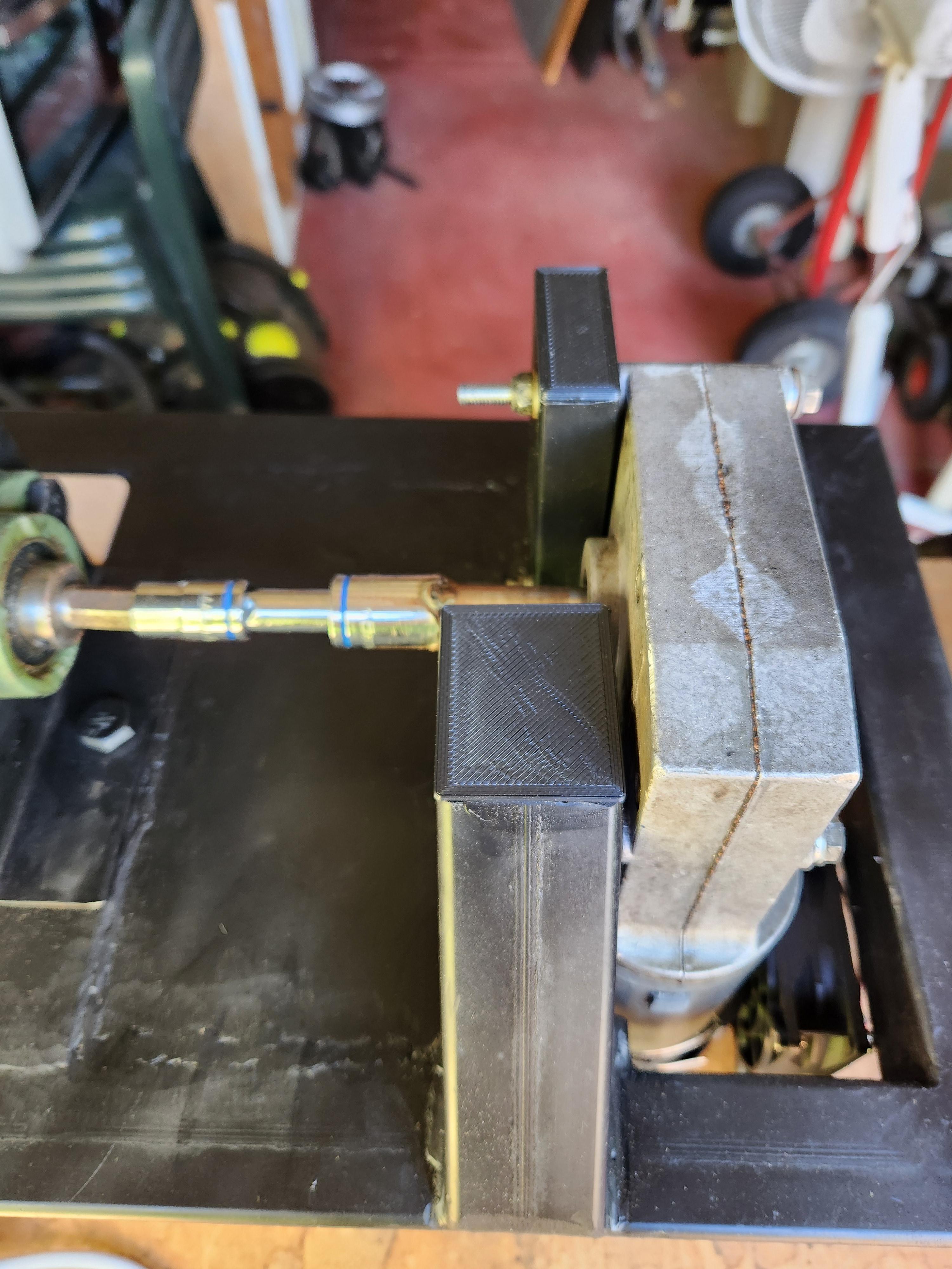
Protective Gaurds


I know what most of you are probably thinking... Not only will I get burnt, but there are also moving parts for my clothes and hair to get caught in! Luckily, the insulation already lowers the external temperatures hugely, but in saying that, we don't want to touch the fibreglass either. We just need to add a few protective guards to solve these issues.
If you have sheet metal lying around, you could fold some hexagonal-shaped guards using a sheet metal brake and these would not only work a treat but also look cool (in my opinion). I don't currently own a sheet metal brake, so I opted to use mesh as I could bend it much easier without any tools. I plan on designing a DIY sheet metal break and will post an instructable if I get around to it (and include a link here if I remember).
We need to make two guards, one for the motor shaft, and the other for the barrel. To start, I cut the mesh off an old broken pedestal fan. I then bent it by hand into the rough shape I was aiming for. Then using tin snips (or an angle grinder), you can trim the mesh down into two rough shapes (One is a simple U and the other is a larger U but with a curved end - as the barrel protrudes past the frame).


For the motor guard, since it won't be exposed to any heat I decided to just 3D print a casing that the mesh inserts into. The two U-shaped brackets can first be pressed onto the sides of the mesh. Then you can screw the base under the motor shaft, and press the mesh and U brackets into the base. Finally, using four small screws, you can secure the two segments together.


This was a quick and easy way of making the guard, and I will likely replace it with a sheet metal one in the future (just for aesthetic reasons).
Since the barrel protector might get a bit warm (and I only had PLA on hand), plastic won't do... this means we will need to do some welding! Turn down the heat/power on your welder. It is way too easy to burn through this thin mesh. Make sure you test your settings on some scraps first. Then using a section of the original ring we cut off the mesh, as well as some strips of scrap metal, we can weld some metal framing to the mesh. The reason we do this is not only for strength but because the mesh has very sharp points where we cut it. I found it easiest to slightly unfold the mesh to weld on the top and bottom strips. Then after rebending it, I cut some scrap L-shaped lengths of steel which act as a surface for us to drill mounting holes. After drilling through the side brackets we just welded on, we can also drill pilot holes into the wooden inserts (either side of the main barrel). All that is left is to spray on a quick coat of paint. I used high-temp paint as I had some left however, you can just use ordinary paint as the mesh shouldn't get hot when in use - otherwise we would need a heat guard for the heat guard :)


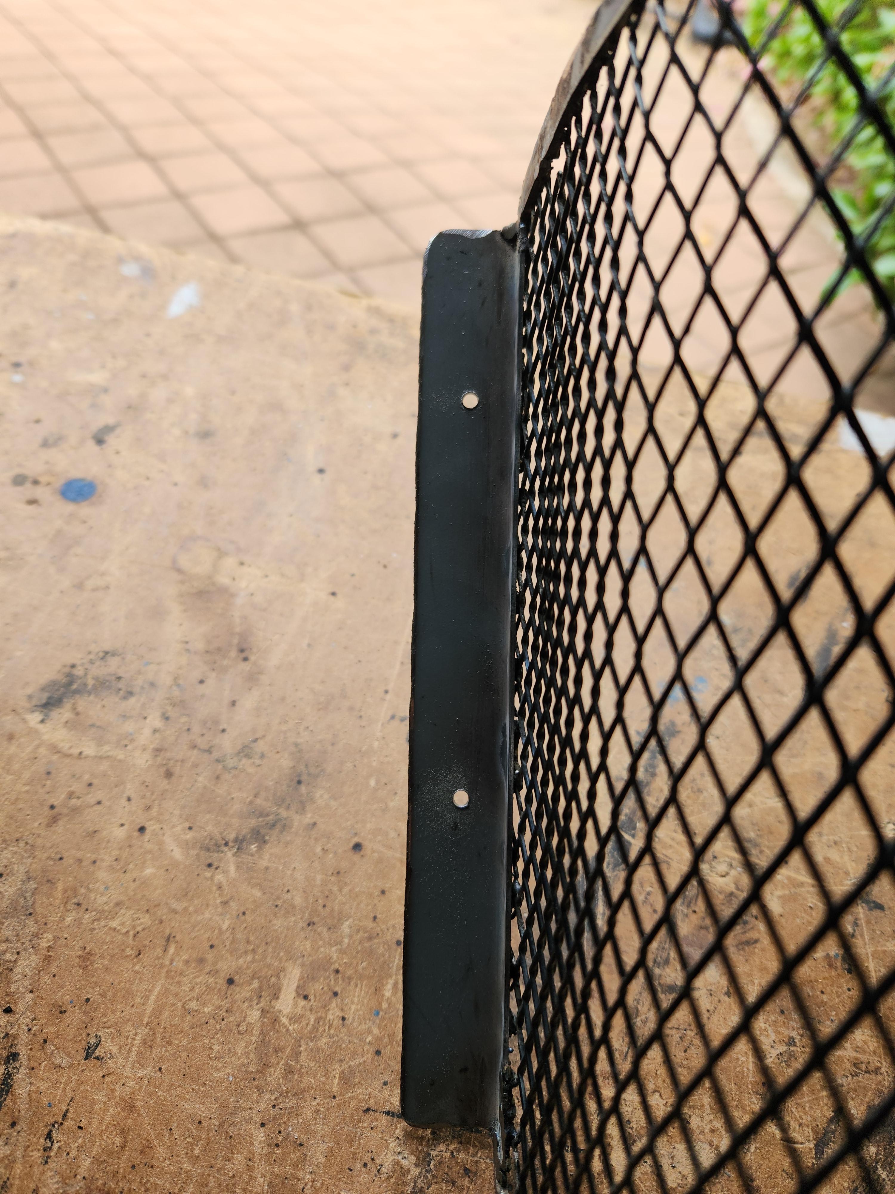


Bravo! Now there are no more obvious safety hazards... except the spinning auger bit, we can stick our fingers into.
Hopper Gaurds


I don't want to lose my fingers by accidentally getting them stuck in the auger bit. To solve this issue, we can add a thicker mesh on top of the hopper to prevent people from sticking their hands into the hopper, whilst also leaving large enough gaps to pour plastic in, and use a push rod (see next step) to help make sure the plastic chips are falling in. You can find mesh from old concreting wire, mesh baskets, shoe racks, etc. By laying the mesh on top of the hopper (or removing the hopper and laying it on the mesh if your mesh sheet is too heavy or large), you can mark out the size of mesh you need to cut. Try to cut it so it doesn't leave sharp points (this is hard to explain but you can see how I cut mine in the image below). Then spray on a coat of paint and we're almost done!


To attach the mesh to the hopper, you could simply weld it in place, but I wanted to be able to lift the mesh like a lid in case I needed to reach inside the hopper (when the machine is turned off) to service something. Also keep in mind, that if you weld the mesh onto the hopper, tightening the 4 bolts used to hold the hopper in place will be super tricky. I used Fusion 360 to quickly model up a hinge that could be pressed onto the side of the hopper, and clip over the side of the mesh. The mesh rectangle I cut sat 10mm down the side of the hopper, had a wire thickness of 3mm and my hopper is made of 1mm steel. You can modify the Fusion 360 model to suit your parts as needed, or simply scale the part in your slicer.


To assemble the 'hinge', just print off as many clips as you need (larger hoppers will need more clips), then snap them over the wire mesh. After they are on the mesh, you can push them all down over the side of your hopper. They are designed so that the clip is tapered, this way the clip will clamp onto the side of your hopper.


Push Rod


Since plastic chips are an inconsistent shape, they can sometimes get stuck and not fall into the auger. To solve this we need a push rod. This allows us to manually push all the chips down from time to time. A future upgrade would be a small machine that you could make and clip onto the edge of the hopper, which would then slowly turn and mix the plastic around
If you are interested in this concept, you could consider using an old synchronous motor (from the turntable of a microwave) or a geared DC motor, then design a 3D-printed housing and wire the motor directly into the 240V AC or 12V DC terminal block on the left-hand side of the electronics box (depending on the voltage of the motor), this way it will only be turned on when the motor is in use. Attached to the motor's shaft, you could have a large spring/coil-shaped piece of wire. If you do make this, please share it by posting a "make" below and I will credit you and include an additional step with your notes and photos! I intend to design this myself in the future so that there are no manual inputs required to operate the machine.
For the time being, all we need is a simple dowel rod. To prevent us from accidentally getting the dowel stuck in the auger as it is spinning, we can insert it through a piece of wood that will rest on the mesh hopper guard. We can then cut the dowel just shy of the auger so it can't possibly get stuck! It is a bit hard to explain this in text, so I have attached a drawing below.

Making this is simple. I wanted a circular piece of wood on the top of my dowel, but you could have it any shape you want, so long as it is larger than the holes in the mesh on top of your hopper. I first took the largest hole saw I owned, marked out the centre of the bit, drilled a pilot hole, and then cut out a circle in the excess wood I had leftover from making the wooden inserts. To avoid chip-out, you should cut halfway through the piece of wood, turn it over and then finish the cut from the other side (This is why a pilot hole is so important).

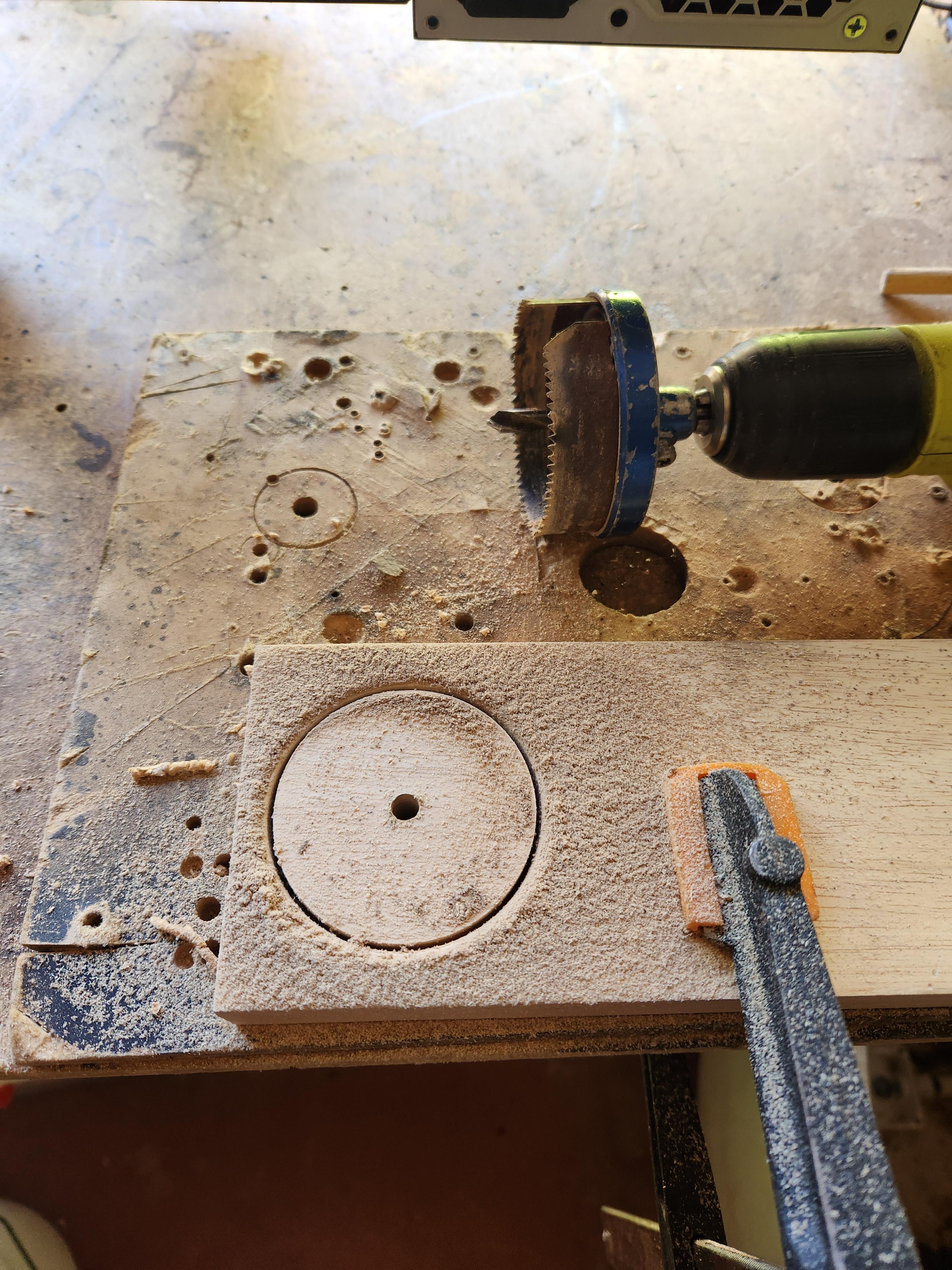

I then inserted a bolt through the pilot hole, tightened it into the chuck of my drill, and then sanded it smooth on all surfaces, and added a slight chamfer on the edges.


Next, drill out the pilot hole to the correct size for your dowel rod. After press fitting the dowel into the top, you can use a small drill bit, to carefully drill out a hole in the end of your dowel that is pressed into the circular piece of wood. Using a large countersinking bit, you can then chamfer this hole, allowing us to insert an oversized screw that sits flush with the top. You want the screw to be oversized so that it acts like a wedge, forcing the dowel outwards into the circular piece of wood and securing it in place without glue (in case you need to modify or replace the dowel rod).


If you'd prefer to just glue the dowel, you can also do so. I opted to do that for the pushrod I designed for my prototype as can be seen below.


Then measure the distance between the top of the auger and the mesh protector of the hopper and cut the dowel to that length (or an inch/2cm shorter to be safe). You want to measure the length at 90 degrees (i.e. straight down) to the mesh guard so you get the shortest possible length. I have re-embedded the drawing below to hopefully clarify what I mean (green text).

Power Cable Holder


After building such a beautiful machine, we don't want to just leave our power cable dangling around when not plugged in. I also don't want the hook to stick out, otherwise the machine becomes harder to store and more likely for someone to run into the hook and break it off. That means we are jumping back into Fusion 360 once again! I designed a quick and easy cable hook in a few minutes, printed it off, and screwed it into the underside of the frame.
I also ended up welding a small metal hook to the underside as I wasn't sure which I preferred (so why not have both). I would highly recommend welding on the metal hook while you are still building the frame if you think this is what you'd prefer.
Cable tripping crisis averted! And would you believe it? We are done!!
Shredding Plastic
This extruder needs shredded plastic to work, so you'll need a shredder. This is a huge topic all on its own and I will post an entire Instructable on that in the future. The shredder is more complex, dangerous, and expensive than this machine so it has taken a long time to develop, and my version is currently not safe enough for me to share build files. In the meantime, there are a huge number of people who have undergone experiments on how to build plastic shredders and you can find them all on YouTube or online. Precious Plastic has great instruction files, but his design is slightly more expensive than I can afford and requires expensive machinery.
You could cut the plastic by hand or use a cross-cut paper shredder for the time being. I managed to find a YouTube video that is similar to the start of my journey, although I am still looking for an alternative to the expensive gearbox. Once my design is more finalised, I will post another Instructable. As mentioned, there are already a large number of solutions online that may suit your needs for the time being (however most require complex machinery or cost a fair bit).
Plastic Pellets

I am curious to know if using plastic pellets provides a more consistent and reliable output than shredded flakes. I will update this step in the future with my findings. You could extrude a 'rough' filament by pushing out as much plastic as possible as fast as possible and just letting it fall into a bucket of water (or cut it hot? Which would likely need less force). Then chopping up the entire thing (with a grandulator or similar) back into pellets to be run through again. The advantage of this is that the plastic pellets will have less air between them than plastic chips of the same volume. If you experiment around with this, please let me know your results in the comments.
It may also be just as effective to shred your plastic into a smaller size. The shreds I am using a quite large as my shredder doesn't have a mesh so large chunks of plastic can fall through.
(Credit to Precious Plastic for the beautiful photo above)
Final Comments


Congratulations on making it this far!! If you have made your own extruder please send me a photo or post a make below! I would love to see and learn from it, not to mention you should be super proud of your creation :)
This machine was made with 3D filament in mind, but you can also use it like a conventional extruder. This means you can make beams, lampshades, wrap handles of tools, or fill aluminium moulds. I will likely post another instructable soon on how to do some of these things (So if you have any cool ideas please leave a comment and I will make sure to include them - I will also include your username & comment). However, the next big project will be the winding mechanism for cooling and making the filament. If either of these projects interests you, or you want to see other engineering, programming, or circuitry projects you can follow this account so that you don't miss their release :)
Until then!
Bonus Photos!


Even the birds are excited about recycling!