Love-A-Meter Instructable
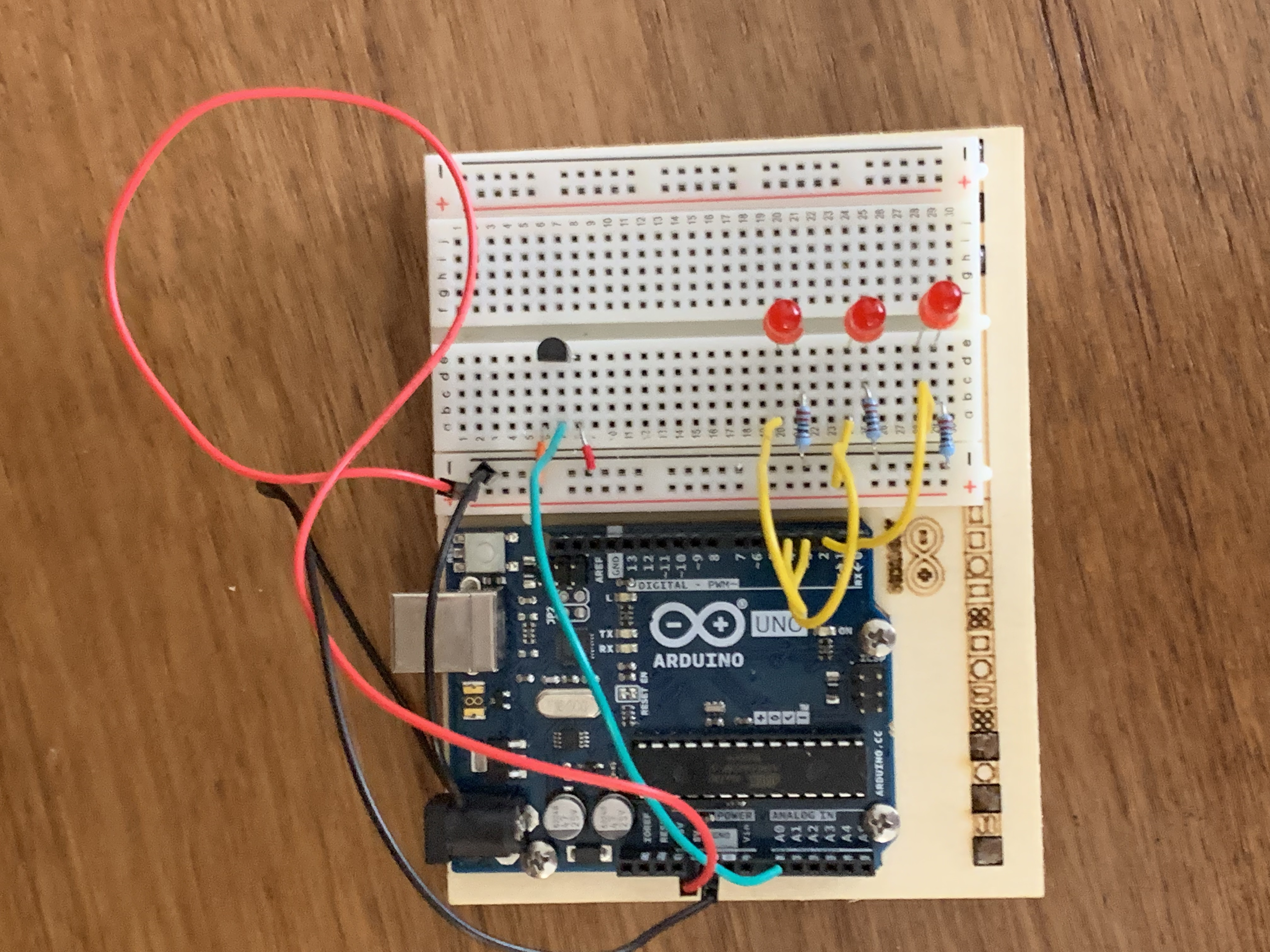
Have you ever wondered if a person is truly in love with you, with just a simple visual reference? With this project, you will be able to accomplish that! You will turn the Arduino into a love machine. With this circuit, you will be able to know how hot you or another person really are!
Supplies
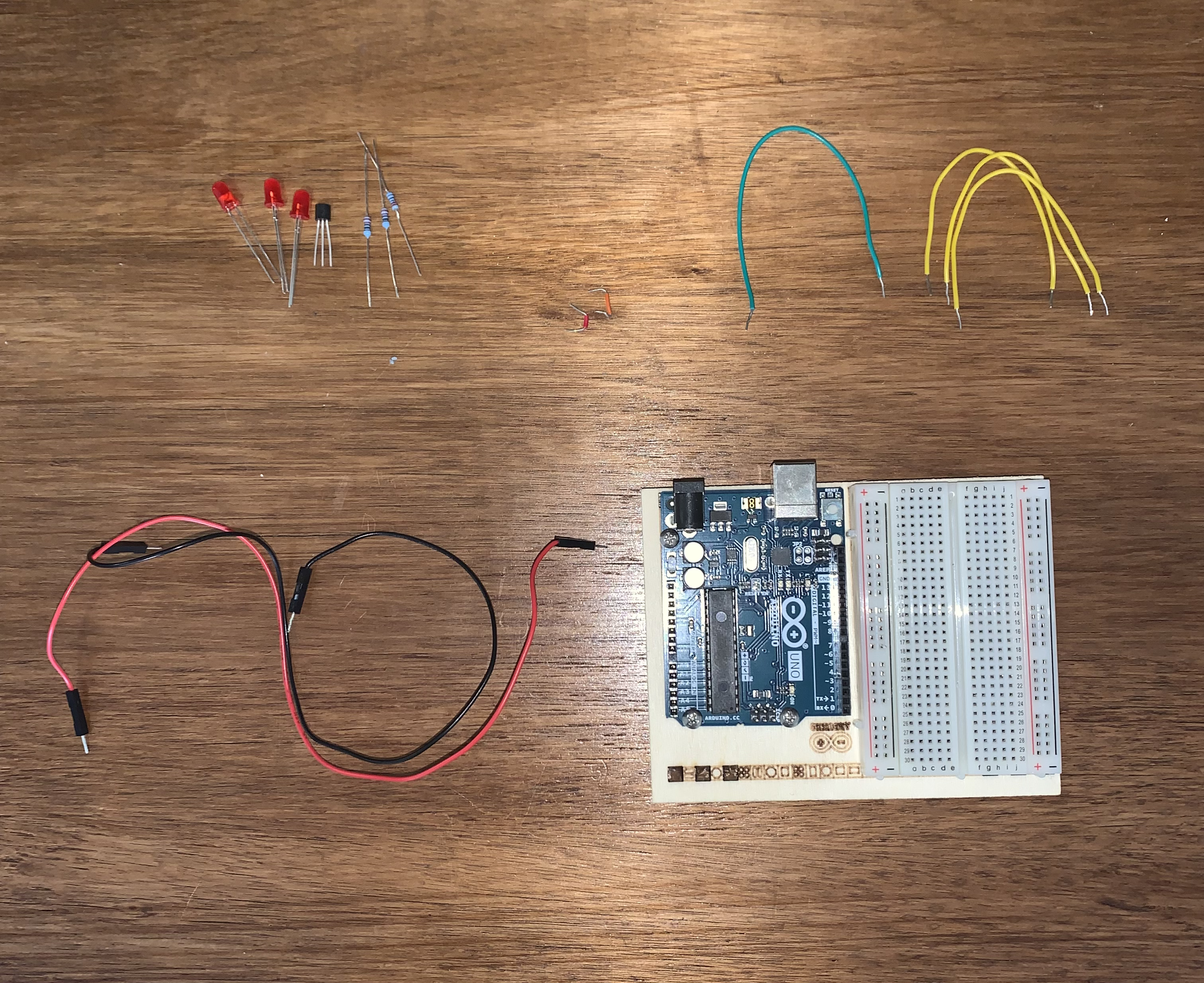
The project includes a lot of different parts, which include:
- 3 Red LEDs
- Three 220ohm resistor
- One TMP36 temperature sensor (check the label)
- Multiple-sized wires
- One breadboard
- Arduino One.
A special element of this project is the temperature sensor which, in this project, will measure the temperature of your skin. This component will send a different voltage depending on the temperature it senses. This element has 3 pins: one to connect to the ground, another one that connects to the power, and the third that sends the voltages to the Arduino. In this project, the temperature sensor will be used to measure the temperature in your hand a turn on a different amount of LEDs depending on your temperature.
Getting the Materials
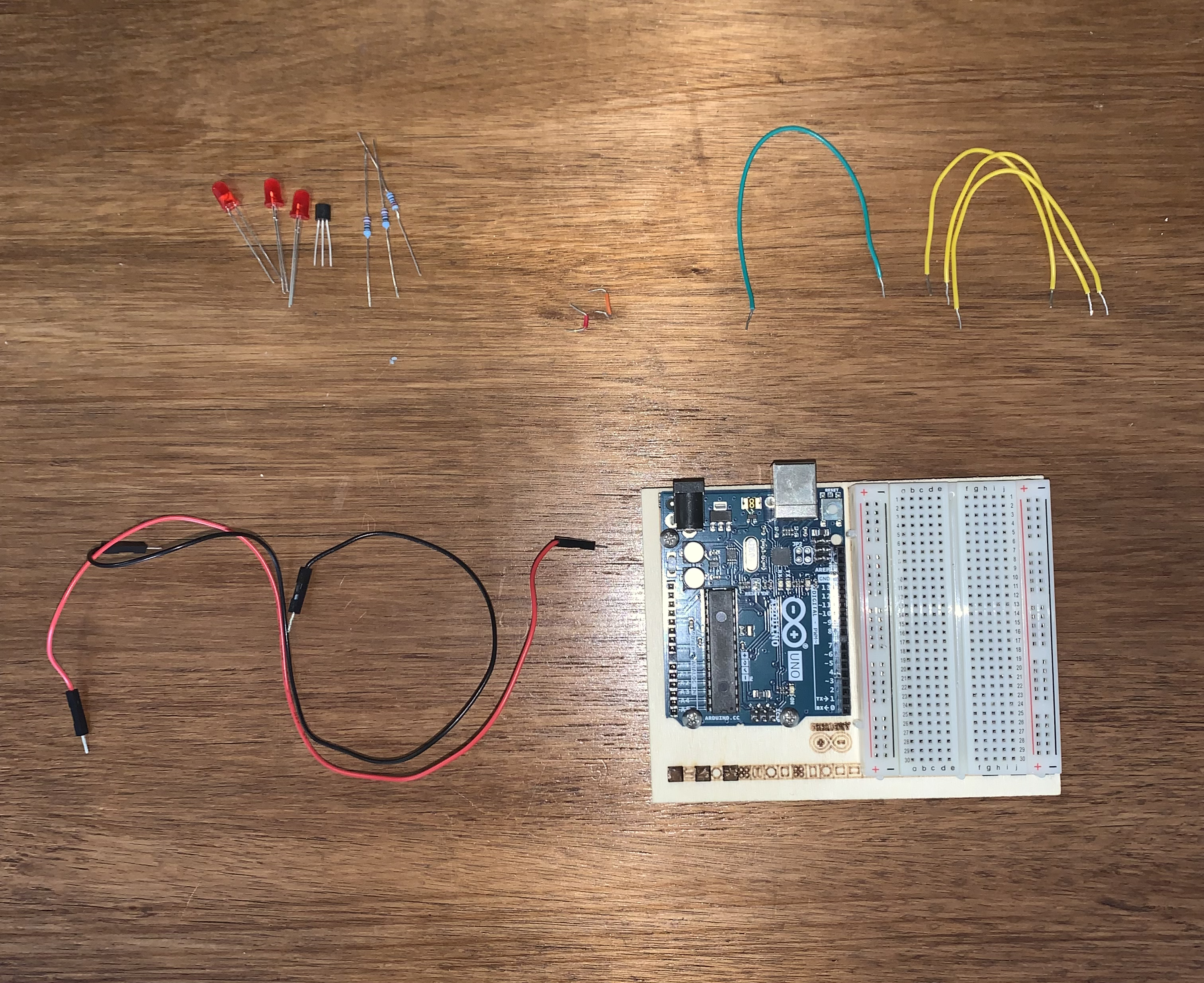
To begin the construction of the love-a-meter, you must take all the materials shown in the picture, the breadboard, the Arduino, the resistor, the wires, the LED´s, and the temperature sensor. Don´t forget any material as it will be vital for the progress of your project.
Connecting to Power
 14.49.42.png)
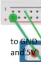
You have to wire up the breadboard with power and ground as in the previous projects. Just as you’ve been doing in the earlier projects, wire up your breadboard so you have power.
Connecting the LEDs.
 14.49.50.png)
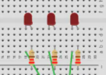
Once you have completed step number 3, you have to attach the cathode (short leg) of each of the LEDs you´re using to ground through a 220-ohm resistor. Connect the anodes of the LEDs to pins 2 through 4. These will be the indicators for the project.
Placing the Temperature Sensor
 14.50.01.png)
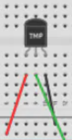
Once you have finished with the last step, you must place the TMP36 on the breadboard with the rounded part facing away from the Arduino (please revise that your pins are placed correctly) as shown in the image below. Connect the left pin of the flat facing side to power, and the right pin to the ground. Connect the center pin to point A0 in your Arduino. In this case, it is analog input pin 0.
A Pair of Useful Constants
 20.14.09.png)
On the code, constants are similar to variables since they allow you to uniquely name components of your program. In contrast to variables, they remain the same. For easy reference, name the analog input, and create another named constant to bald the baseline temperature. For every 2 degrees above the baseline, an LED will turn on. You've already seen the int data type, used here to identify which pin the sensor is on. The temperature is being stored as afloat. This type of number has a decimal point which can be used for a number that can be expressed as a fraction.
Initialize the Serial Port to the Desired Speed
 20.16.36.png)
In the setup, you are going to use the command named “Serial.begin( )” which opens a connection between the Arduino and the computer, so you can see the values from the analog input in your computer screen. When writing 9600 in your code, you are saying the speed at which the computer will communicate, in this case, 9600 bits per second. For this project, you will be using the Arduino IDE´s serial monitor to view the information you choose to send from your microcontroller.
Initialize the Digital Pin Direction and Turn Off
 20.18.55.png)
The “for( )” variable works by setting some pins in your board as outputs. Instead of having the necessity of giving each LED a unique name and typing its pinMode, you can rapidly loop through them quickly with the “for( )” function. In this case, you will use the past mentioned function to go through pins two to four sequentially.
Read the Temperature Sensor
 20.19.04.png)
In the loop( ), you´ll use a local variable named sensorVal to store the reading from your sensor. To get the value from the sensor. you'll call analogRead( ) that takes one argument: what pin it should take a voltage reading on. The value, which is between 0 and 1023, is a representation of the voltage on the pin.
Send the Temperature Sensor Value to the Computer
 20.19.07.png)
With the function of “Serial.print( )” you can send information from the Arduino to the serial monitor in your computer. In other cases, by typing an argument with quotation marks, you can make the text appear as typed, or you can give a variable in an argument and make the value of the variable appear.
Convert Sensor Reading to Voltage
 18.18.48.png)
 18.18.58.png)
In this code, you must store the value for the voltage inside a “float” which can be made by creating a variable named voltage to hold the voltage number. You can divide 1024,0 and multiply by 5.0 this number, which will give as a result the voltage on the pin. This value will be shown on the serial monitor.
Convert the Voltage to Temperature and Send the Value to the Computer
 20.19.20.png)
When seeing the sensor datasheet, you will see the range of the output value. The datasheet for this sensor shows that 10 millivolts of change from the sensor are equivalent to a temperature change of 1 degree Celius, and also indicates that the sensor can read temperatures below zero degrees. Because of this detail, you must have an offset for values below zero degrees. For doing this, you take the voltage and subtract 0.5 and multiply by 100, which will give the accurate temperature in degrees Celsius. This value must be stored on a floating-point variable named temperature. The real temperature must be printed out in the serial monitor too.
On the code, the temperature variable is the last thing that you are going to show in your loop. Therefore, you are going to use the command “Serial.println( )” which will create a new line in the serial monitor after it sends the value.
Turn Off LEDs for a Low Temperature
 20.19.25.png)
With the true temperature, you can use the function “if( )...else” statement to light the LEDs in which you will use the baseline temperature as a starting point, in which you will turn one LED for every 2 degrees that the temperature increases from the baseline.
Turn One LED for a Few Temperature
 20.40.10.png)
In the code, you will notice the statement “&&” which means “and” in other words. Using this function can let you check multiple conditions.
Turn on Two LEDs for a Medium Temperature
 18.19.26.png)
On the code, if the temperature is between four to six degrees above the baseline, the code will make a block of code which will turn the LED 3 on as well.
Two on Three LEDs for a High Temperature
 18.19.39.png)
In the code, you must write a small delay at the definite end of your “loop( )” since the Analog-to-Digital converter has a limited reading speed. This will make the values easier to read.
Test It Out!
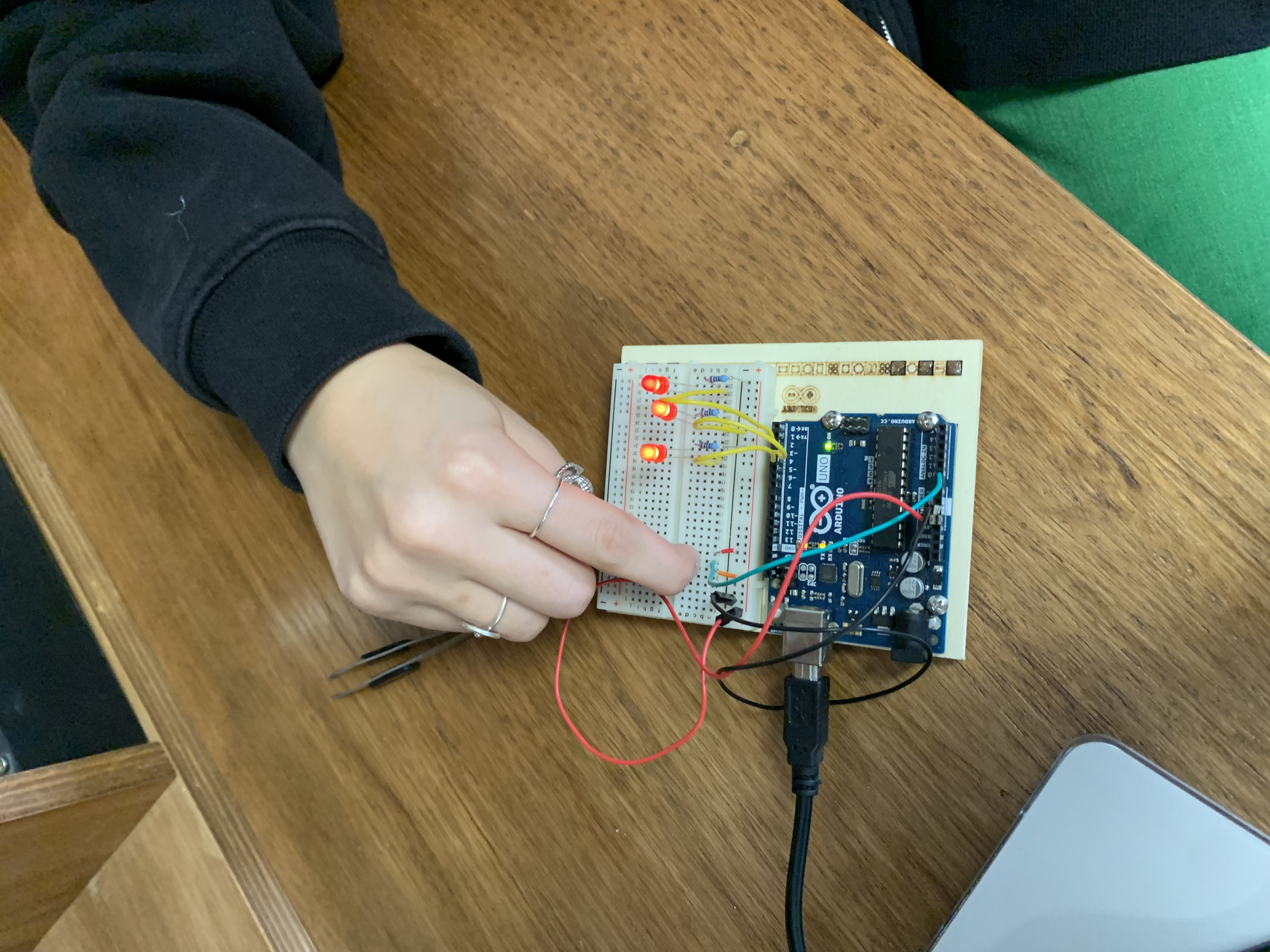
Once you run your Arduino with its code, you should click the serial monitor and see a stream of values coming out, showing the temperature of the “test subject”.
When trying your Arduino, the more in love you feel, the more LEDs will turn on. You can of course change your values in the code so that the LEDs light up at different temperatures.
Full Code
 21.08.43.png)
 18.19.45.png)
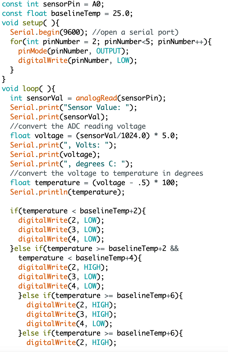
Here there is the full code just in case