Losi Remote Control Car Quick Charger Hack
by DualPhase in Circuits > Remote Control
6935 Views, 10 Favorites, 0 Comments
Losi Remote Control Car Quick Charger Hack
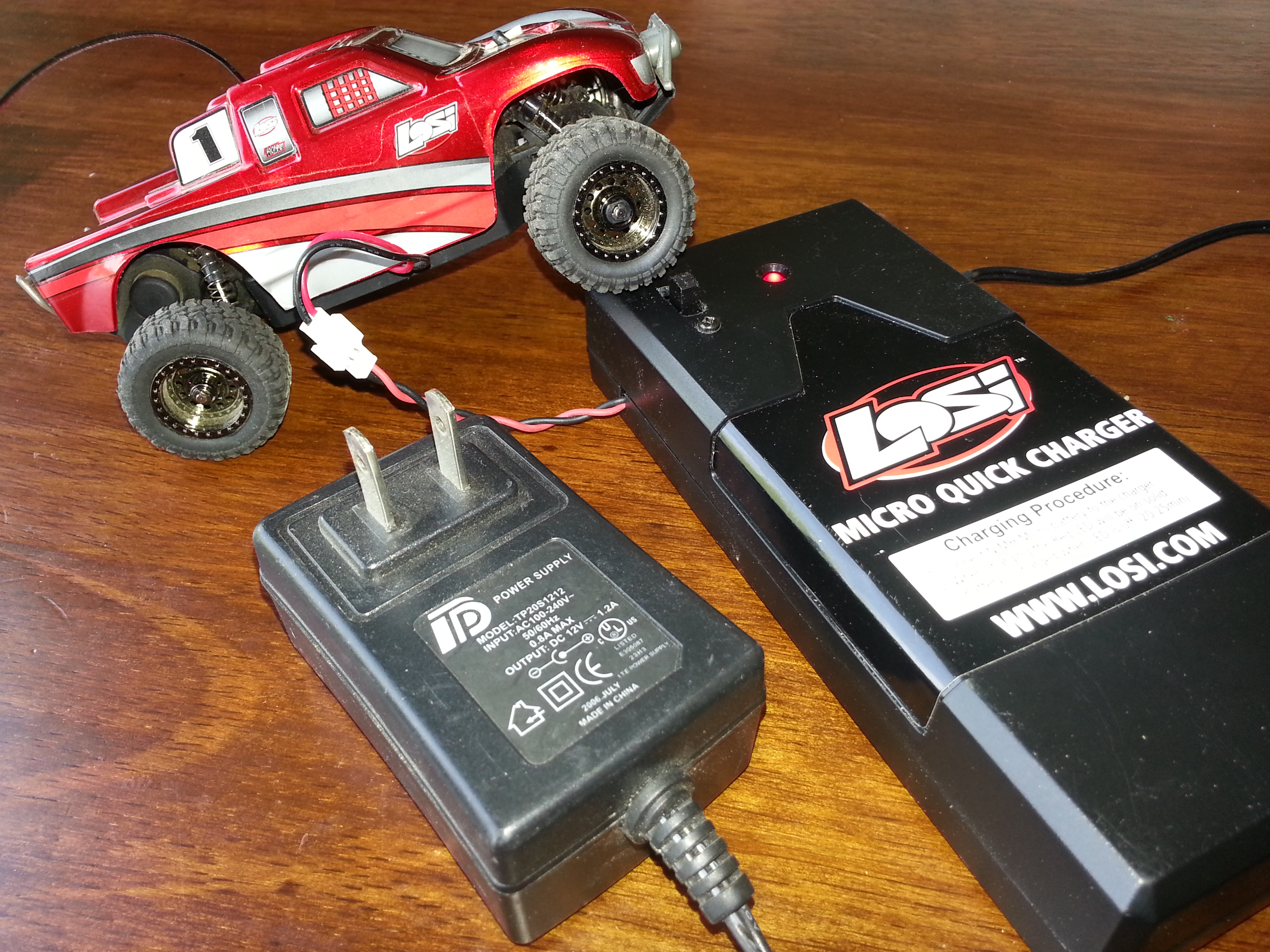
This instructable will outline the instructions for modifying a Losi Micro Quick Charger to accept sources from a Wall Adapter or Batteries
PROBLEM: The Losi RC car charger only allows the car battery to be charged by other batteries. Since the charger uses 8 AA batteries the cost of charging the car battery can be great.
SOLUTION: Adapt the charger to accept power from a wall outlet while retaining the ability to charge from the batteries when no outlet is available.
Parts and Tools Required
TOOLS
PARTS
- Solder Iron
- Knife or Wire Cutters
- Phillips Screwdriver
PARTS
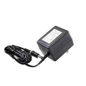
- 12V Wall Adapter (between 300mA - 800mA or more)
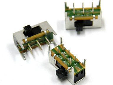
- Switch - 3 terminal posts(optional - If you want to switch sources)
Open and Identify Connection Points
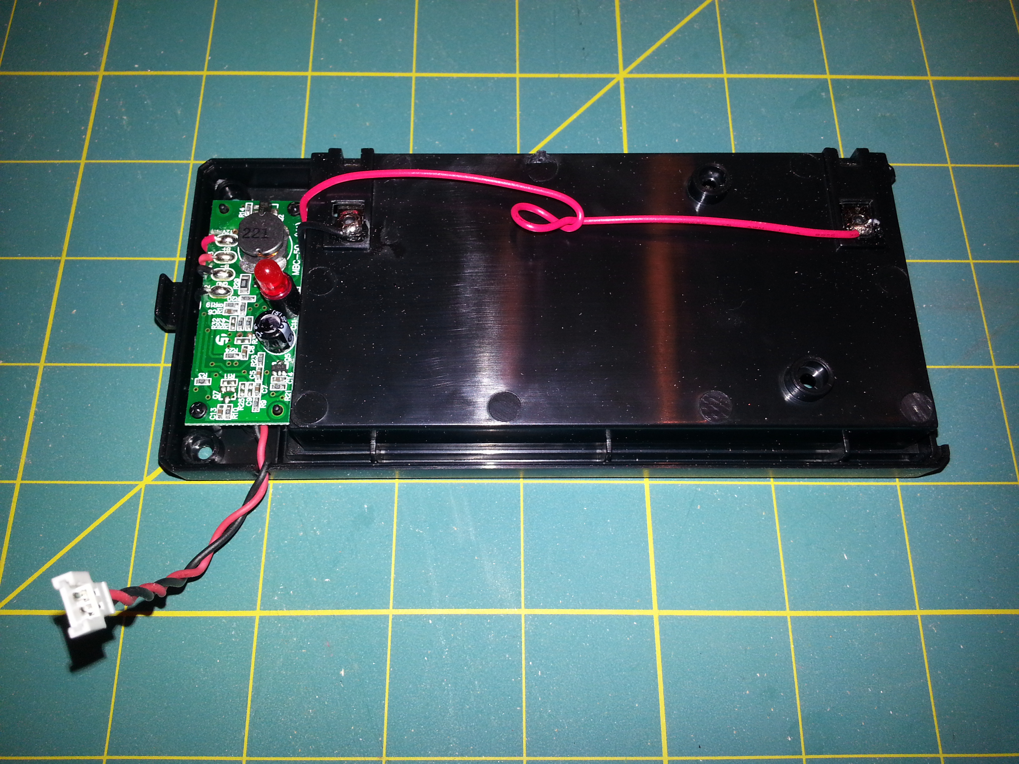
Remove the AA Batteries and open the charger by removing the small Philips screws located on the back.
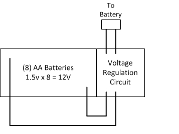
As you can see outlined by the simplified schematic the charger has three basic parts.
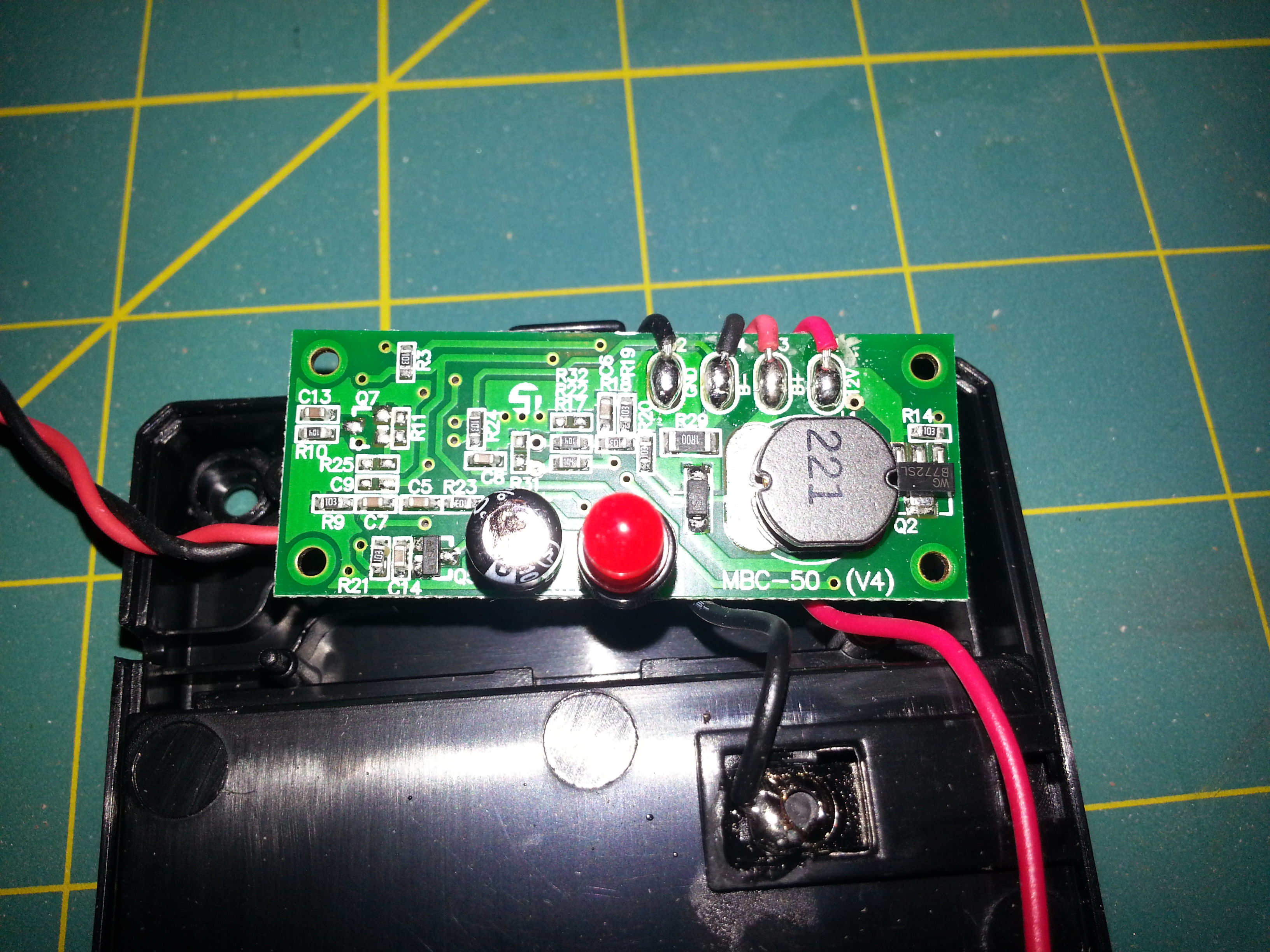
Identify the red and black wires connecting the batteries to the Voltage Regulation Circuit (green board). The red wire is the only wires that will need to be altered in this modification.
As you can see outlined by the simplified schematic the charger has three basic parts.
- Battery bank of 8 AA batteries
- Voltage Regulation Circuit (green board)
- Connector to Car Battery
Identify the red and black wires connecting the batteries to the Voltage Regulation Circuit (green board). The red wire is the only wires that will need to be altered in this modification.
Connect Wall Adapter and Switch
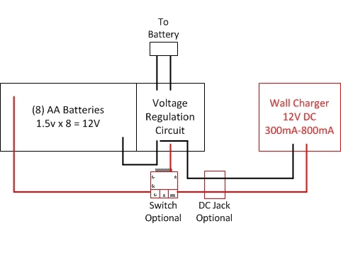
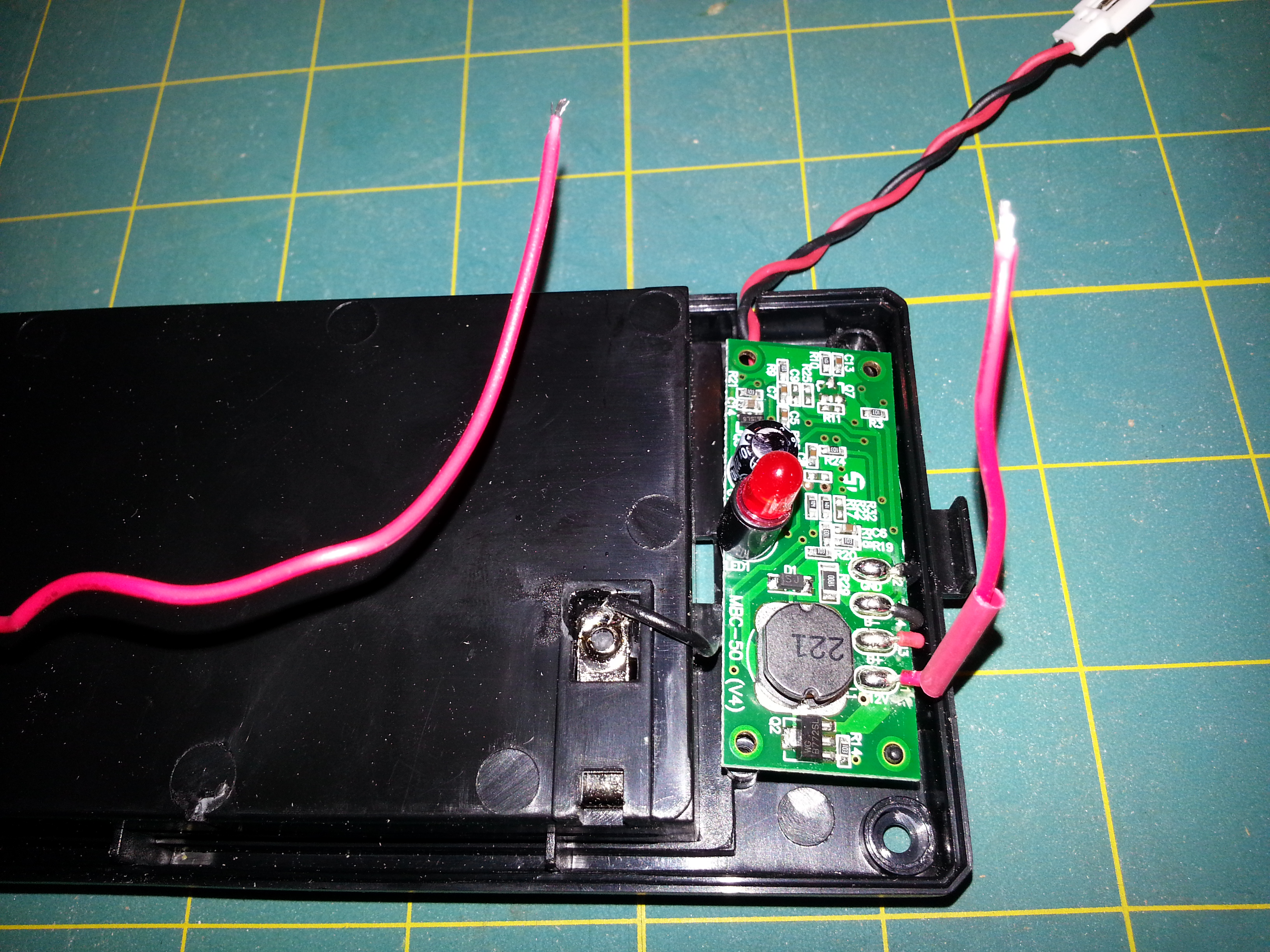
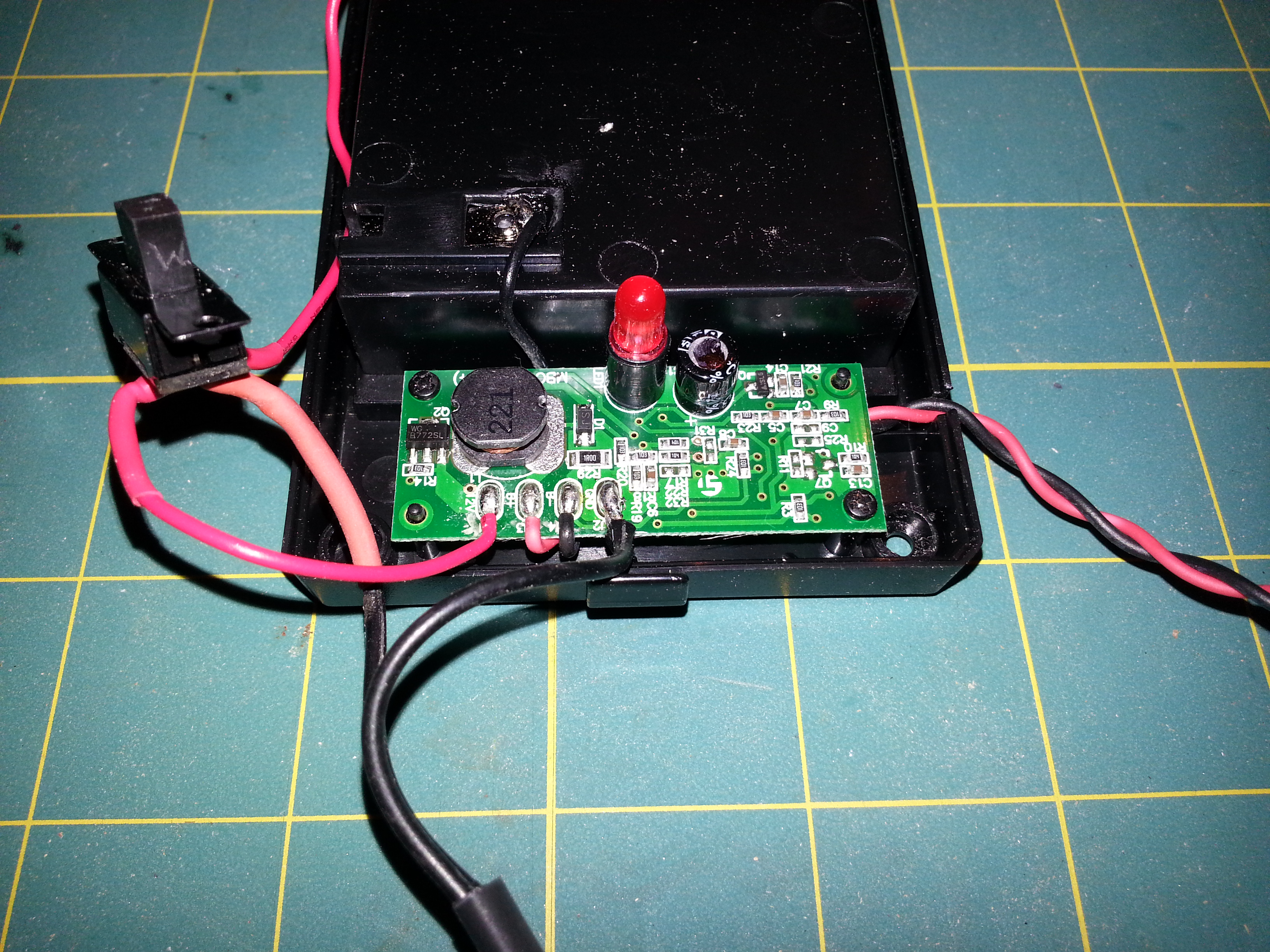
Just connect per the diagram or follow the steps:
- Cut red wire from Battery Bank to Voltage Regulation Circuit.
- Solder one end of red wire to switch (1st terminal)
- Solder other end of red wire to switch (2nd terminal)
- Cut off end of the 12V wall adapter
- Connect the positive end of the wall adapter to the switch (3rd terminal)
- Solder the negative end of the wall adapter to either end of the black wire that goes from the battery bank to the Voltage Regulation Circuit.
Cut Holes and Reassemble
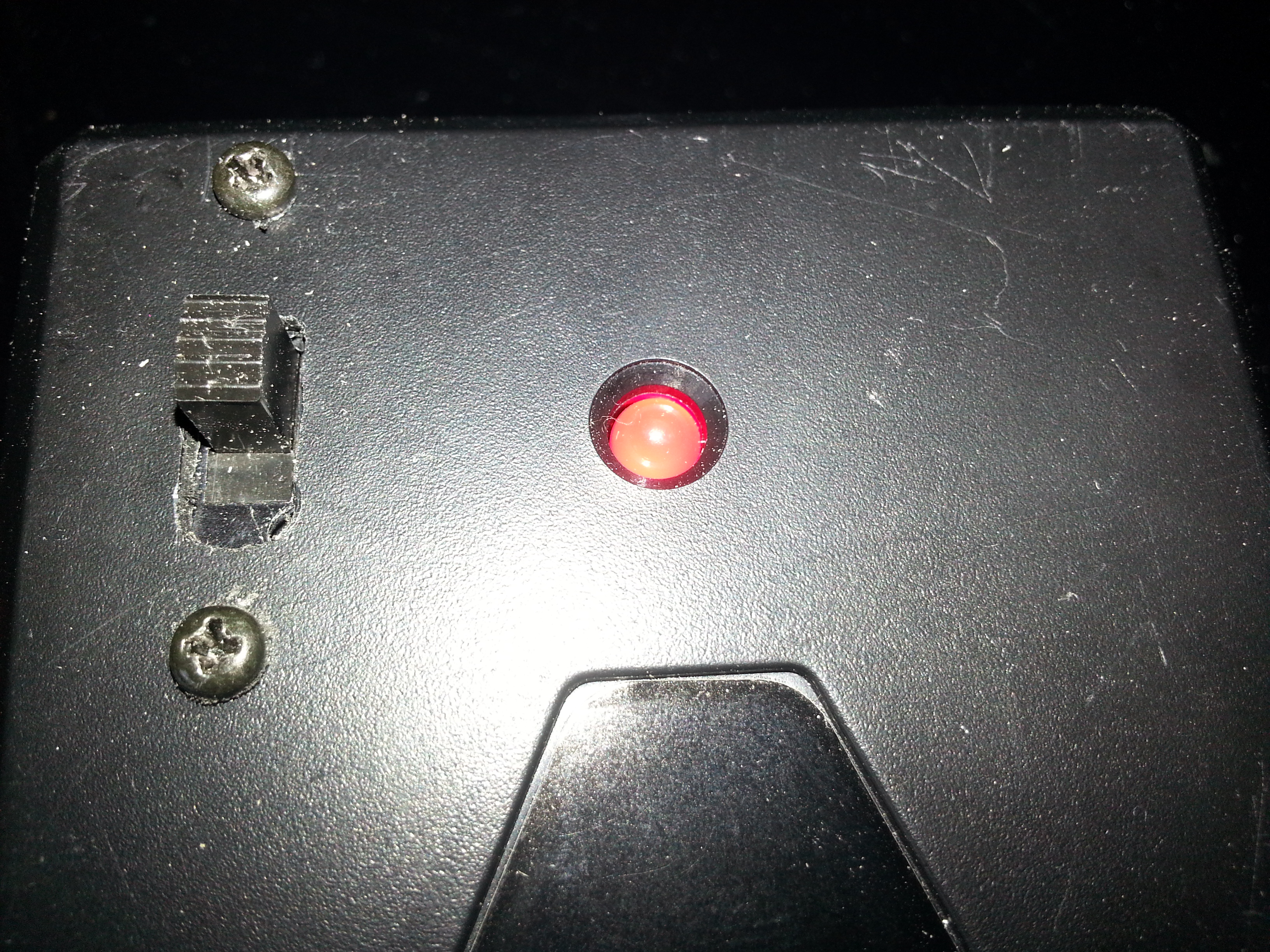
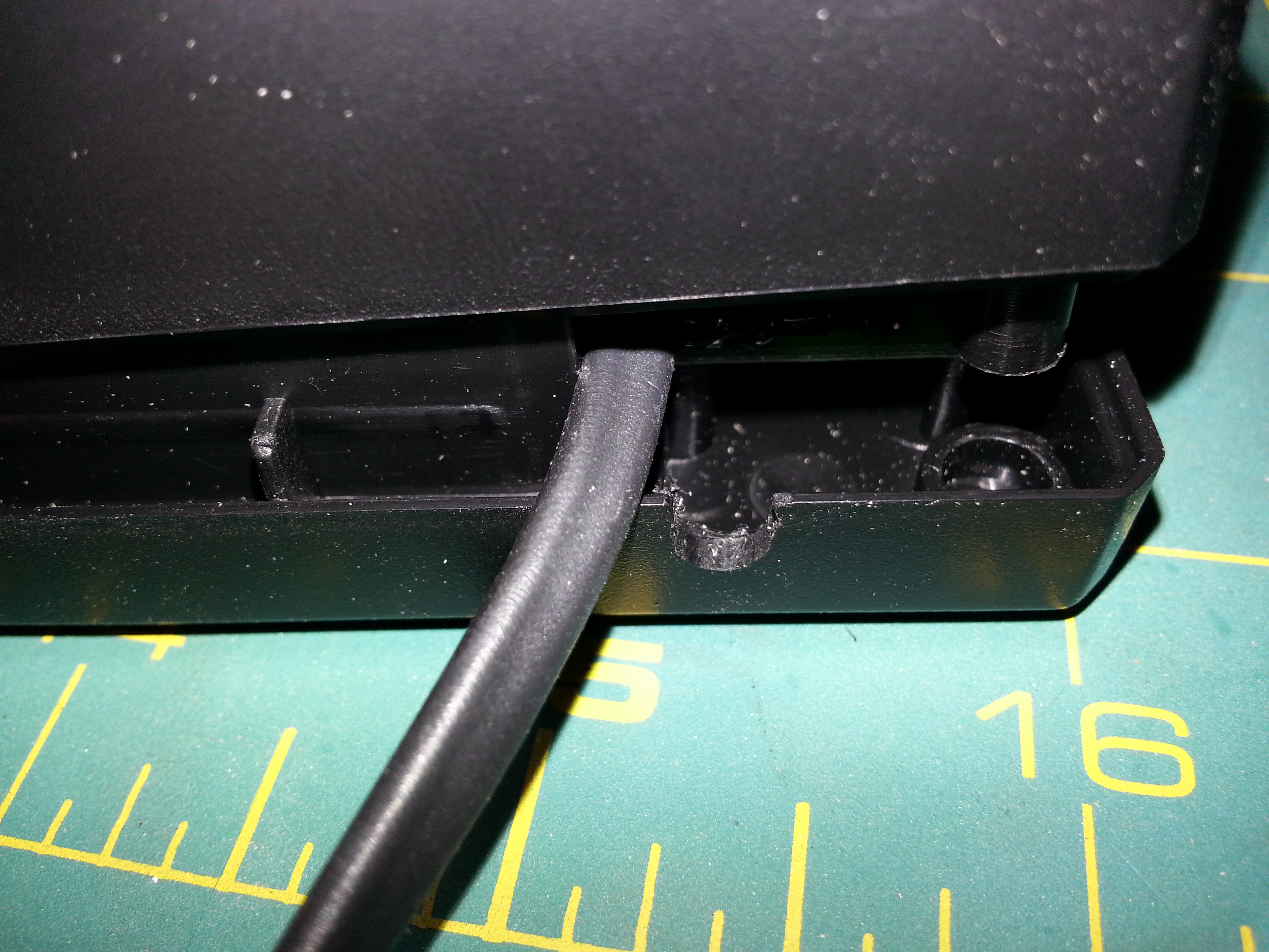
Cut two holes in the charger box for the switch and the wire to the wall adapter.
- Cut small hole for the wall adapter wire
- Cut hold for the switch and hold in place (hot glue, screws, compression)
- Screw back together
Test
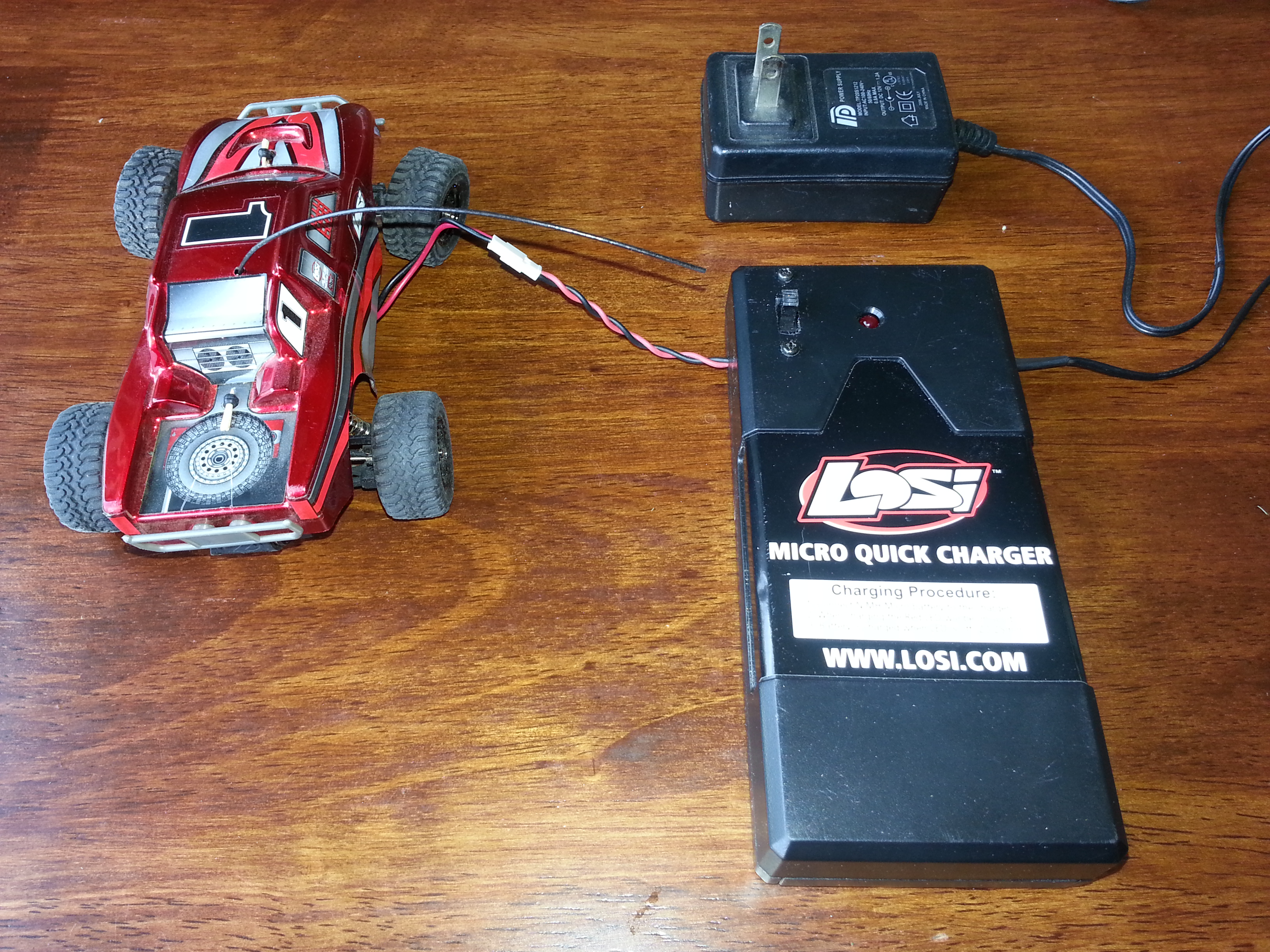
The charger should now charge the car battery from either source indicated by the position of the switch. You can label the switch position to correspond to batteries or wall charger. The LED will still operate indicating a charge.
- Optional: test output voltage of 3.7V on both possitions of the switch
- Connect the car battery and test that it charges the car battery on both positions of the switch