Load Cell
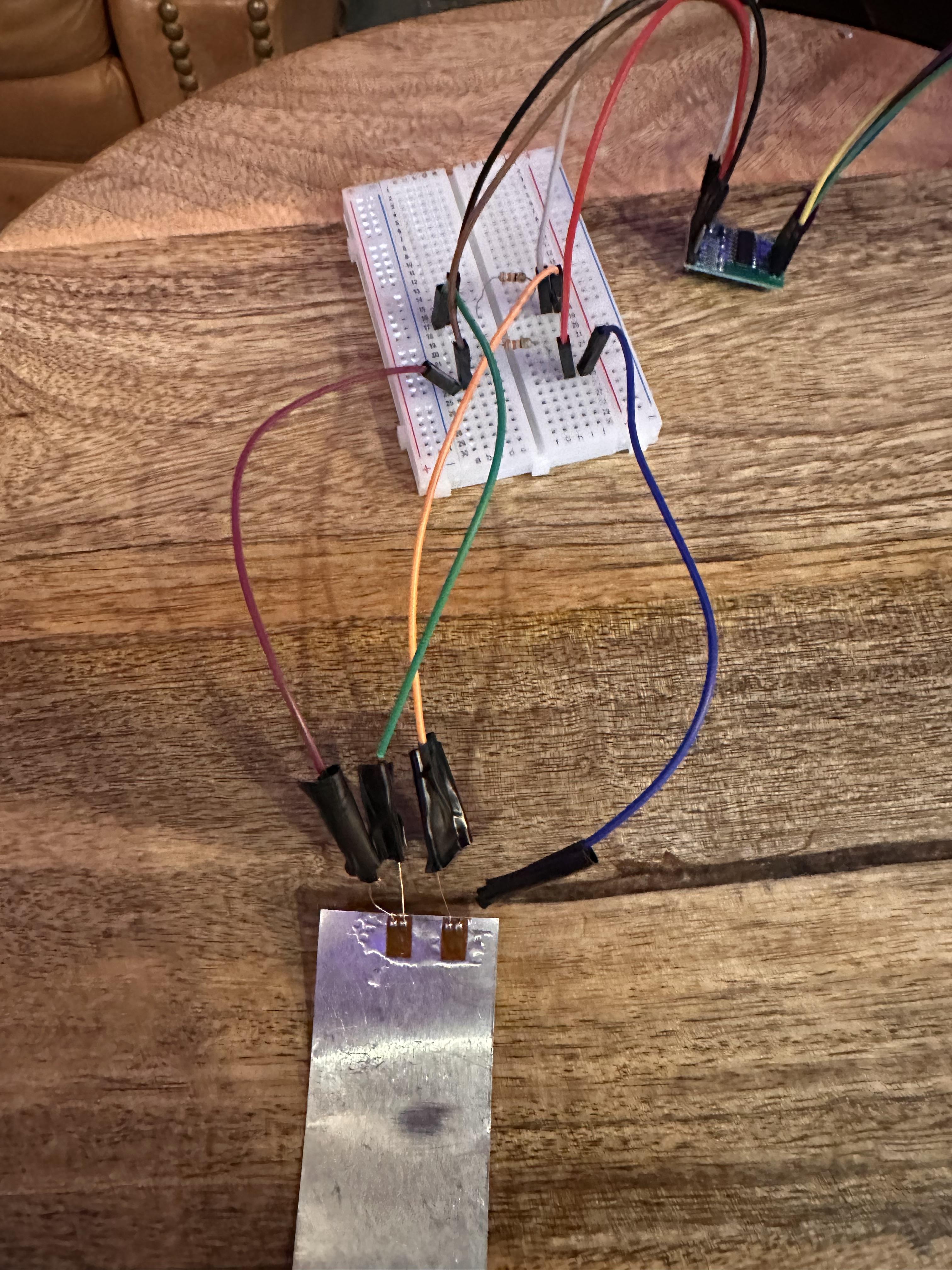
Build a strain-gage load cell out of basic electronic components.
Important Information
Strain Gage - Sensor used to measure strain (deformation) in an object. It works by converting the mechanical deformation of a material into a change in electrical resistance.
Wheatstone Bridge - An electrical circuit used to precisely measure strain from electrical resistance. It consists of four resistors in a diamond shape.
Supplies
- 1 - ESP32 microcontroller with USB cable.
- 1 - HX711
- 1 - Cyanoacrylate (CA) bonding adhesive or glue
- 1 - breadboard
- 2 - 320 ohm resistors
- 2 - 350 ohm strain-gages
- 8 - male-to-female wires
- 4 - female-to-female wires
ESP32 Microcontroller
- Download the latest version of Arduino IDE (https://www.arduino.cc/en/software)
- Download the drivers related to the hardware
- CP2102 driver
- Esp32 Board by Expressif Systems
- HX711 Arduino Library
- Plug your arduino into your computer and test the connection.
- After plugging in, open Arduino IDE app and select your board: DOIT ESP32 DEVKIT V1
- Under File, hover over ‘Examples’, then ‘01.Basics’, and click Blink and run it.
Wiring & Strain-gage
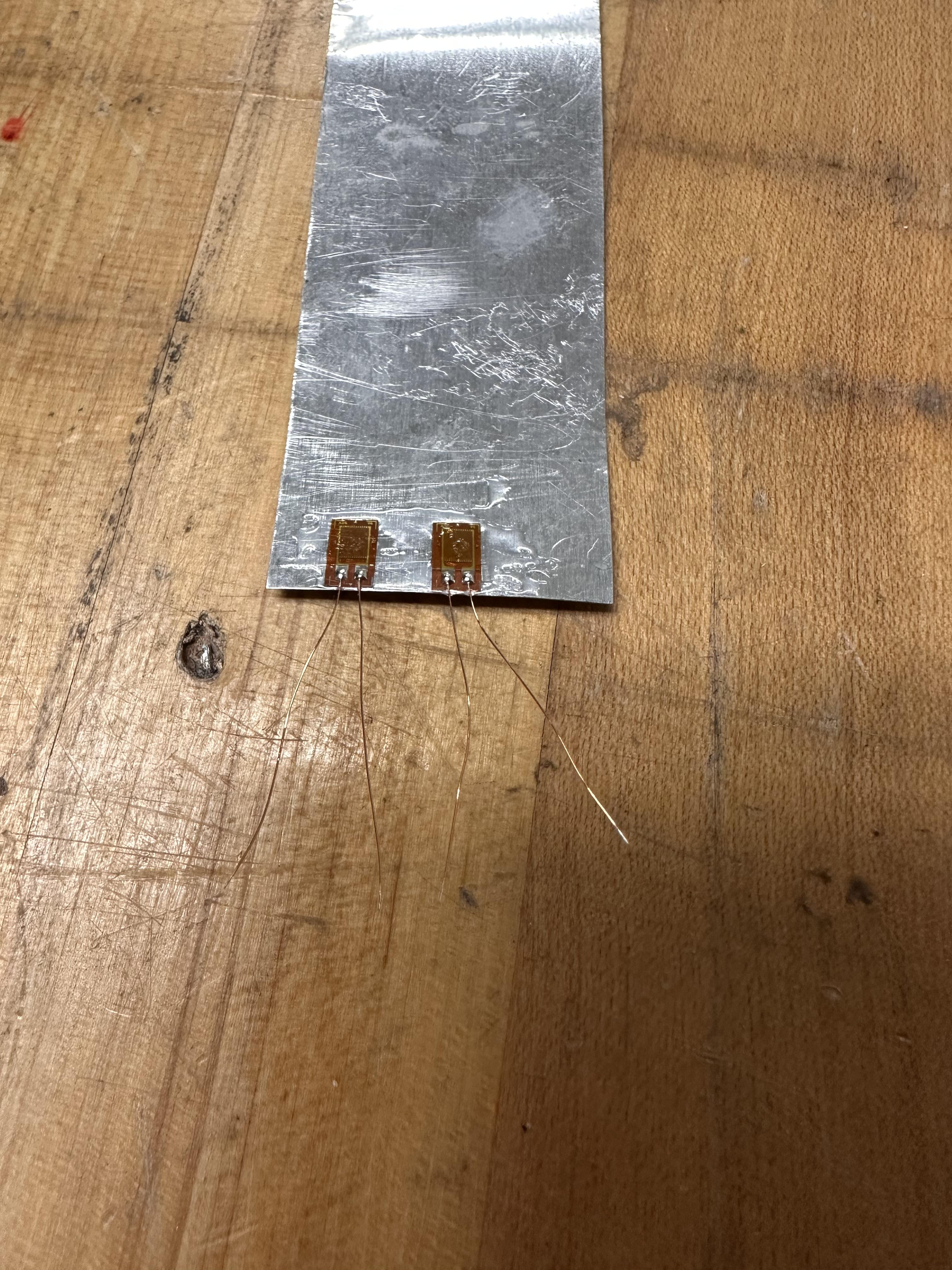
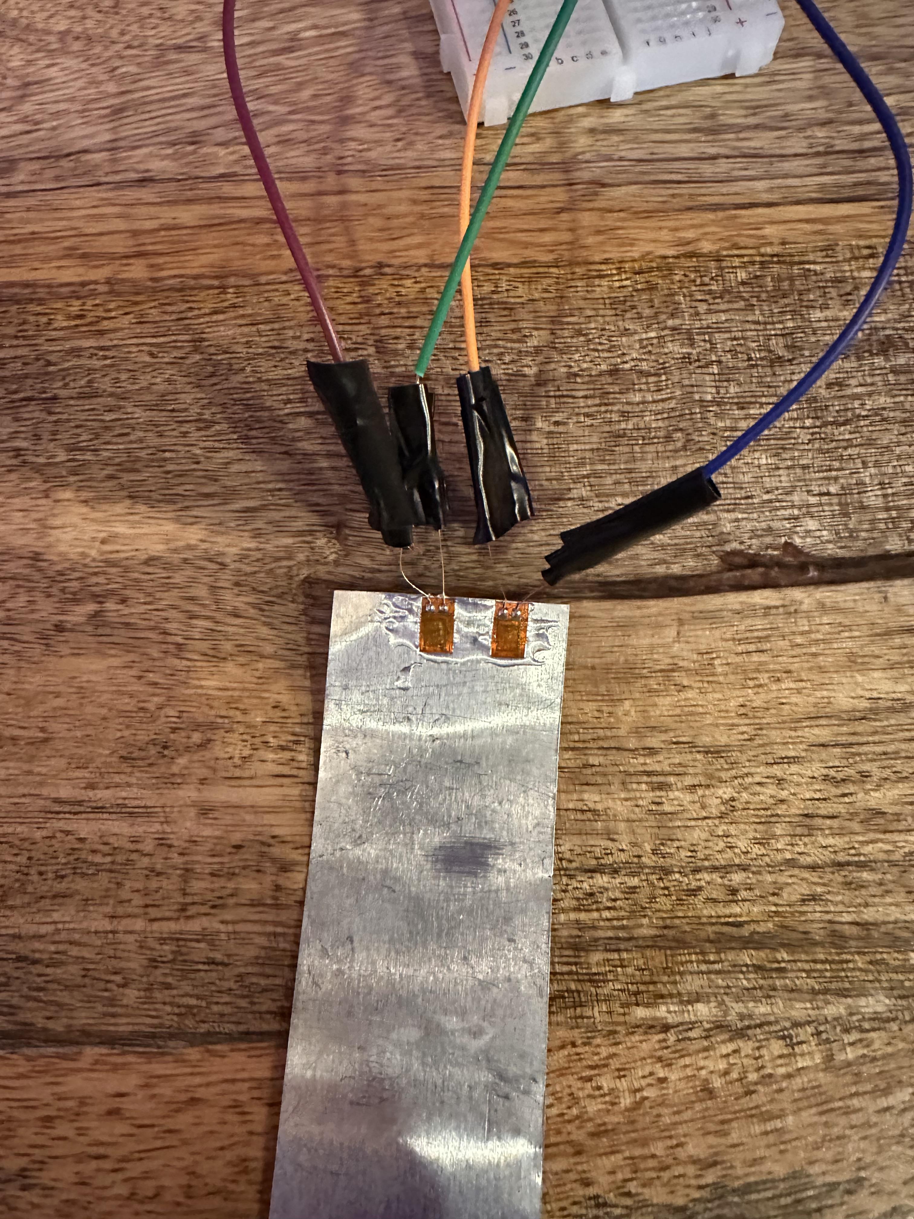
- Using glue, attach the 2 strain-gages to the surface you are testing.
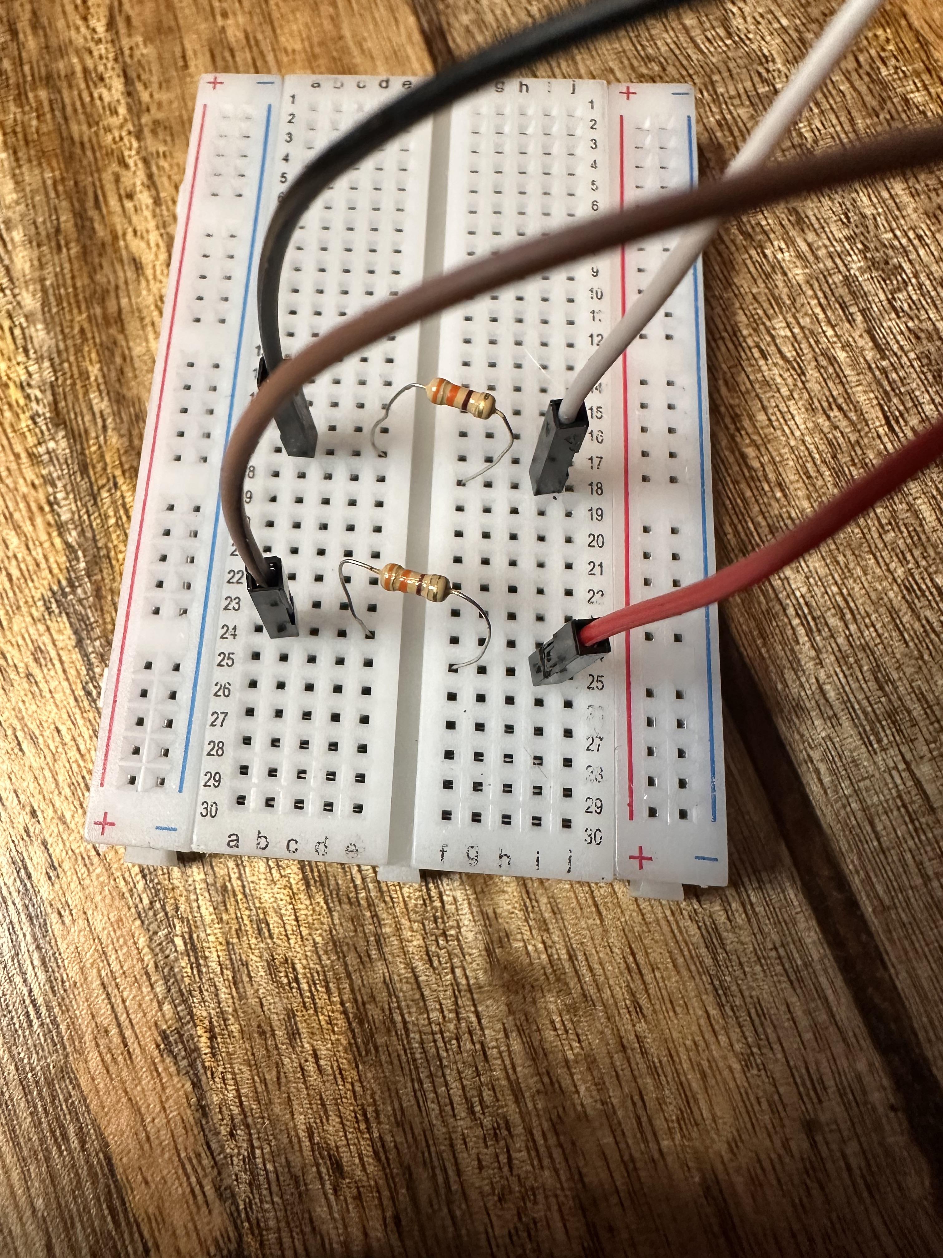
- Set up your bread board and plug 4 male end wires into it (17a, 24a, 18j, 25j).
- For the male end wires, depending on which you’re using, you may need to wire strip the ends that will connect to the strain-gage. Solder the bare ends of wire to the strain-gage wires, 17a/18j to the two inside wires and 24a/25j to the two outside wires (see image).
- Place the two resistors in between the wires (17e/18f, 24e/25f).
- Wire the HX711 and ESP32 using 4 female-to-female wires:
- D21 of ESP32 to DT of HX711
- D22 of ESP32 to SCK of HX711
- VIN of ESP32 to VCC of HX711
- GND of ESP32 to GND of HX711
- Wire the HX711 to the strain-gage wiring on the breadboard using 4 male-to-female wires
- On HX711, E+/E- and A-/A+ will be pairs that are place on opposite corners
- Example: E+ -> 18i, E- -> 24b, A- -> 25i, A+ -> 17b
- Note: They need to be on opposite corners and inside of the strain-gage wiring.
Run Code
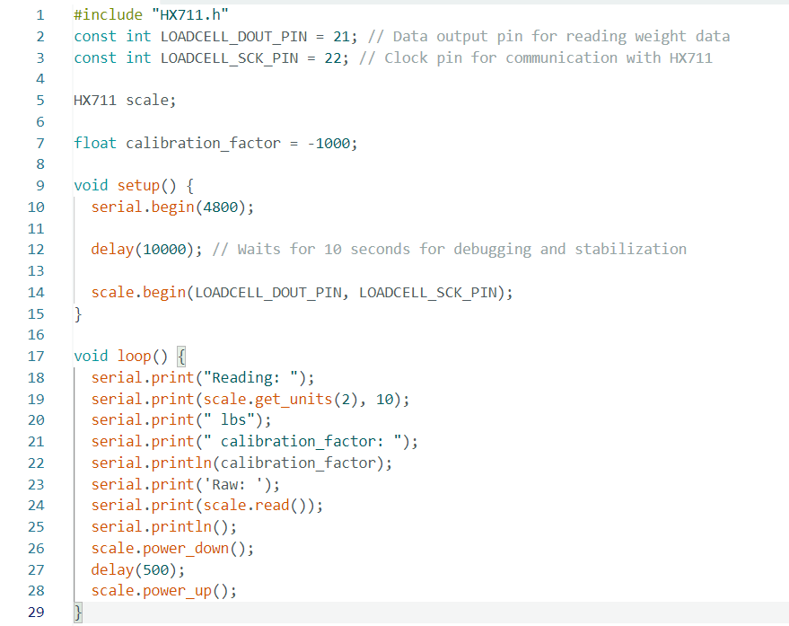
- Run code below
- Go to tools, click Serial Monitor (ctrl + shift + m), set the baud to 4800 and view results.
#include "HX711.h"
const int LOADCELL_DOUT_PIN = 21; // Data output pin for reading weight data
const int LOADCELL_SCK_PIN = 22; // Clock pin for communication with HX711
HX711 scale;
float calibration_factor = -1000;
void setup() {
serial.begin(4800);
delay(10000); // Waits for 10 seconds for debugging and stabilization
scale.begin(LOADCELL_DOUT_PIN, LOADCELL_SCK_PIN);
}
void loop() {
serial.print("Reading: ");
serial.print(scale.get_units(2), 10);
serial.print(" lbs");
serial.print(" calibration_factor: ");
serial.println(calibration_factor);
serial.print('Raw: ');
serial.print(scale.read());
serial.println();
scale.power_down();
delay(500);
scale.power_up();
}