LinkIt One Voltage Montior
by appytechie in Circuits > Microcontrollers
708 Views, 4 Favorites, 0 Comments
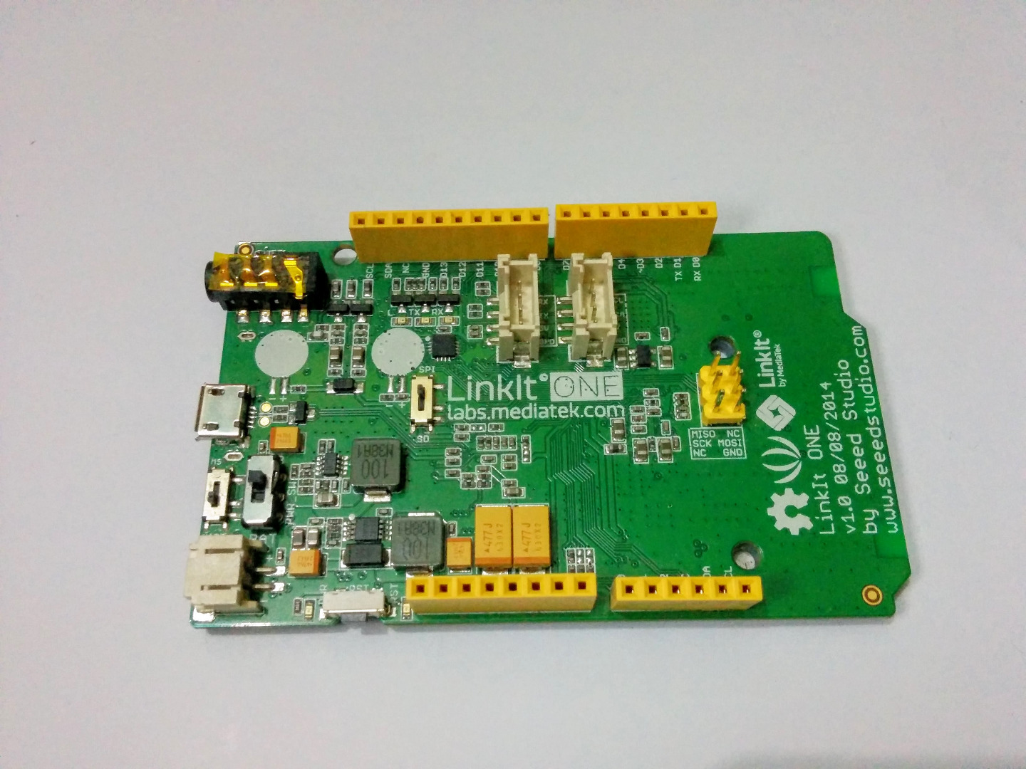
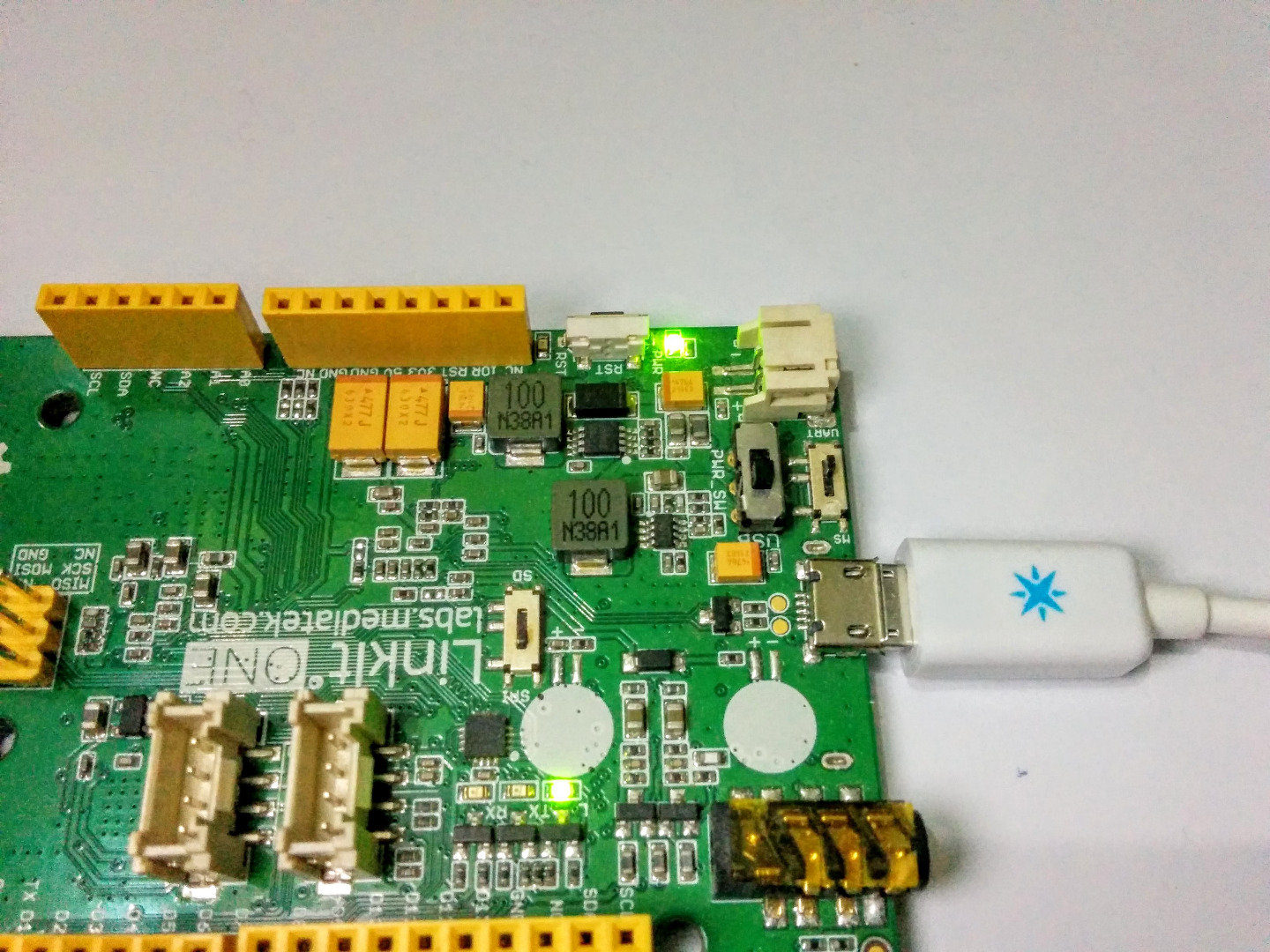
LinkIt One Voltage Montior


While working with IoT and wearable tech we have to keep track of the battery Levels to keep the circuit working. Luckily the LinkIt one has a inbuilt feature that would display the voltage level of the battery provided with the LinkIt One board. And In today's project I'm going to show you how to measure the voltage of both the internal battery or an external battery if you are powering it from an external battery. This project would be able to read voltages of up to 30V and give you control over the circuit if the battery goes low or how much of the battery you have left.
Tools and Components


So lets start with gathering all the components and tools required for
this project. Most of the components come along the LinkIt one box, like battery and WiFi antenna. So here is what you need -
- LinkIt One
- Grove Voltage Divider
- BreadBoard
- Jumper wires
- Battery (Included in the LinkIt One box)
Circuit

There is no circuit required if you are using the battery provided in the LinkIt One box. But if you are going the extra mile or making a more complex project and you want to know the voltage levels so you can control circuits respectively. Here is how the connections go
- Grove Voltage Divider VCC - LinkIt One +5V
- Grove Voltage Divider Gnd - LinkIt One GND
- Grove Voltage Divider Sig - LinkIt One Analog pin 0
Code - Linkit One Battery


The code for the battery that came with the Linkit One battery can be found below, you require the Arduino IDE with the LinkIt One plugin to upload the code to the board also make sure you select the right port while uploading the code to the board.
#include

char buff[256];

void setup() {
  // put your setup code here, to run once:
  Serial.begin(115200);
}

void loop() {
  // put your main code here, to run repeatedly:
  sprintf(buff,"battery level = %d", LBattery.level() );
  Serial.println(buff);
  sprintf(buff,"is charging = %d",LBattery.isCharging() );
  Serial.println(buff);
 delay(1000);
}
Code - Voltage Divider

The code for the voltage divider can be found below, by setting the gain switch to 3 you can measure voltages up to 14V and by setting the gain to 10 you can measure voltages up to 30v. You can measure the values of voltages from any analog pin and the LinkIt One board has 6 analog pins. By default the program is set to display the voltage readings over a serial terminal.
void setup(){<br>  Serial.begin(9600);
}

void loop(){
   long  sensorValue=analogRead(A0);
   long  sum=0;
   for(int i=0;i<1000;i++)
   {
      sum=sensorValue+sum;
      sensorValue=analogRead(A0);
      delay(2);
   }
   sum=sum/1000;

   Serial.print("if you set the Gain to 10,the input voltage:");
   Serial.println(10*sum*4980/1023.00);

   Serial.print("if you set the Gain to 3,the input voltage:");
   Serial.println(3*sum*4980/1023.00);

   delay(1000);
}