LinkIt One IR Detector
by robo10302 in Circuits > Microcontrollers
2381 Views, 41 Favorites, 0 Comments
LinkIt One IR Detector
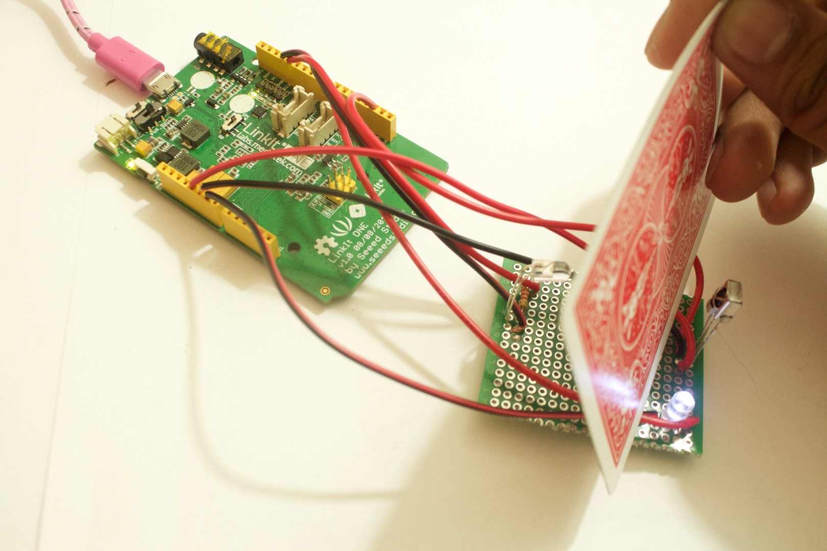
Hello Builders! Here in this project you will learn to make a IR breaker circuit. This means that the LED will light up once there is an object detected in between the IR sensor and the led. This project is made with a Microcontroller called the LinkIt One Board. The IR receiver is a 38khz IR sensor. In order to detect an object in between the signal being read from the sensor has to change from a 0 to a 1 meaning that it is no longer receiving the IR LED's output.
Parts
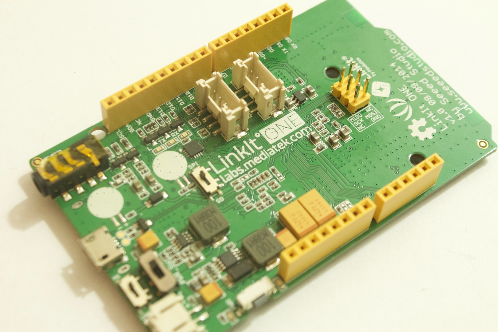
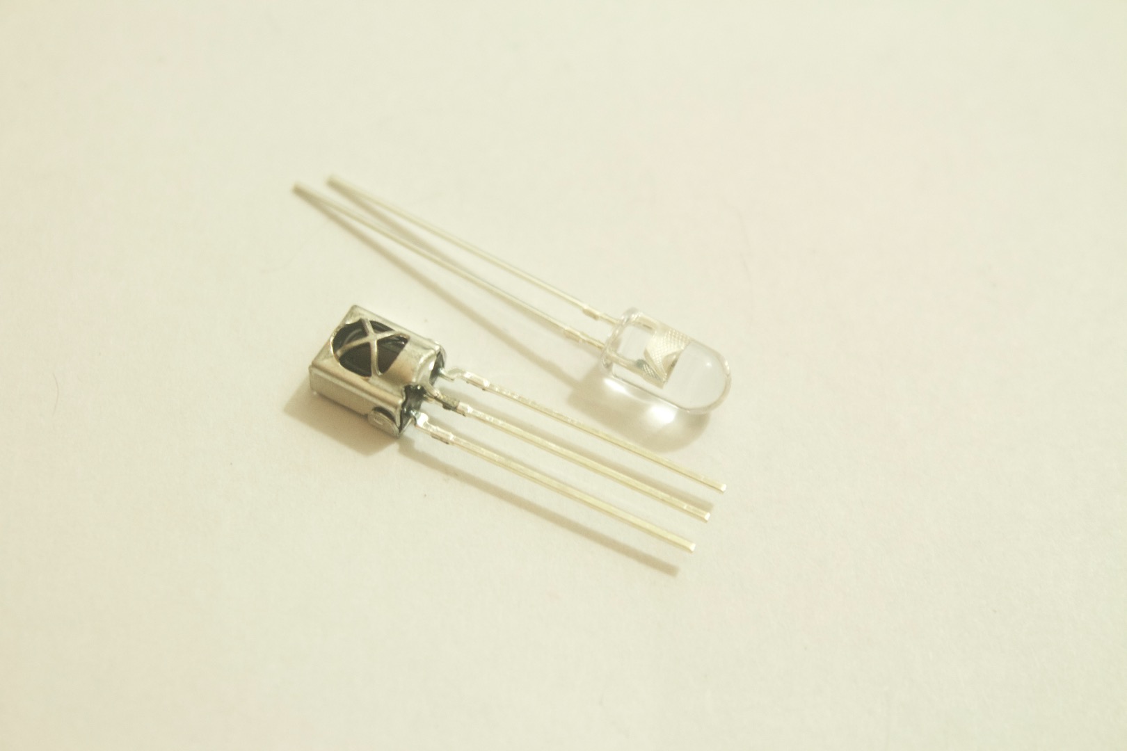
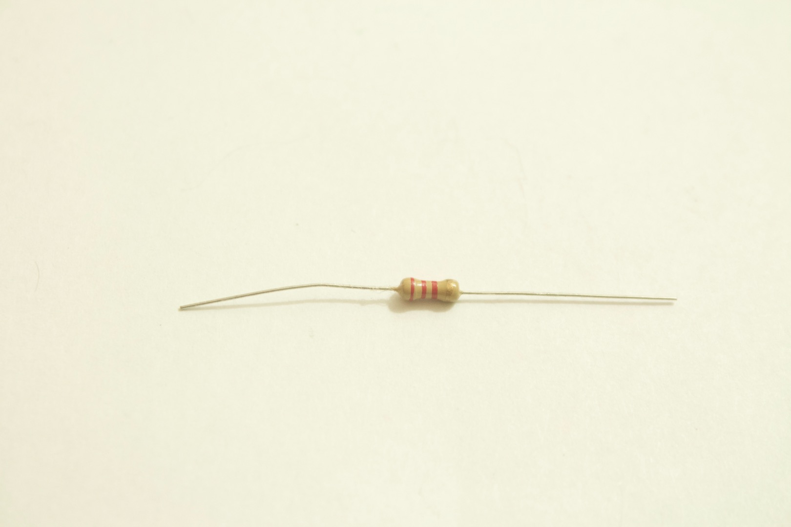
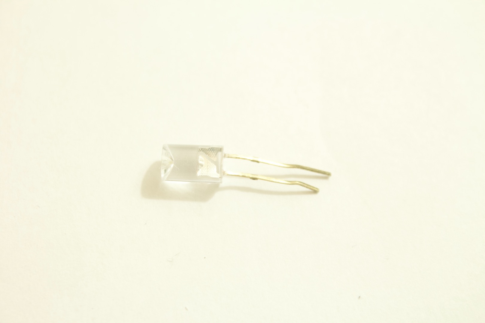
1. LinkIt One Board
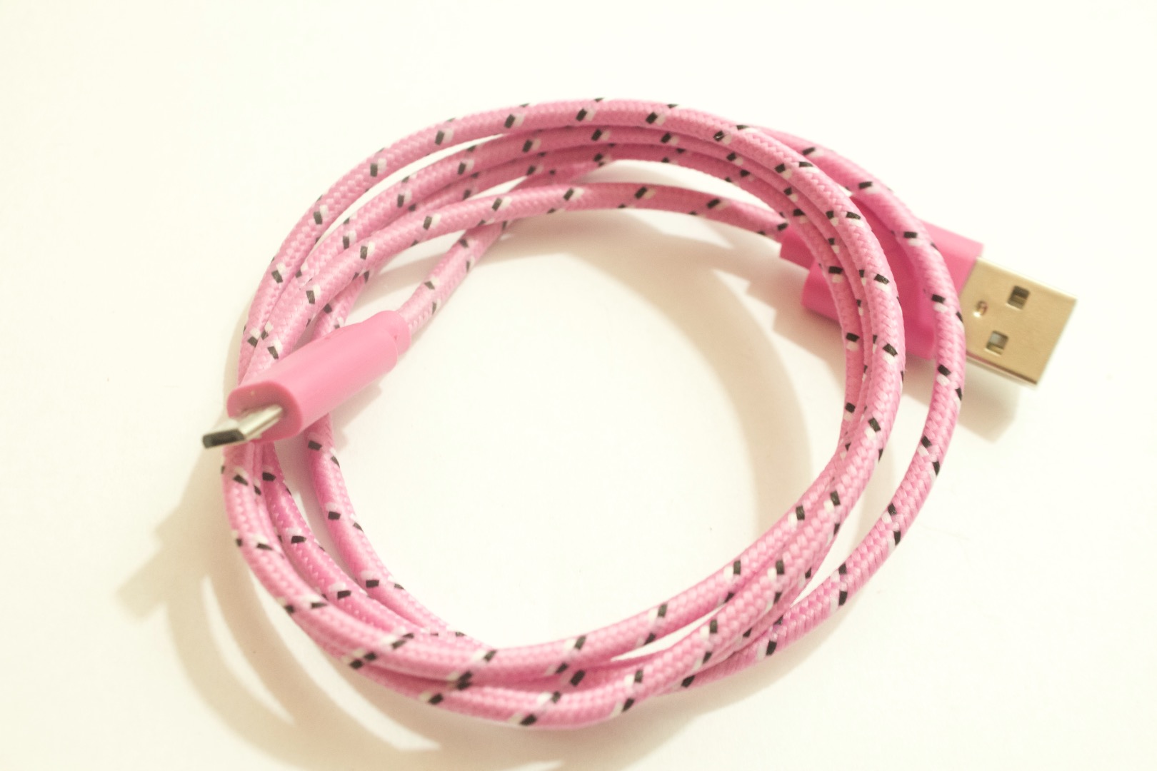
2. Usb Cable
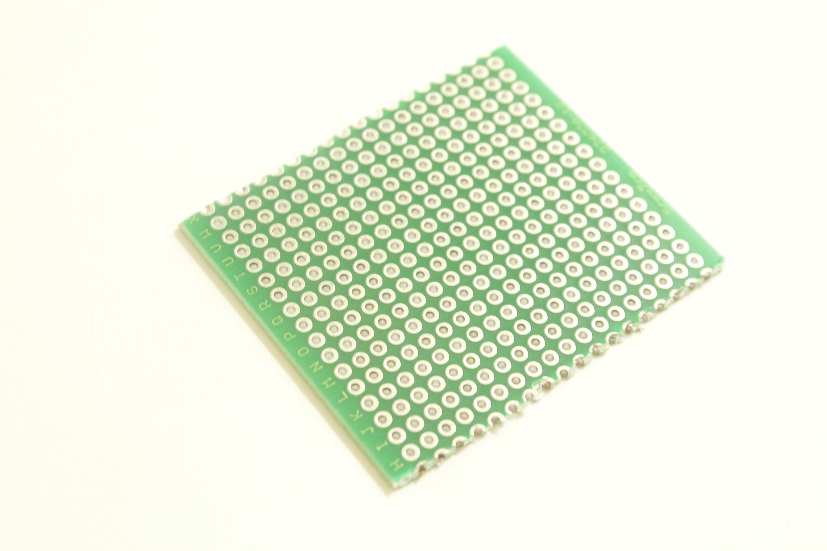
3. Perf Board
4. 38KHZ IR receiver
5. IR led
6. 330ohm resistor
7. LED( any color)
Solder the Circuit Board
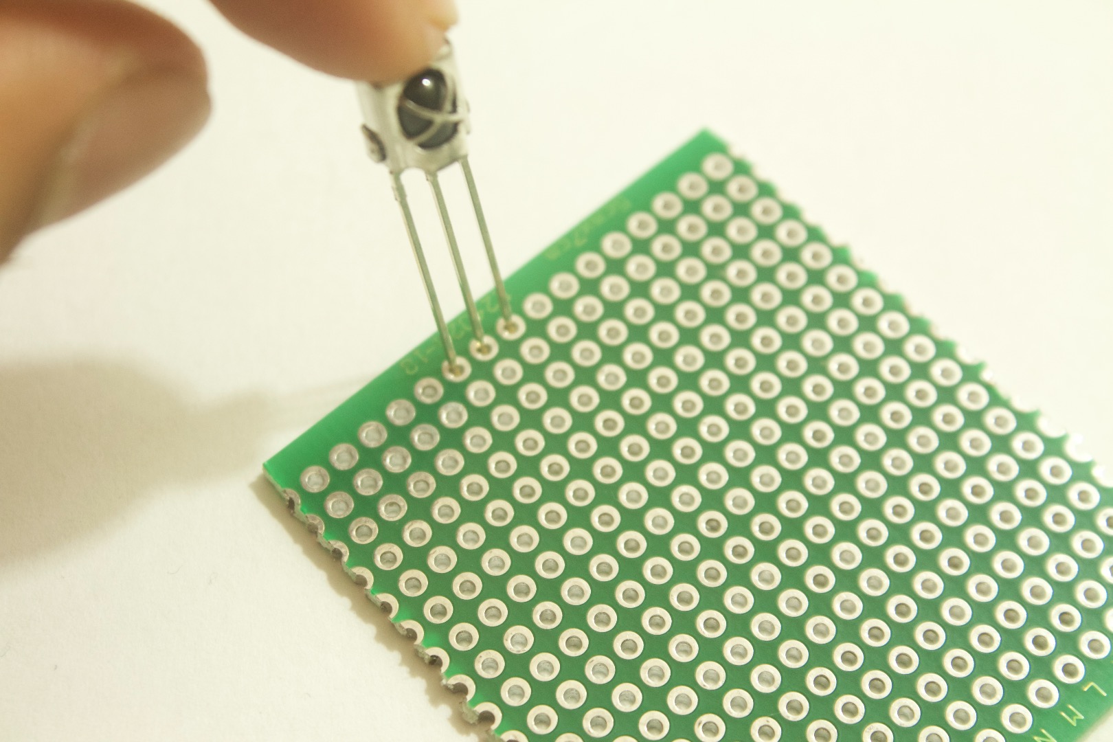
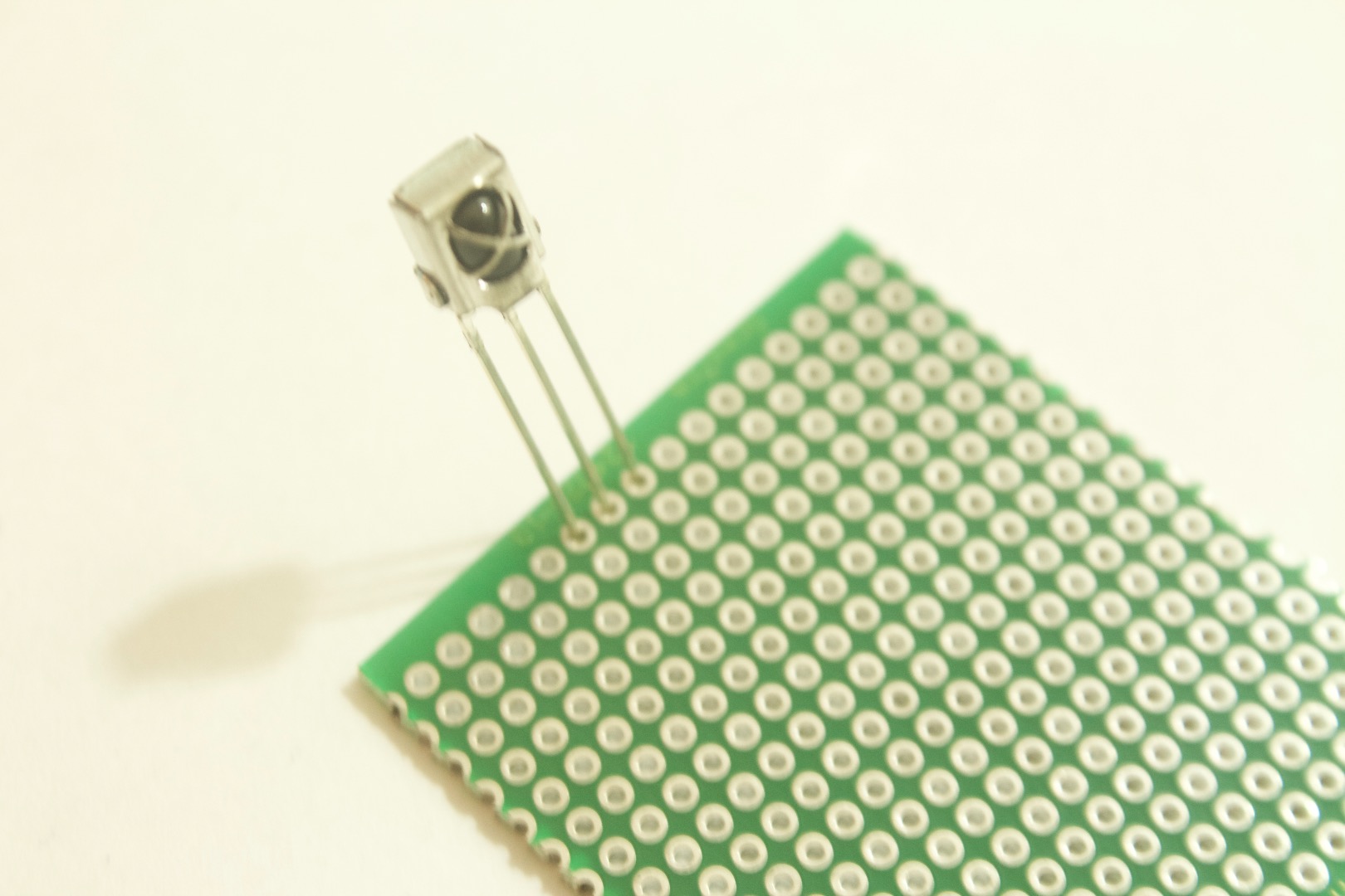
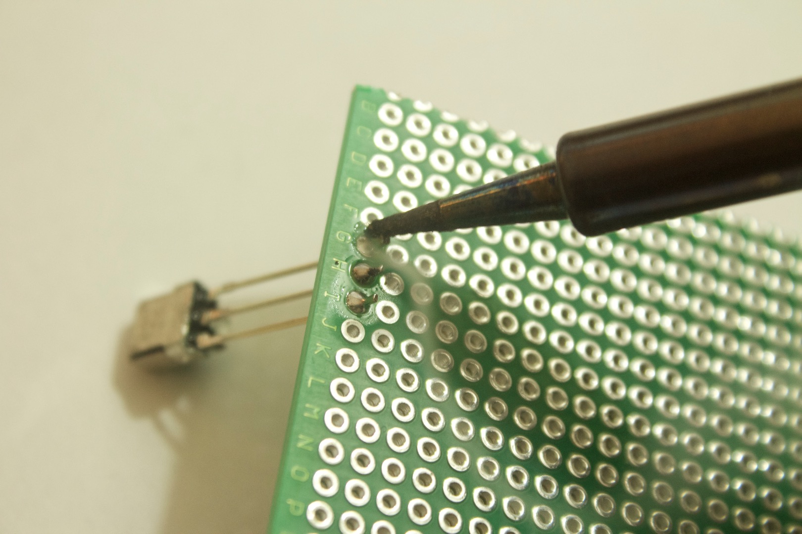
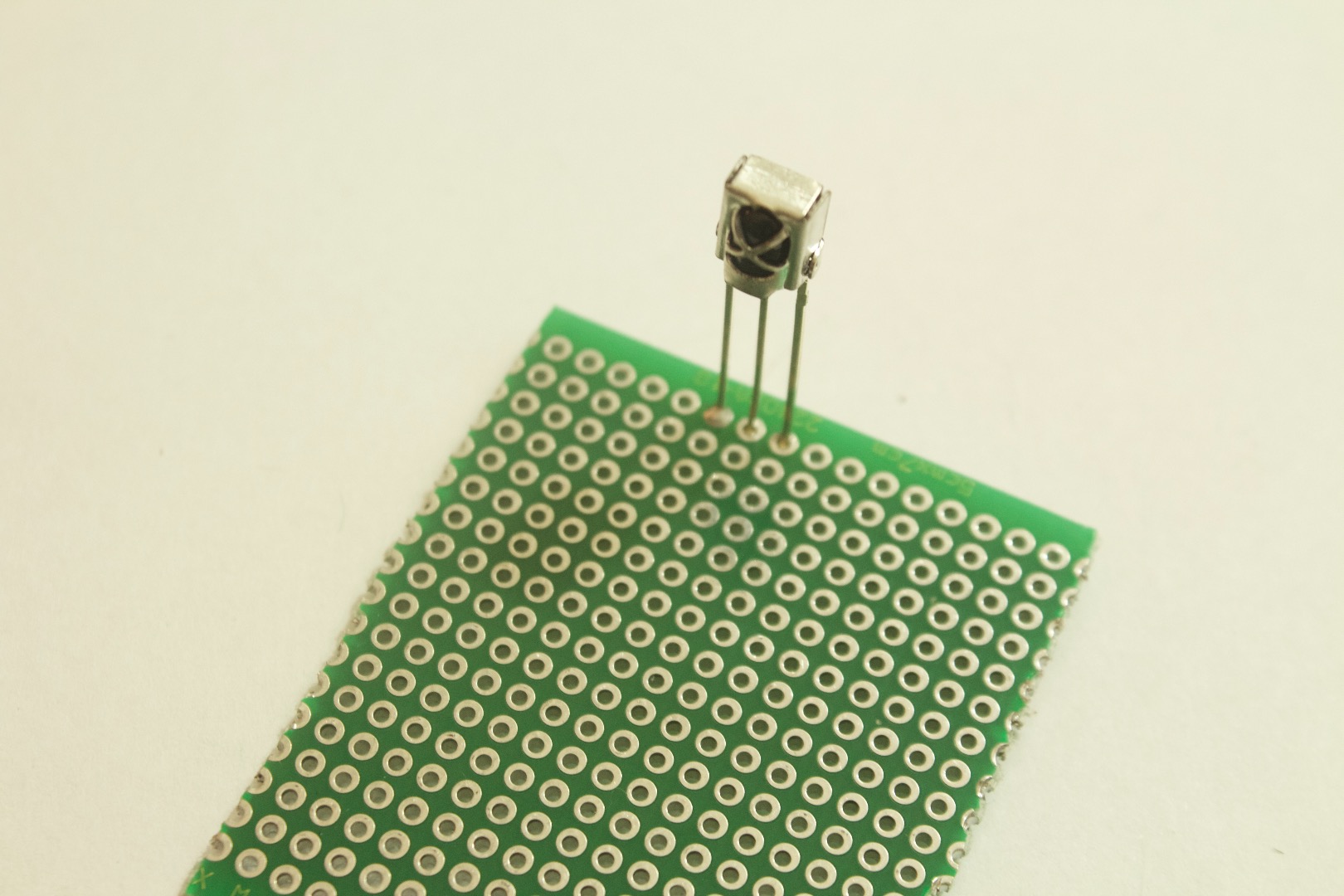
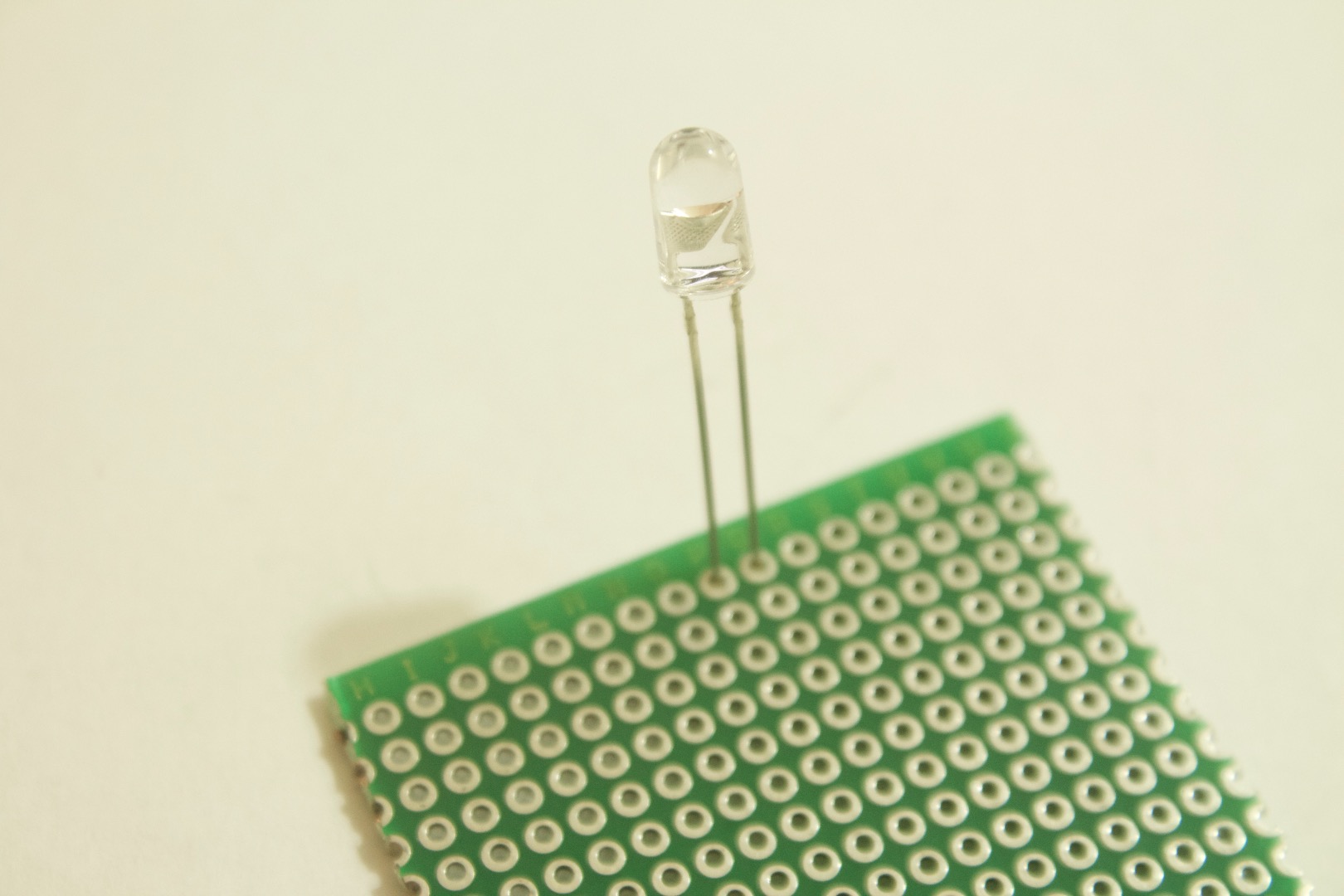
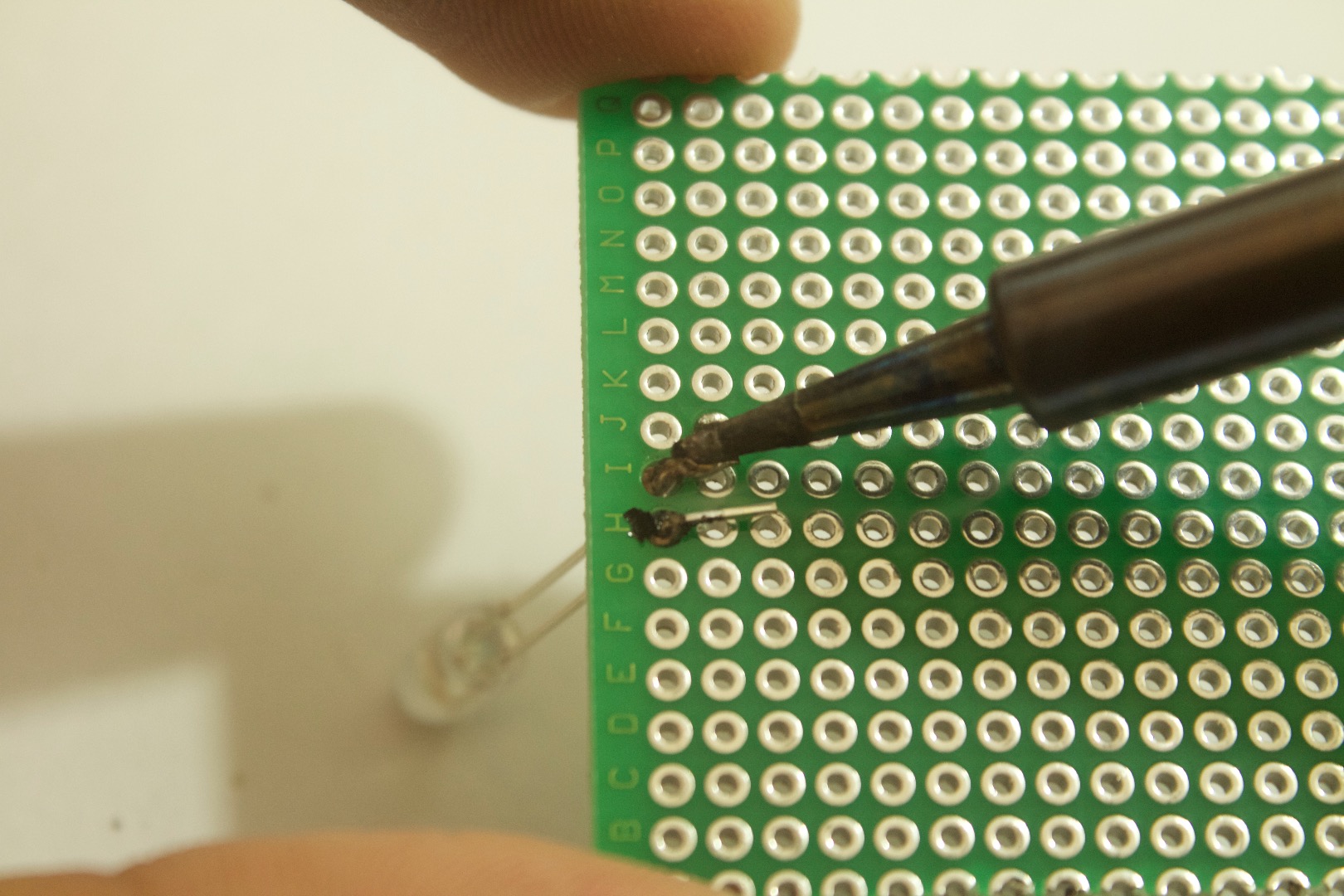
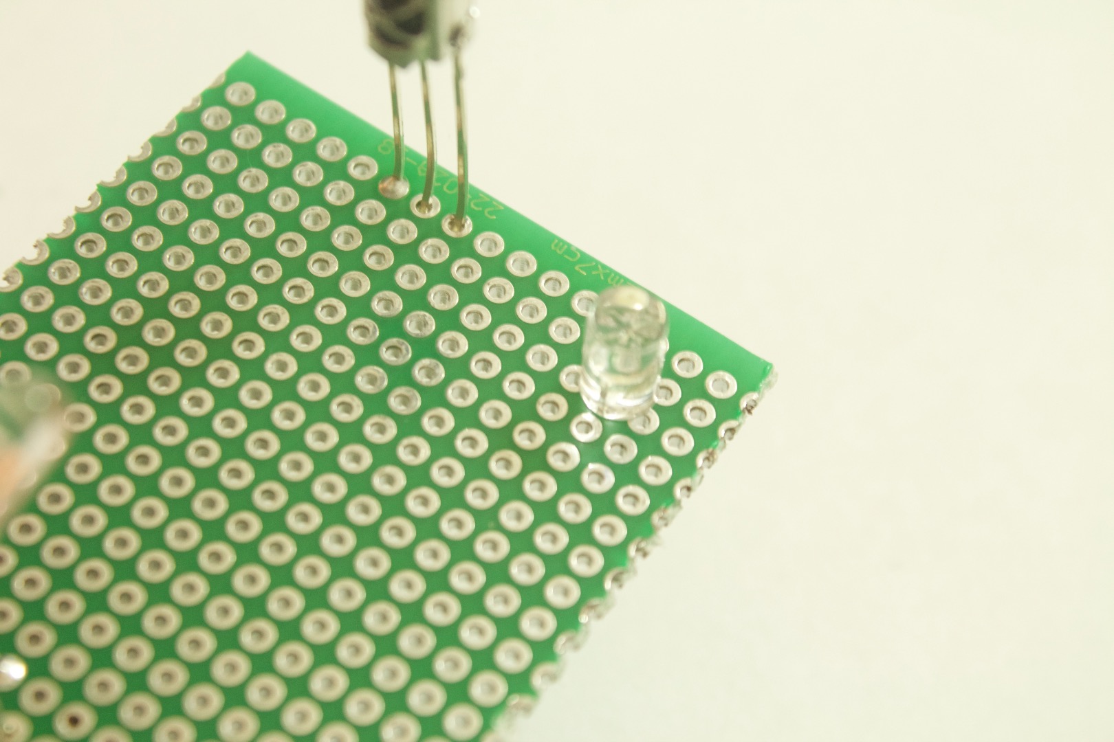
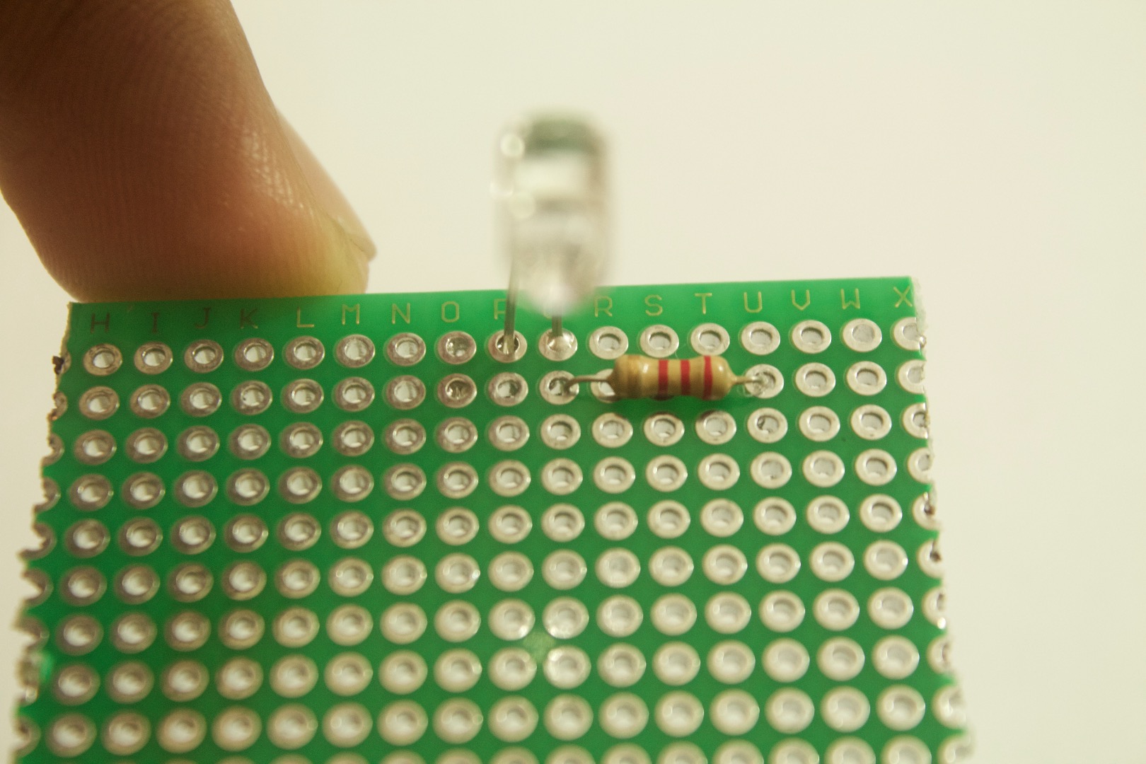
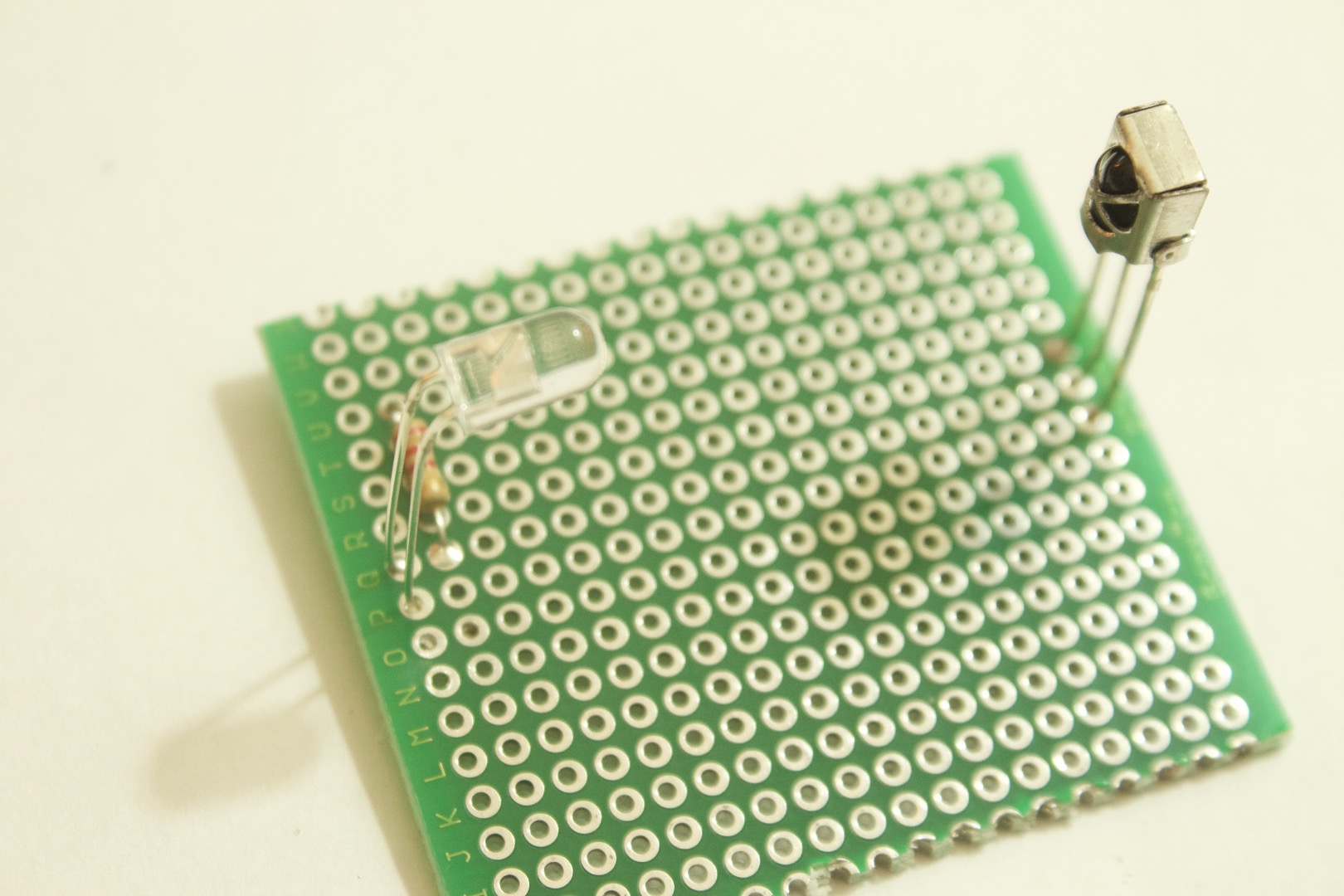
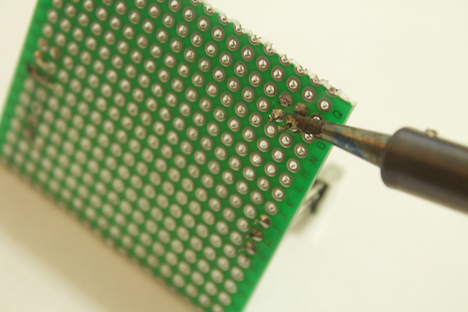
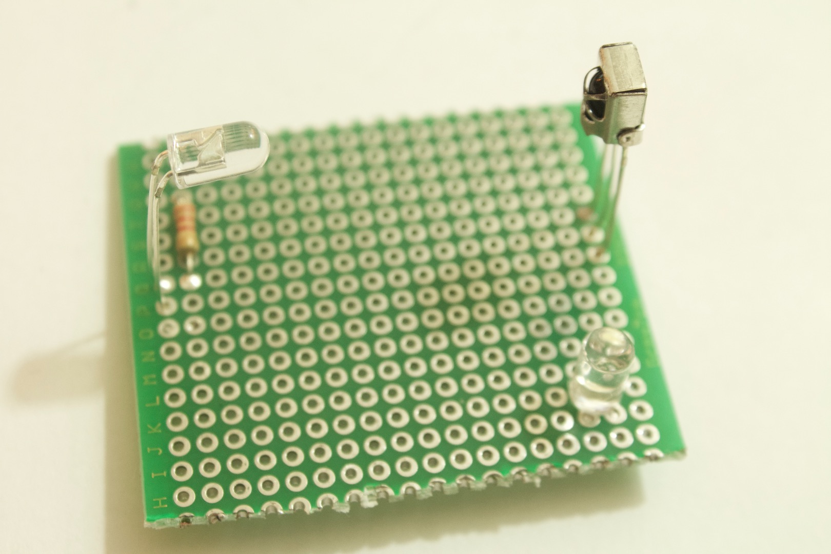
1. Start with soldering the IR sensor on the edge of the perf board.
2. Then at the exact opposite side solder the IR LED in such that it points towards the IR sensor.( the greater the distance between them the more space you get to detect the object)
3. Solder the resistor to the IR LED's positive pin.
4. Insert the normal led out of the way of the free space between the sensor and IR Led.
5. Solder the LED.
Make sure you have something that looks like the photo above and then you are ready to move on to soldering the wires.
Solder the Wires
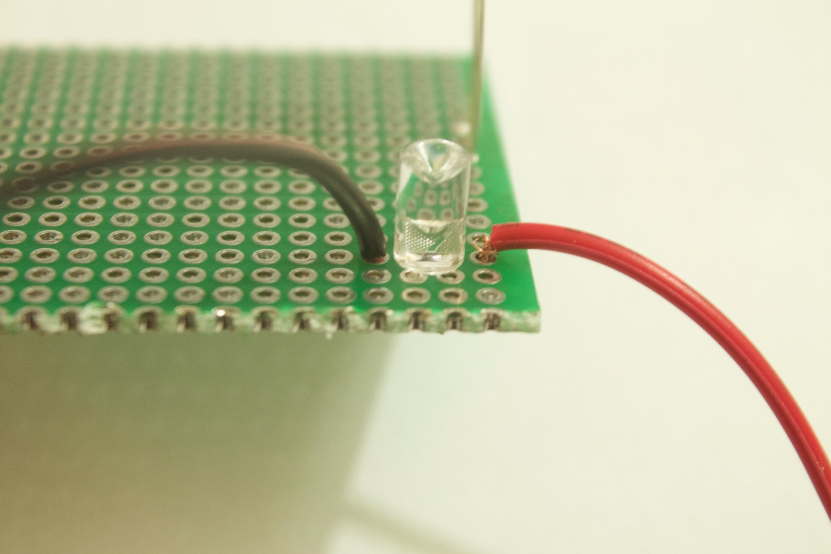
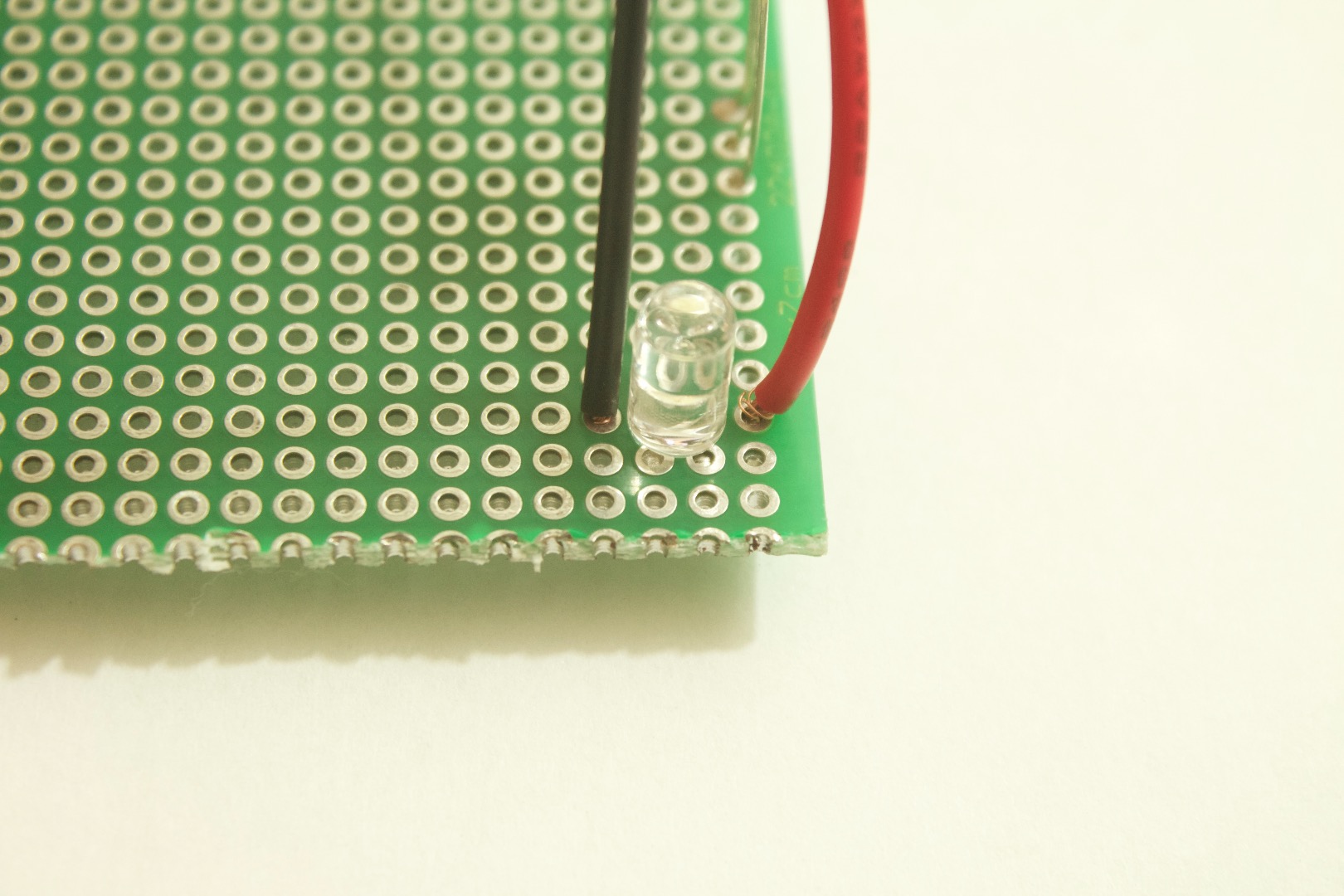
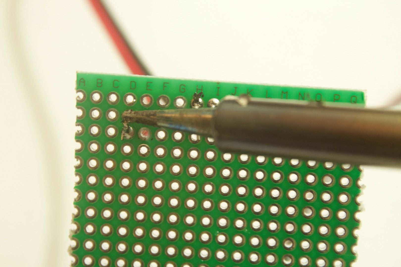
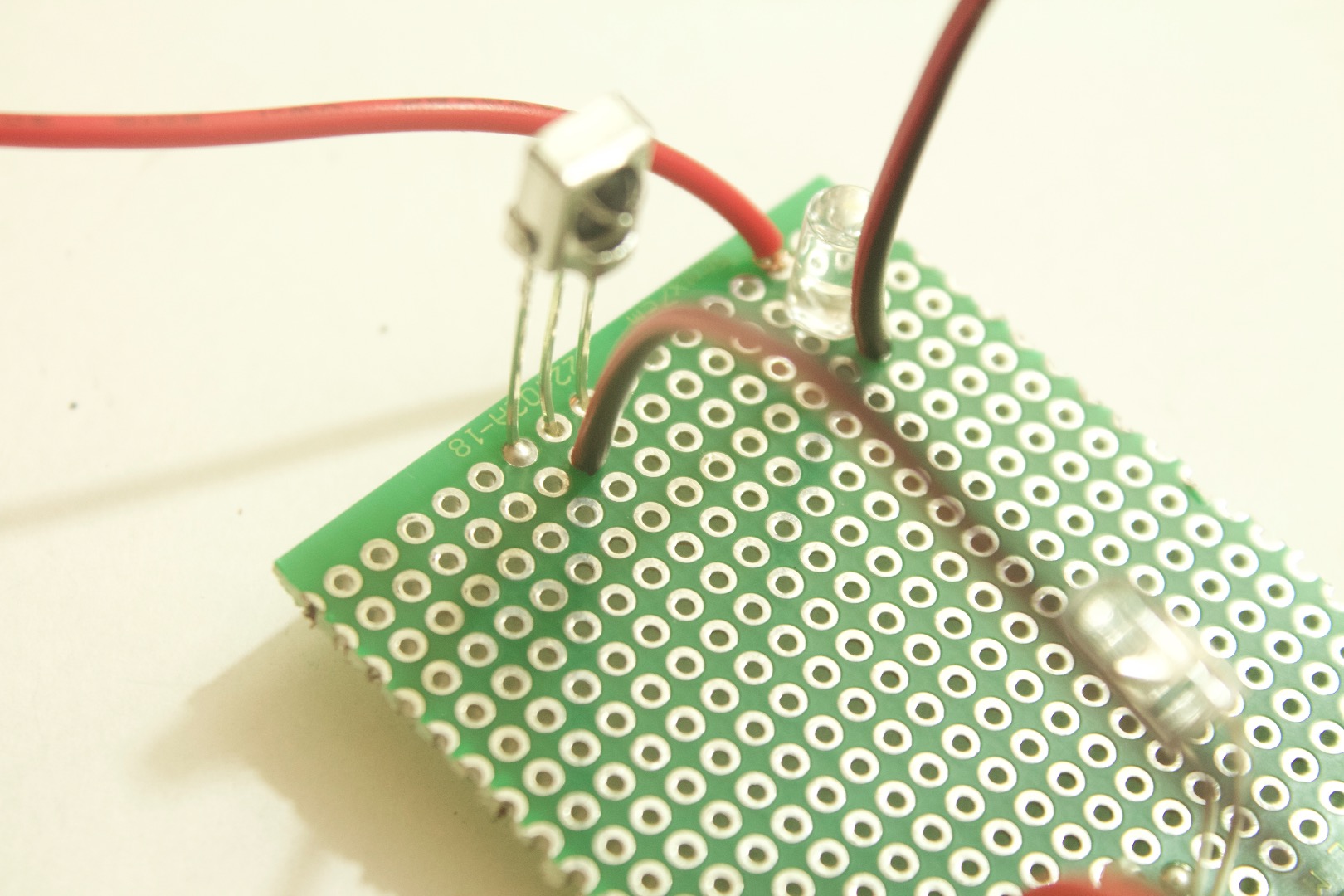
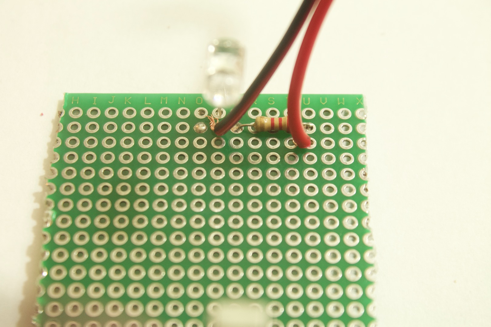
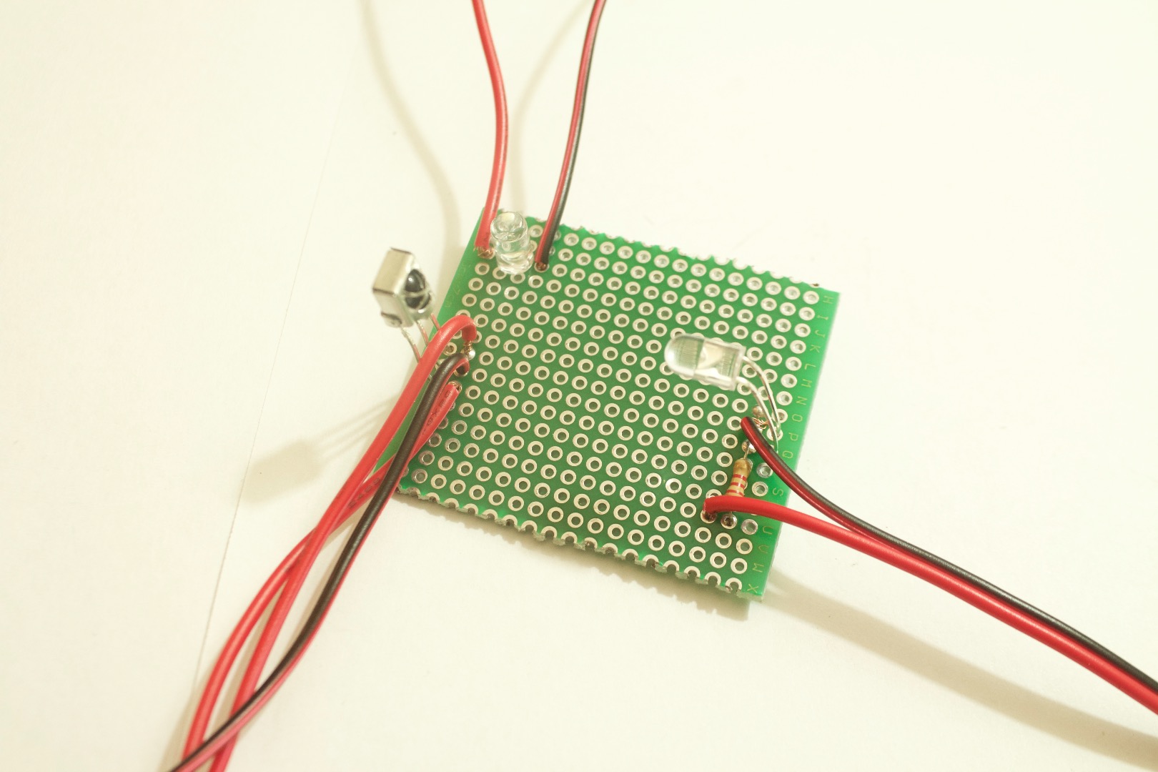
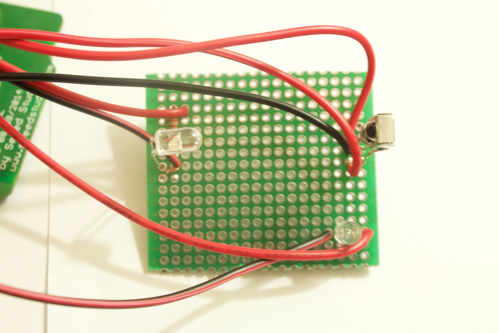
1. Solder wires to the positive and the negative pins of the LED.
2. Solder signal wire on to the IR receivers pin 1.
Solder the GND wire to the pin 2 of the IR reciever (middle).
Solder a red wire(VCC) to the pin 3 of the IR receiver.
3. Solder GND to the IR leds negative pin and solder the positive wire to the other end of the resistor.
Now you are done with soldering make sure your have something that looks like the image above and then move on to programing the board.
Code It
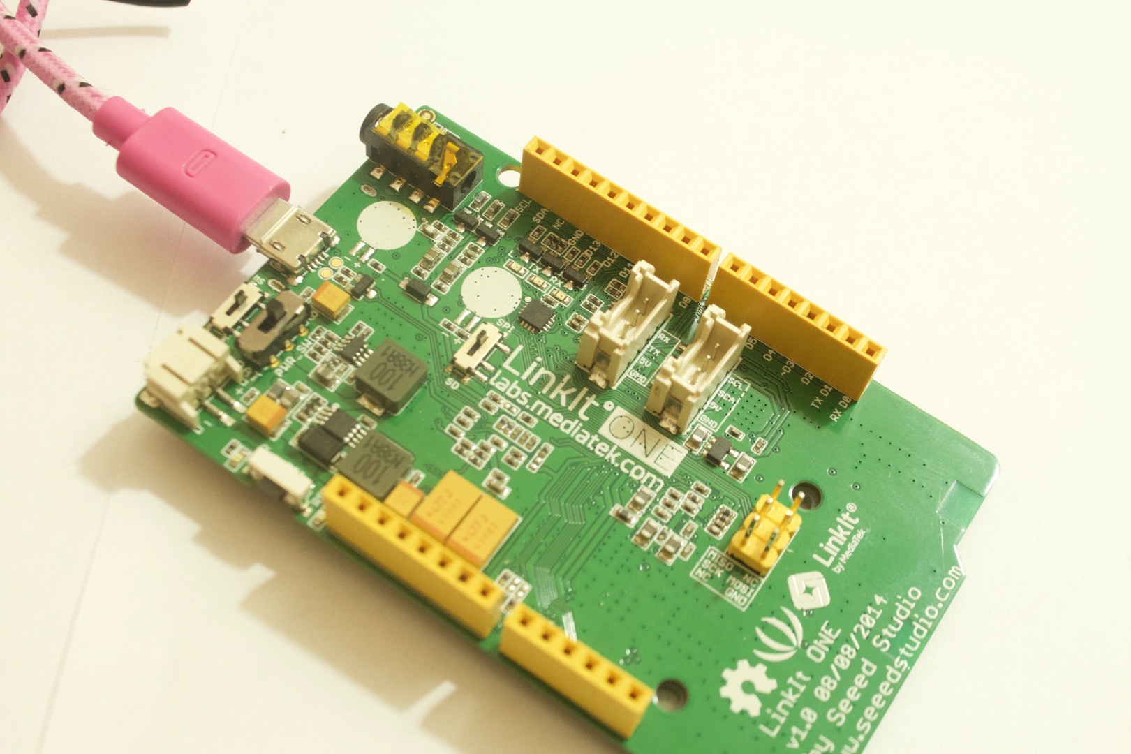
Plug in the LinkIt One into you're computer and upload this code. This code will allow the IR sensor to detect any objects in between the sensor and the led, and when interrupted the LED will light up and start blinking. You can change it to do what it is you want to do when the object is detected.( triggering a servo, turning on a relay...).
Here is the code:
int Wled = 13;// initialize the pins
int IRled= 8;
int IRsensor = 2;
int ir;
void setup()
{
pinMode(Wled, OUTPUT);
pinMode(IRled, OUTPUT);
pinMode(IRsensor, INPUT);
signal38();
}
void loop()
{
signal38();
if(ir == 1)
{
digitalWrite(Wled, HIGH);
delay(300);
digitalWrite(Wled, LOW);
delay(300);
}
else if(ir == 0 )
{
digitalWrite(Wled, LOW);
}
}
void signal38()
{
digitalWrite(IRled, HIGH);
delayMicroseconds(11);
digitalWrite(IRled,LOW);
delayMicroseconds(11);
digitalWrite(IRled, HIGH);
delayMicroseconds(11);
digitalWrite(IRled,LOW);
delayMicroseconds(11);
digitalWrite(IRled, HIGH);
delayMicroseconds(11);
digitalWrite(IRled,LOW);
delayMicroseconds(11);
digitalWrite(IRled, HIGH);
delayMicroseconds(11);
digitalWrite(IRled,LOW);
delayMicroseconds(11);
}
Wire It
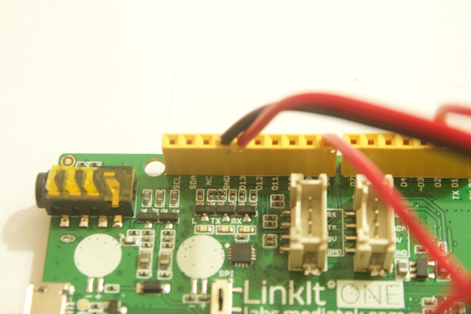
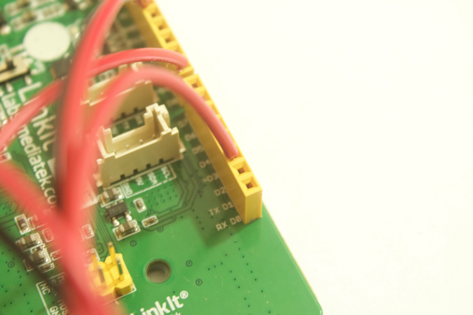
1. Wire the LED to pin 13
2. Wire the IR led to pin 8.
3. GND to GND, IR sensors VCC to 3.3v and IR signal to pin 2.
Make sure you use resistors to lower the current if your Component is rated lower than what the LinkIt One outputs, if precaution is not taken your component can and will burn out.
And you are done:). All that left to do is test it. Make sure you have all the joints soldered properly and that no pins are bridging.
Test It and Conclusion
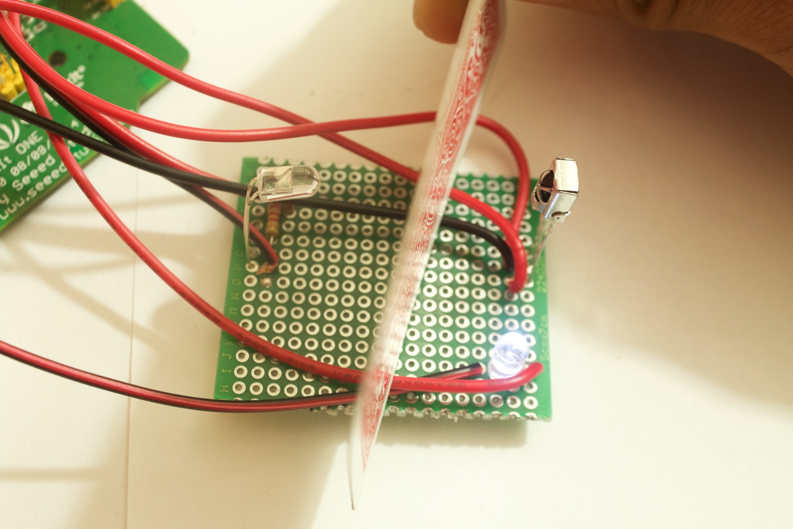
Plug in the LinkIt one into a power source and test out your project. If everything is right then now when you put your hand in between the sensor and the IR led the LED will start blinking.
Hope you learned something new and if you have any questions feel free to ask them in the comments below.
In Conclusion this is a simple project which only triggers on a LED, but you could use the data from the IR sensor and make it turn on or off much more based on the state of the sensor.