LinkIt One Capacitive Tutorial
by robo10302 in Circuits > Microcontrollers
1099 Views, 7 Favorites, 0 Comments
LinkIt One Capacitive Tutorial
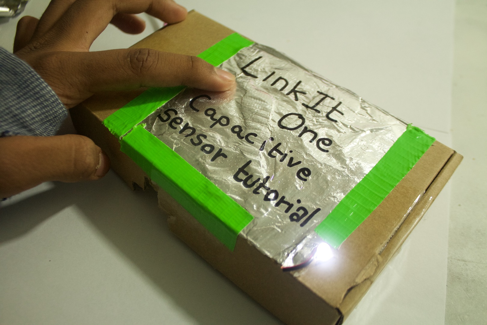
Hello builders! Here in this 'ible we will make a project which will use a capacitive sensor to turn on a LED. This project uses a micro controller to send and receive the signal to and from the capacitive sensor. This micro controller is called the LinkIt One Board.
How does a capacitive sensor work?
A capacitive sensor works on the human body's ability to store small amounts of charges and then give away. So when we get close to the the sensor the signal going through the foil back to the LinkIt One board changes.
Parts
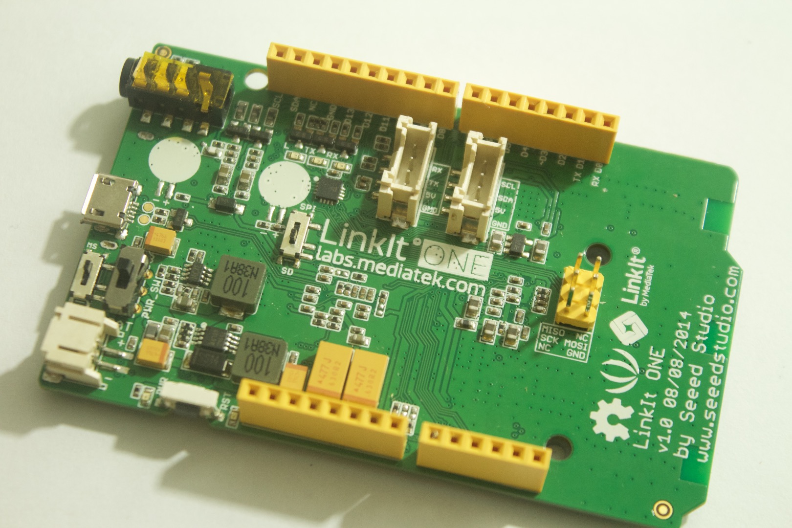

1. LinkIt One Board
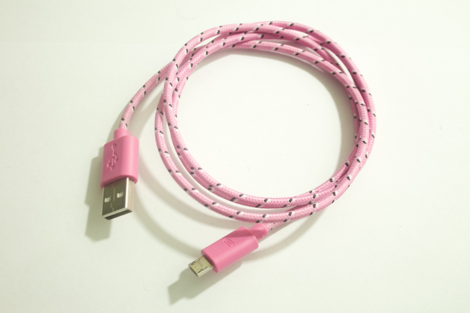
2. USB Board
3. Aluminum Foil
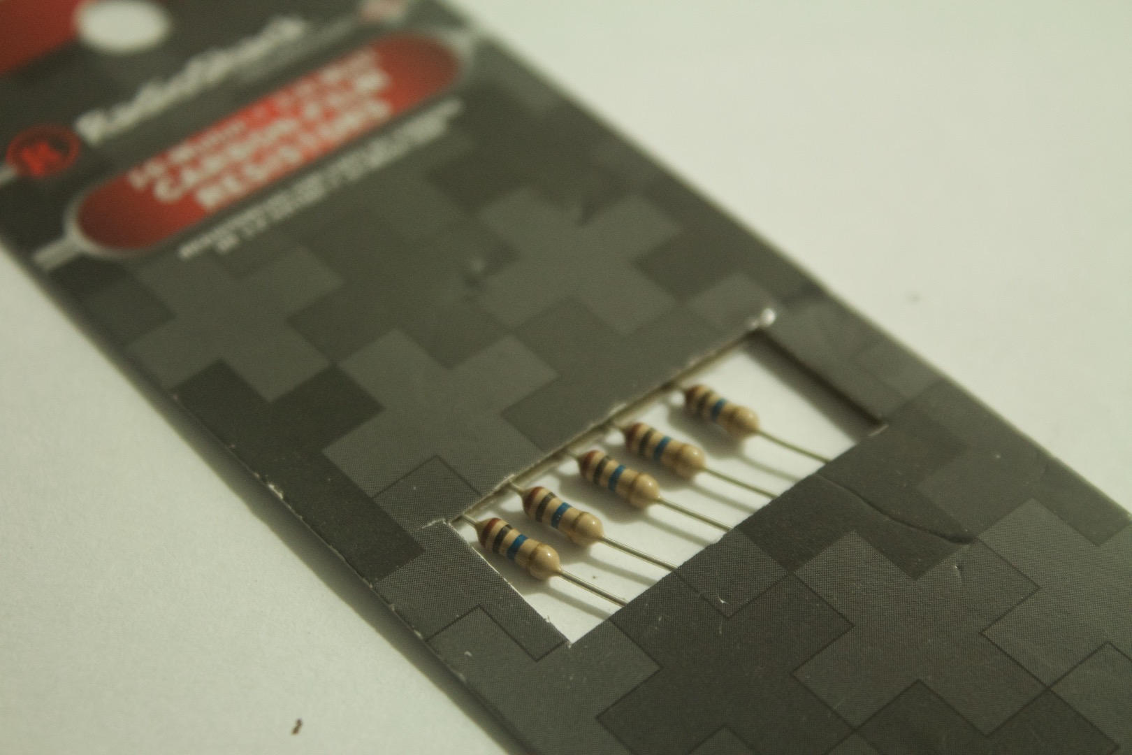
4. 10 Mega Ohm Resistor
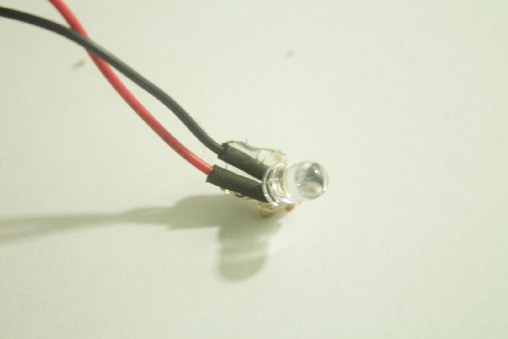
5. LED (any color)
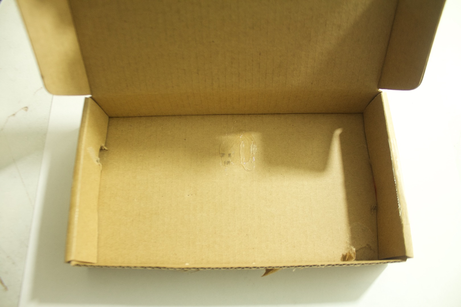
6. Box
Foil
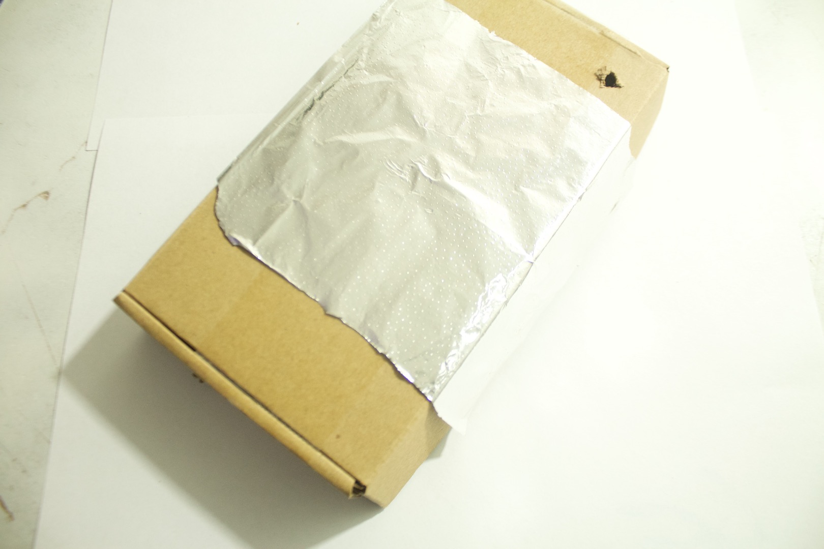
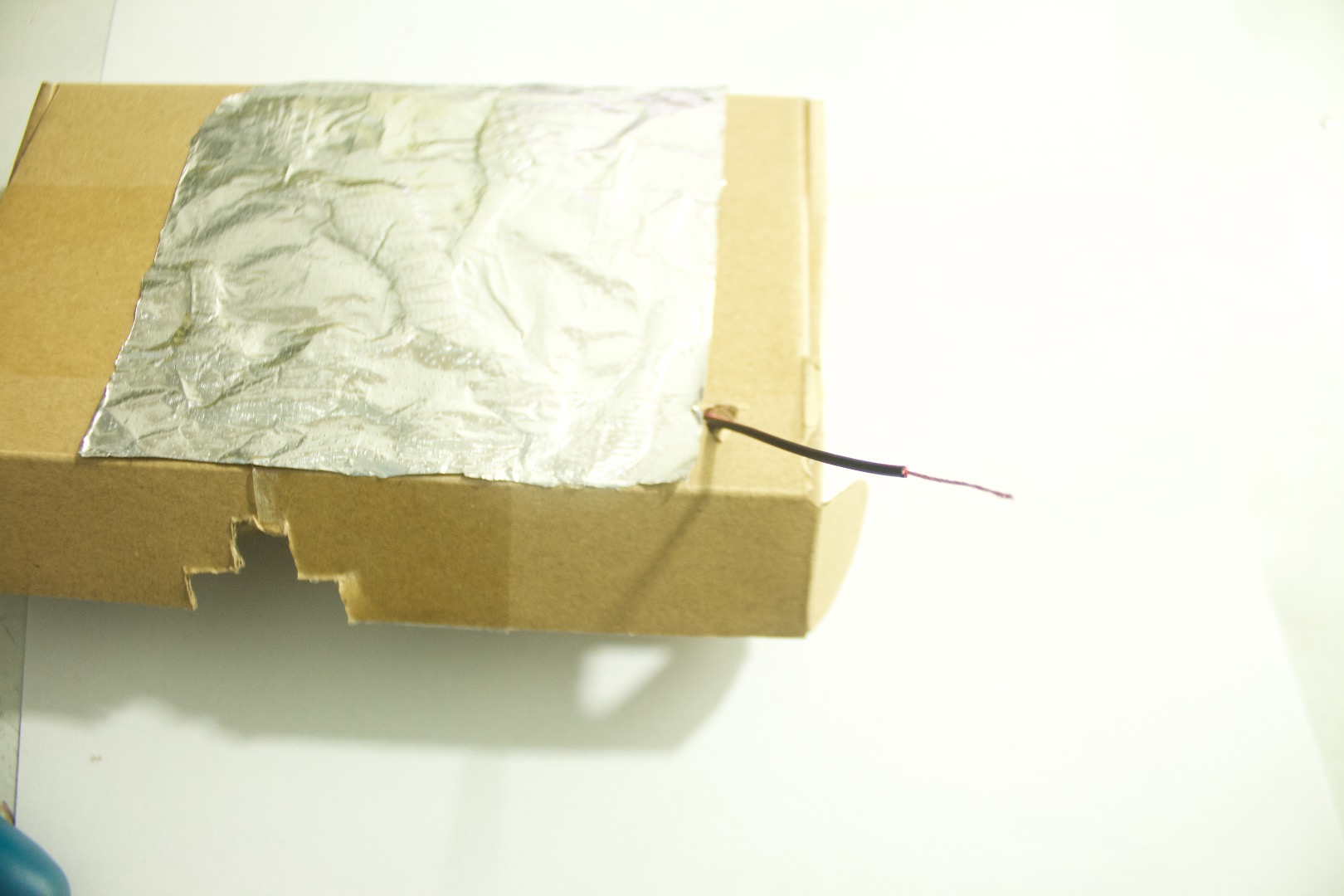
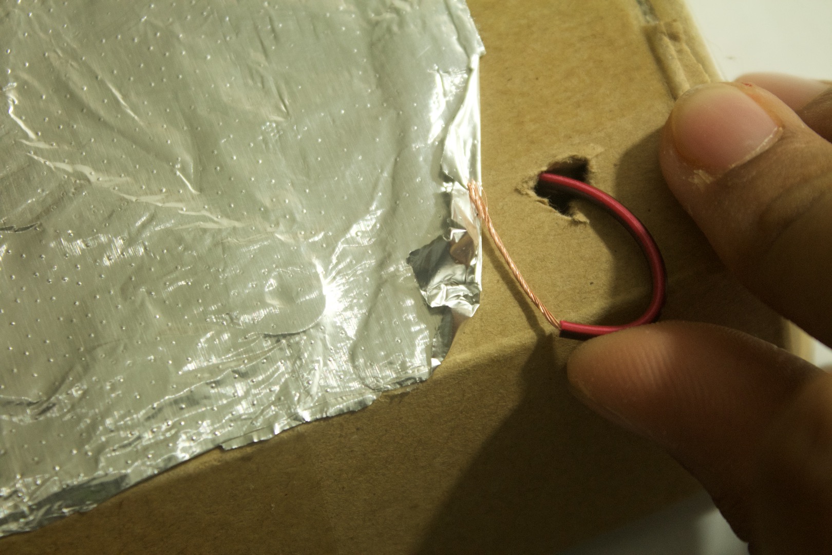
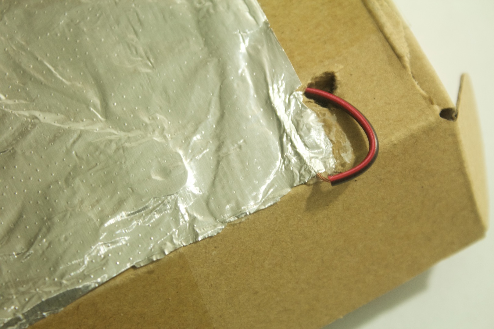
1. Hot glue the foil on top of the box.
2. Cut of the excess foil.
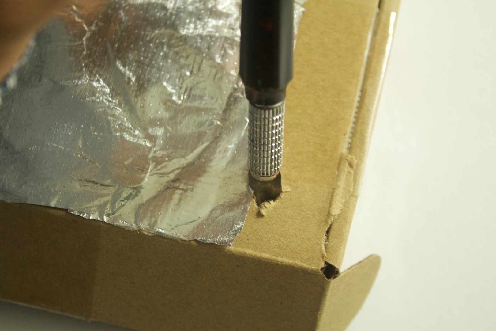
3. Make a hole next to one of the edges.
4. Put a wire through the hole and strip a long part near the foil.
5. Hot glue the wire to the foil making sure that it doesn't move and has conductive contact with the foil.
LED
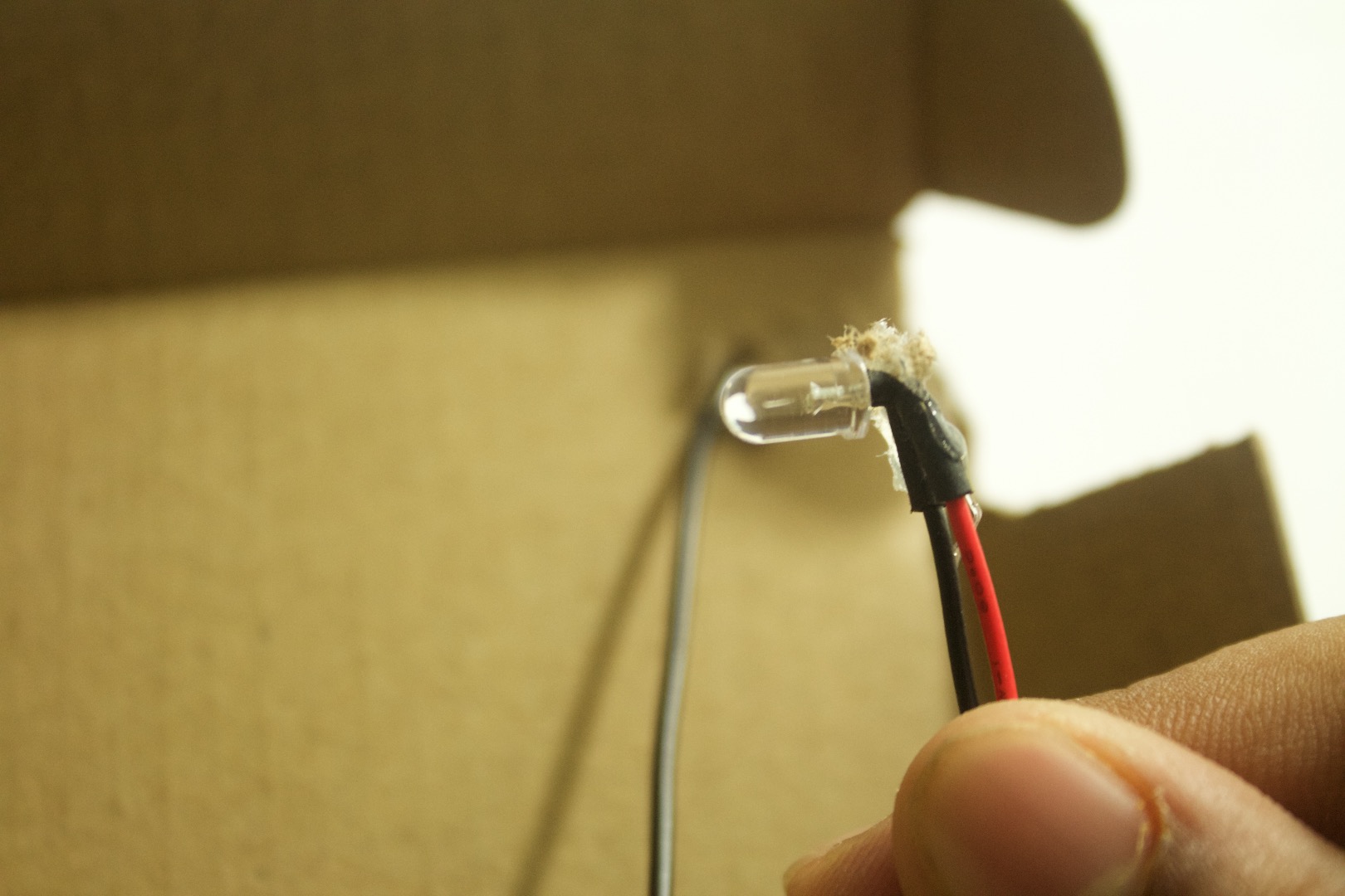
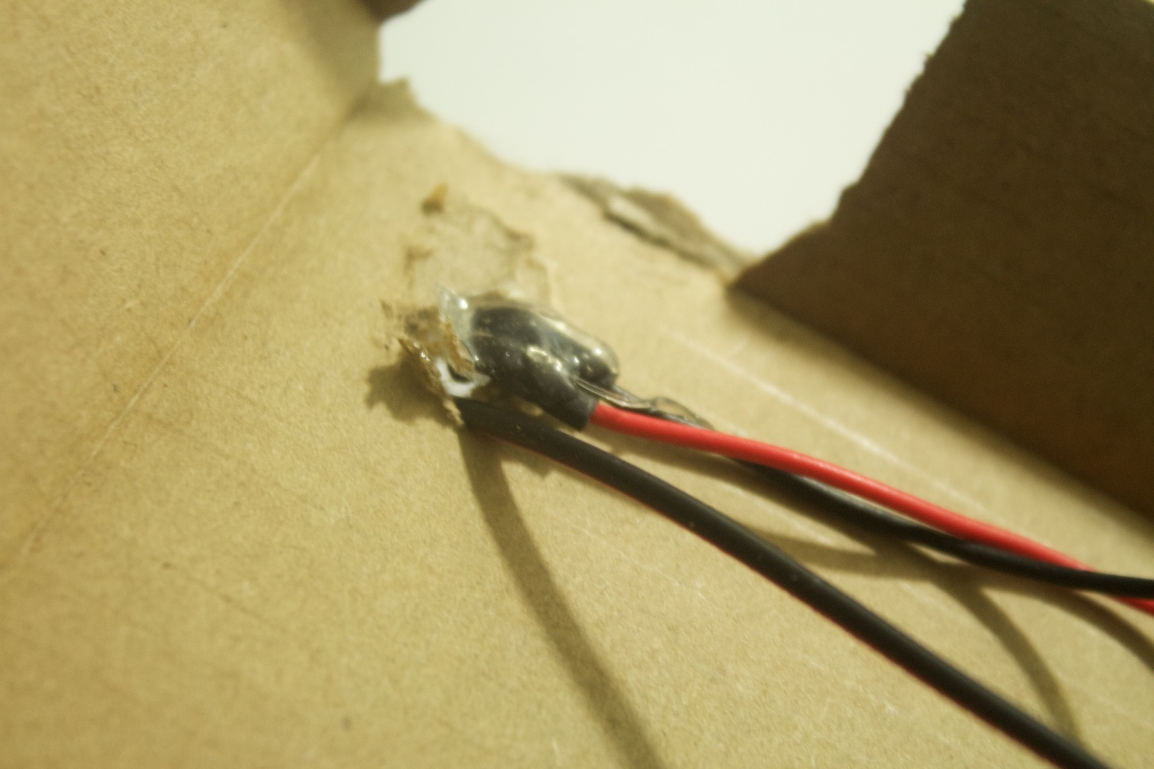
1. Insert the LED in the same hole as the capacitive signal wire.
2. Hot glue it to the hole.
3. Solder wires to the positive and the negative pins on the LED.
USB
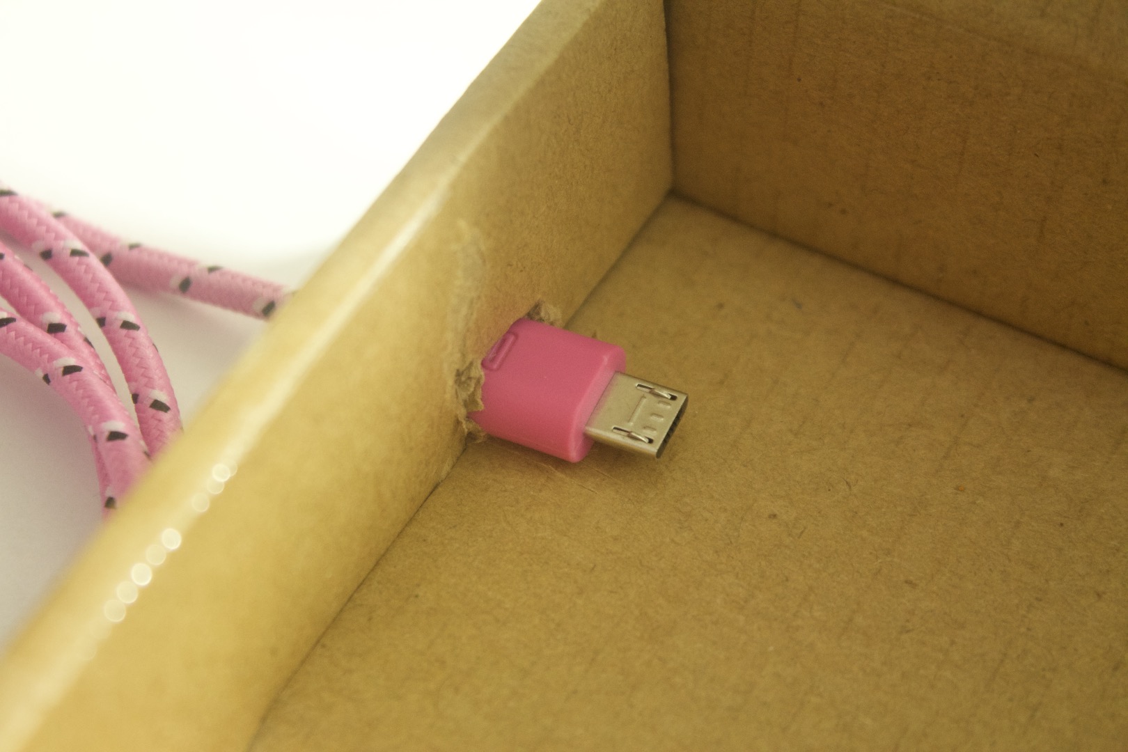
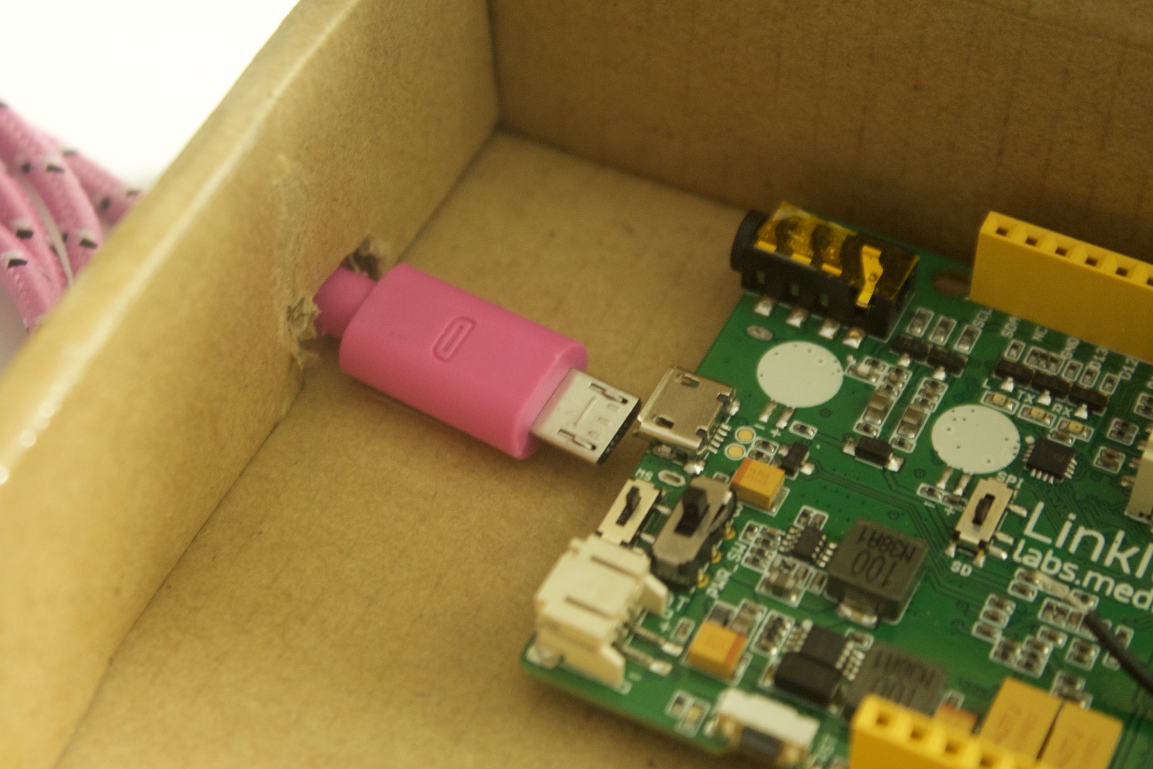
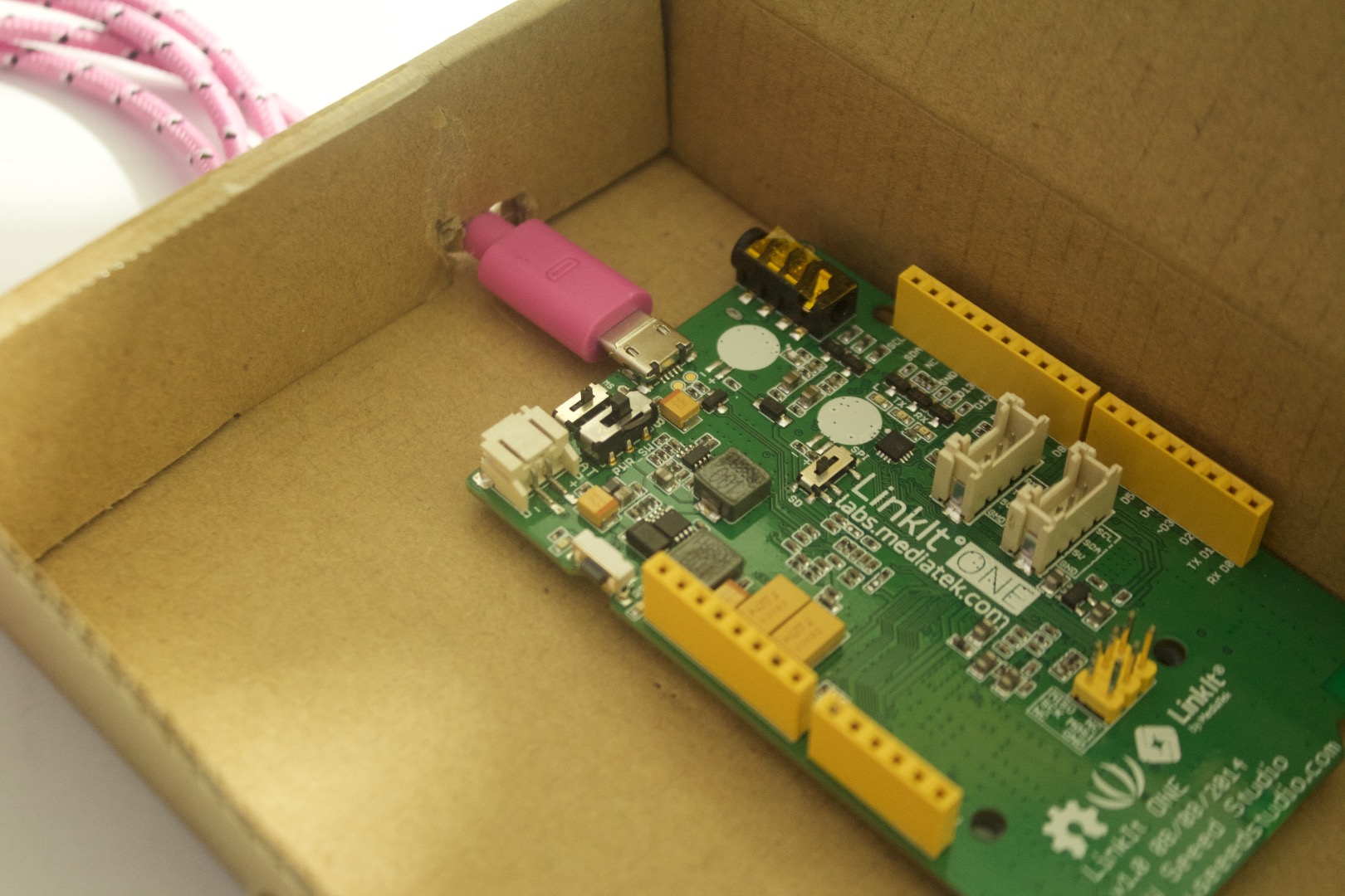
1. Make a Hole for the Usb cable to seek through.
2. Now hot glue the board to the base. ( Make sure you use little)
Code
Lets code the board such that the led turns on when the capacitive sensor comes in touch with the finger.
Before that download this library and put it in your libraries folder in the Arduino folder.
http://playground.arduino.cc/Main/CapacitiveSensor?from=Main.CapSense
Code:
#include <Capacitive.Sensor.h>
CapacitiveSensor capsensor = CapacitiveSensor(8,12);
int LED = 13;
void setup()
{
capsensor.set_CS_AutocaL_Millis(0xFFFFFFFF);
}
void loop()
{ long start = millis();
long TouchVal = capsensor.capacitiveSensor(25);
if(TouchVal > 1000) // change this number here to change the distance from which the led will turn on.
{
digitalWrite(LED, HIGH);
}
}
Upload the code and move on to wiring it.
Wiring
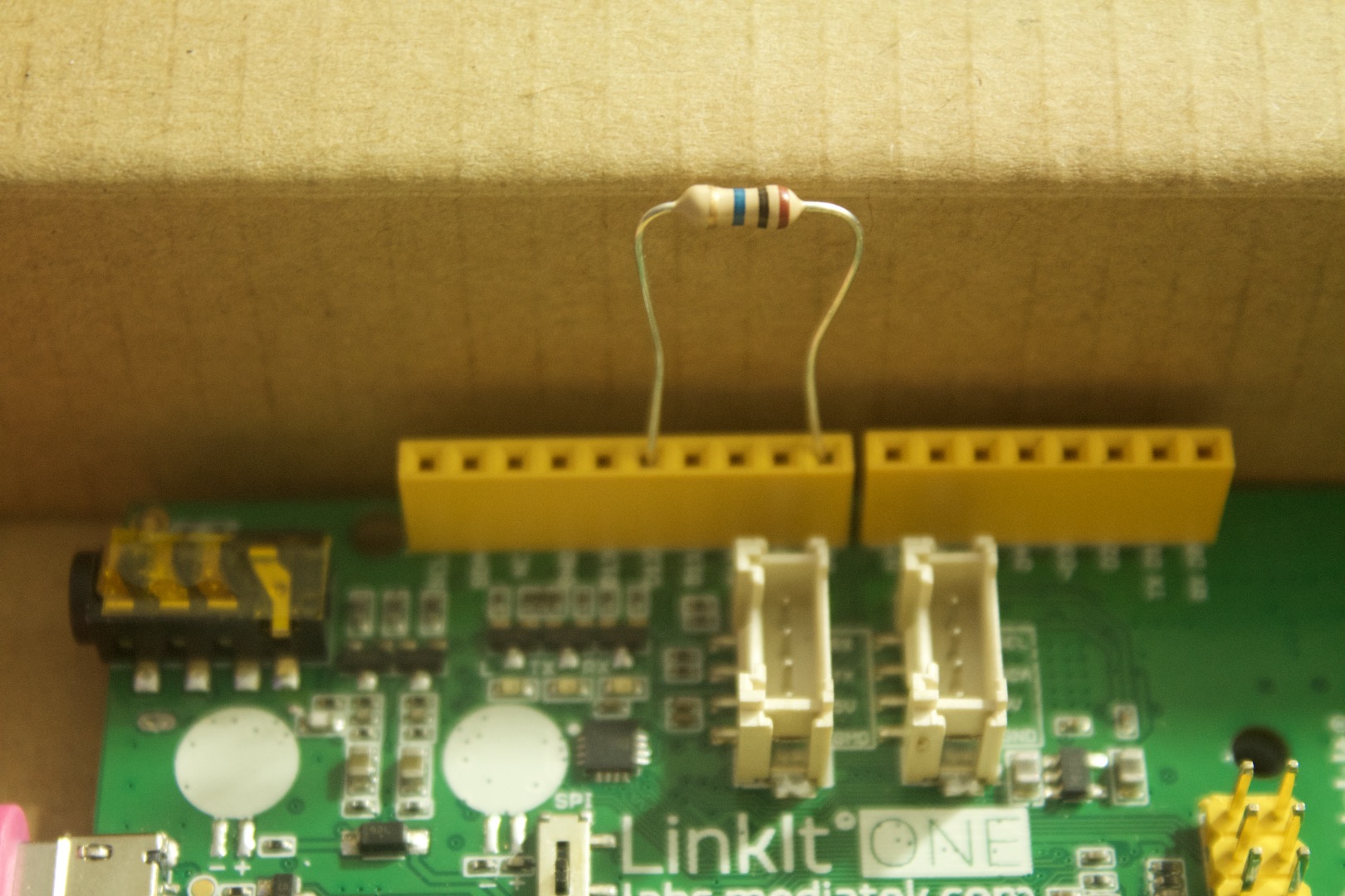
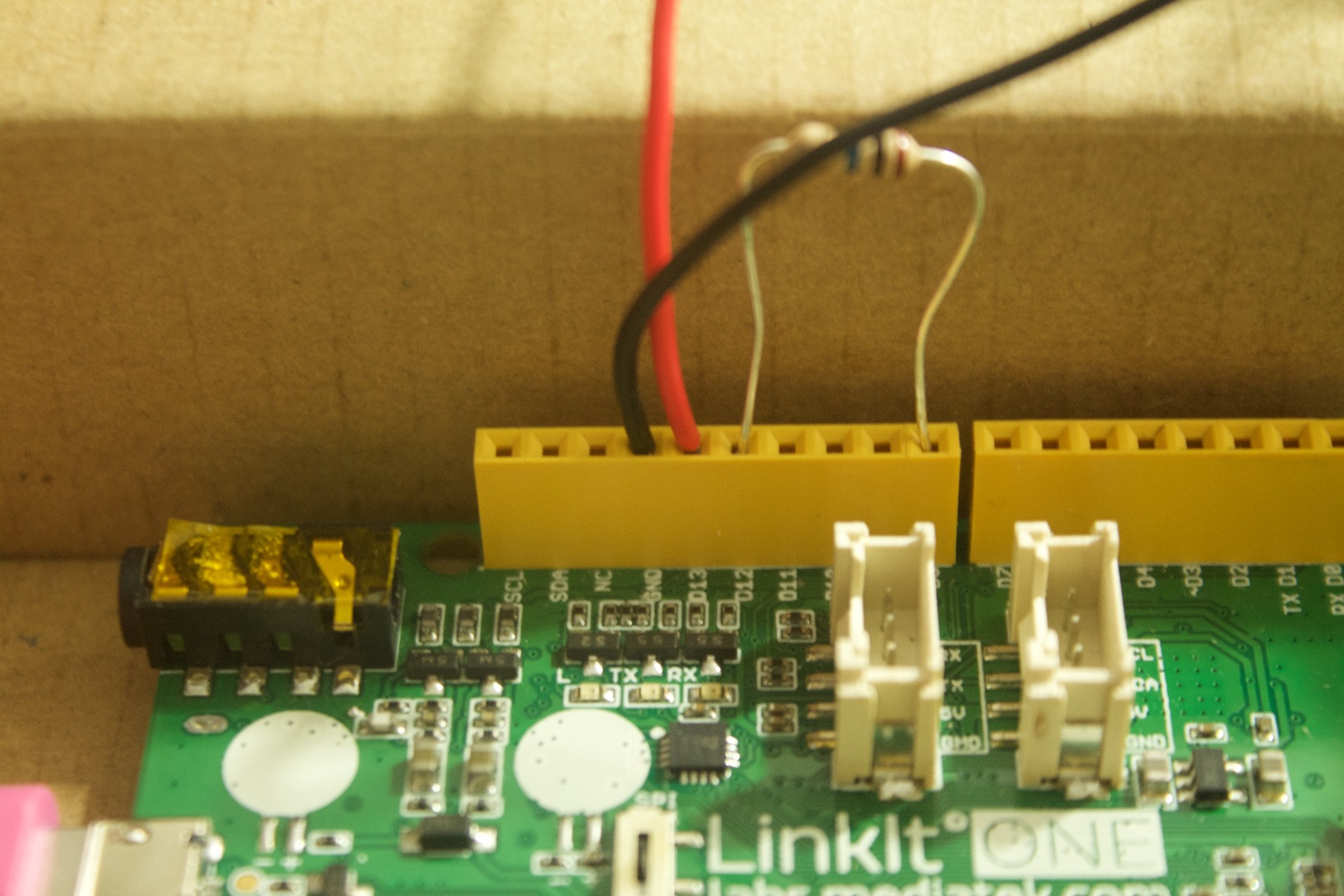
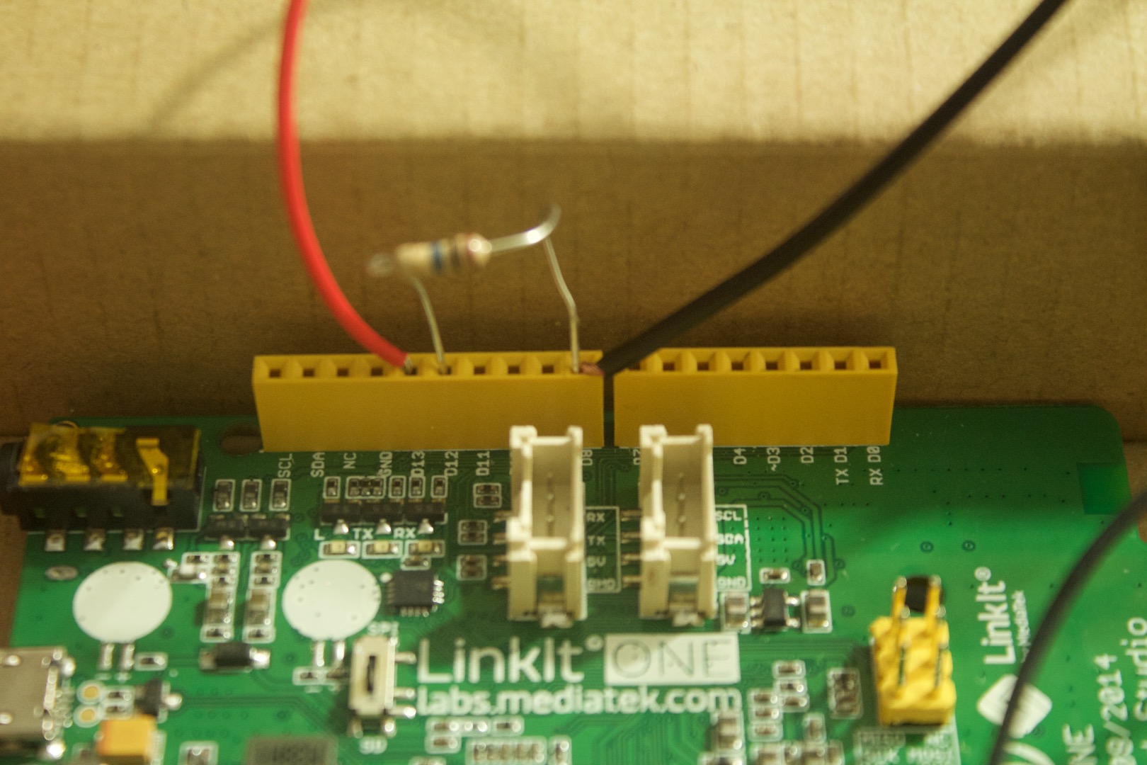
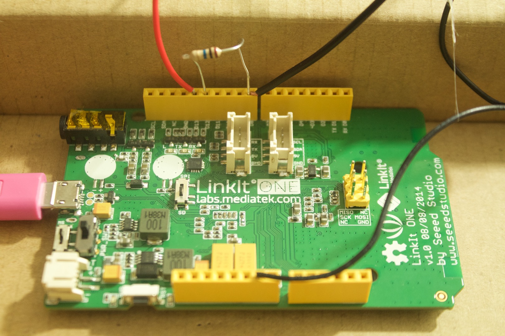
1. Connect the LED to pin 13.
2. Connect the negative of LED to GND.
3. Connect the 10m resistor between pins 8 and 12.
4. Insert the wire from the foil in pin 12.
And thats it:) You are done with the wiring. Now lets make it pretty and test it out.
Tape(Optional)
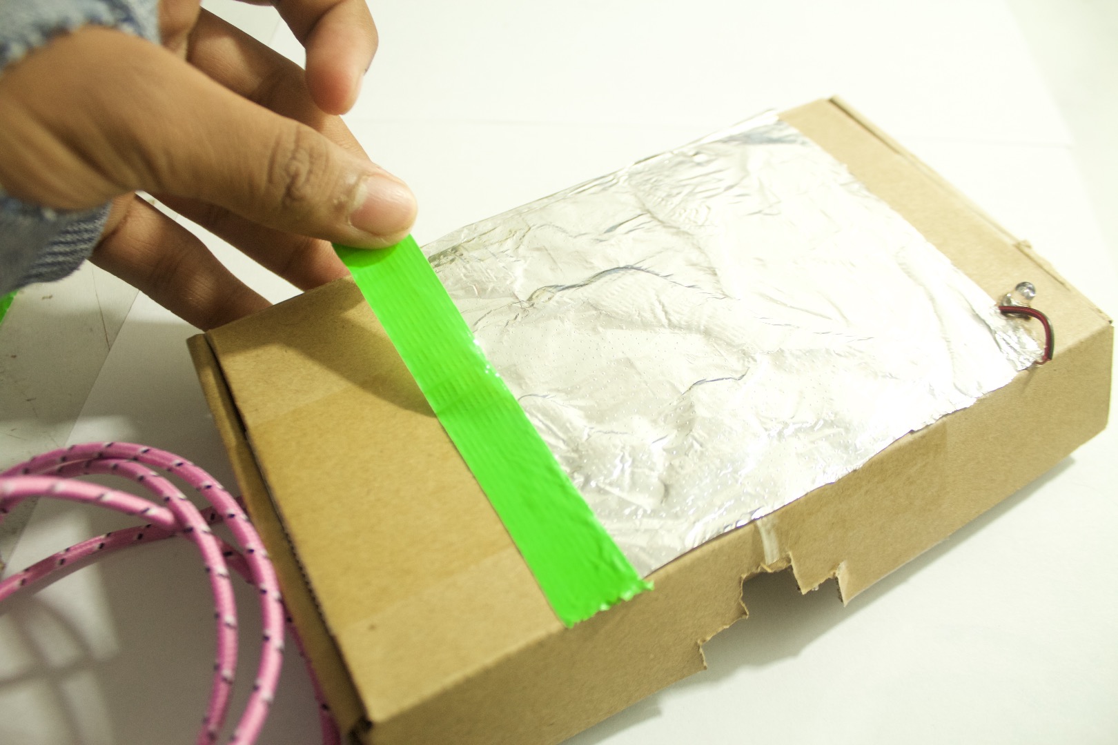
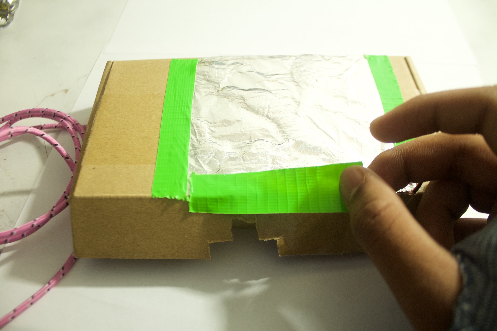
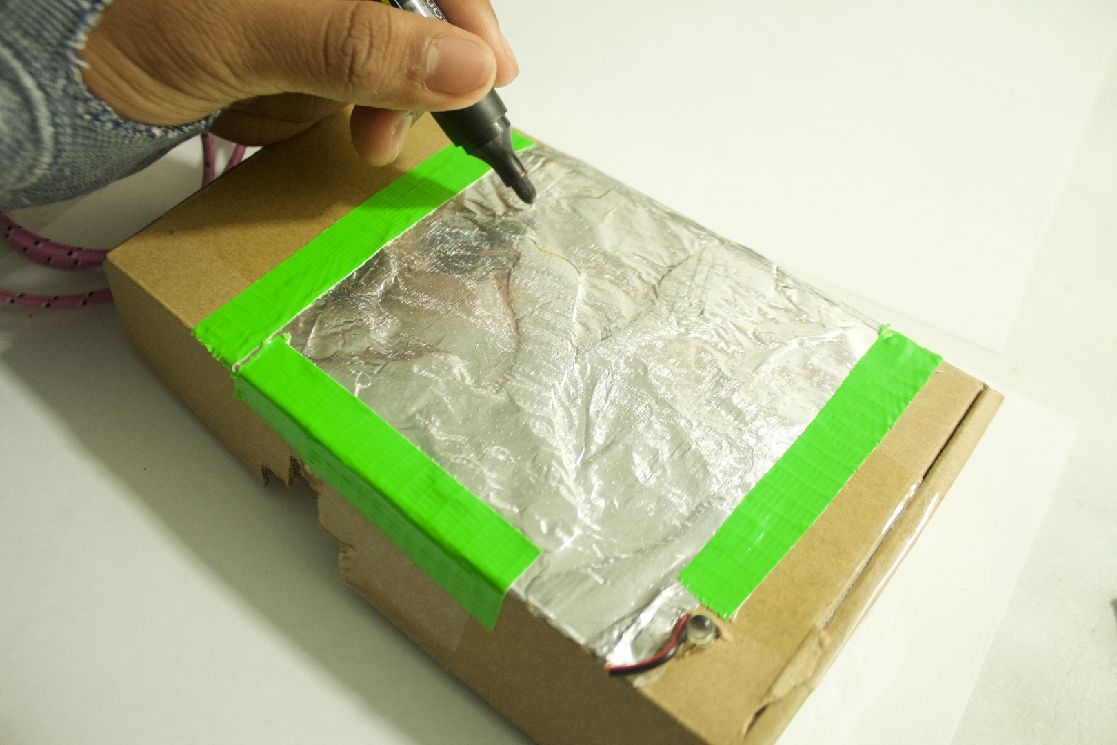
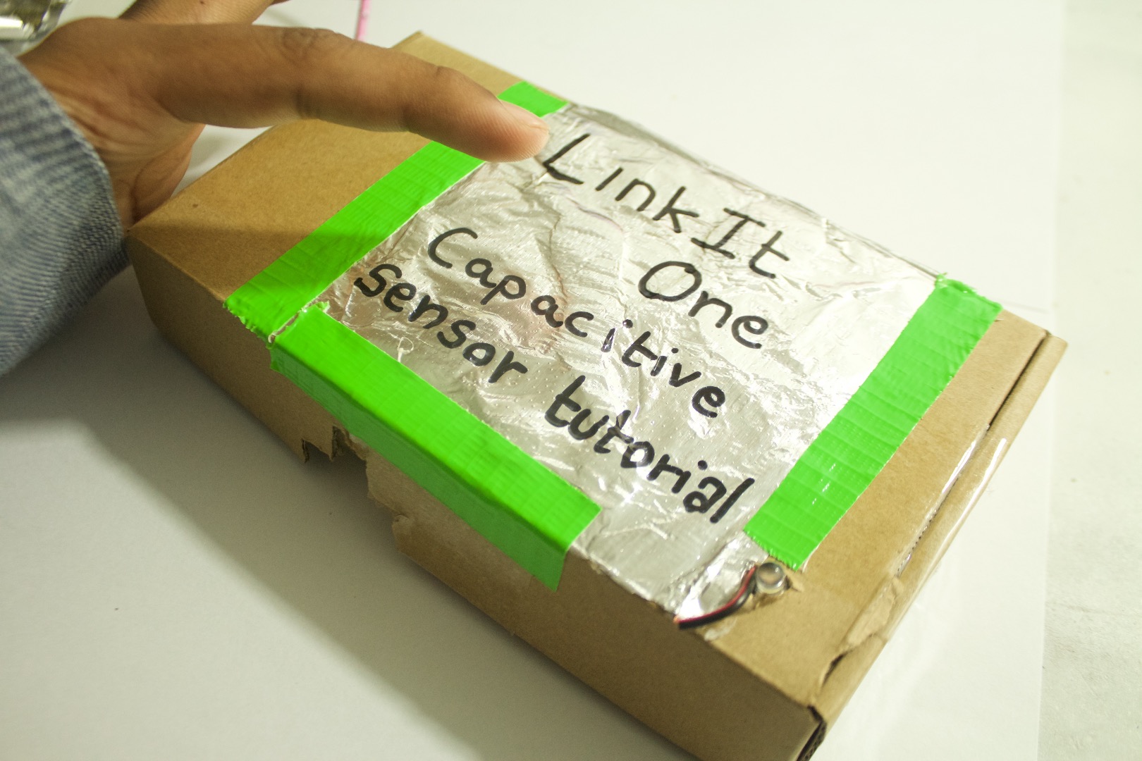
Using some colorful tape to cover the sides and make the sensor look pretty.
2. Then write something on the foil. ( BUTTON, Zombie killer... etc)
Test and Conclusion
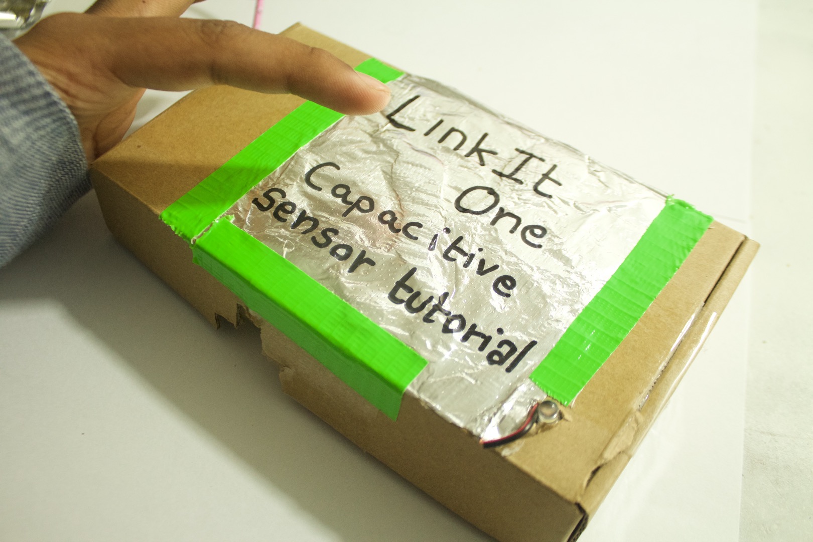
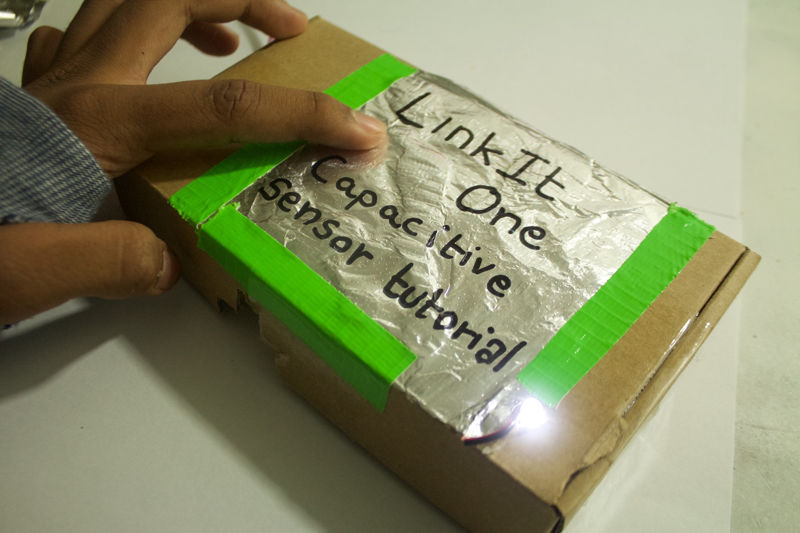
Plug in the board and test it out by touching the foil.
You can even change the sensitivity of how much distance there should be before the LED turns on.
In conclusion this project turns on a LED but you can use it to control much more ( light, fan, tv... etc)
If you have any questions feel free to ask me in the comments below.