Line Follower Robot
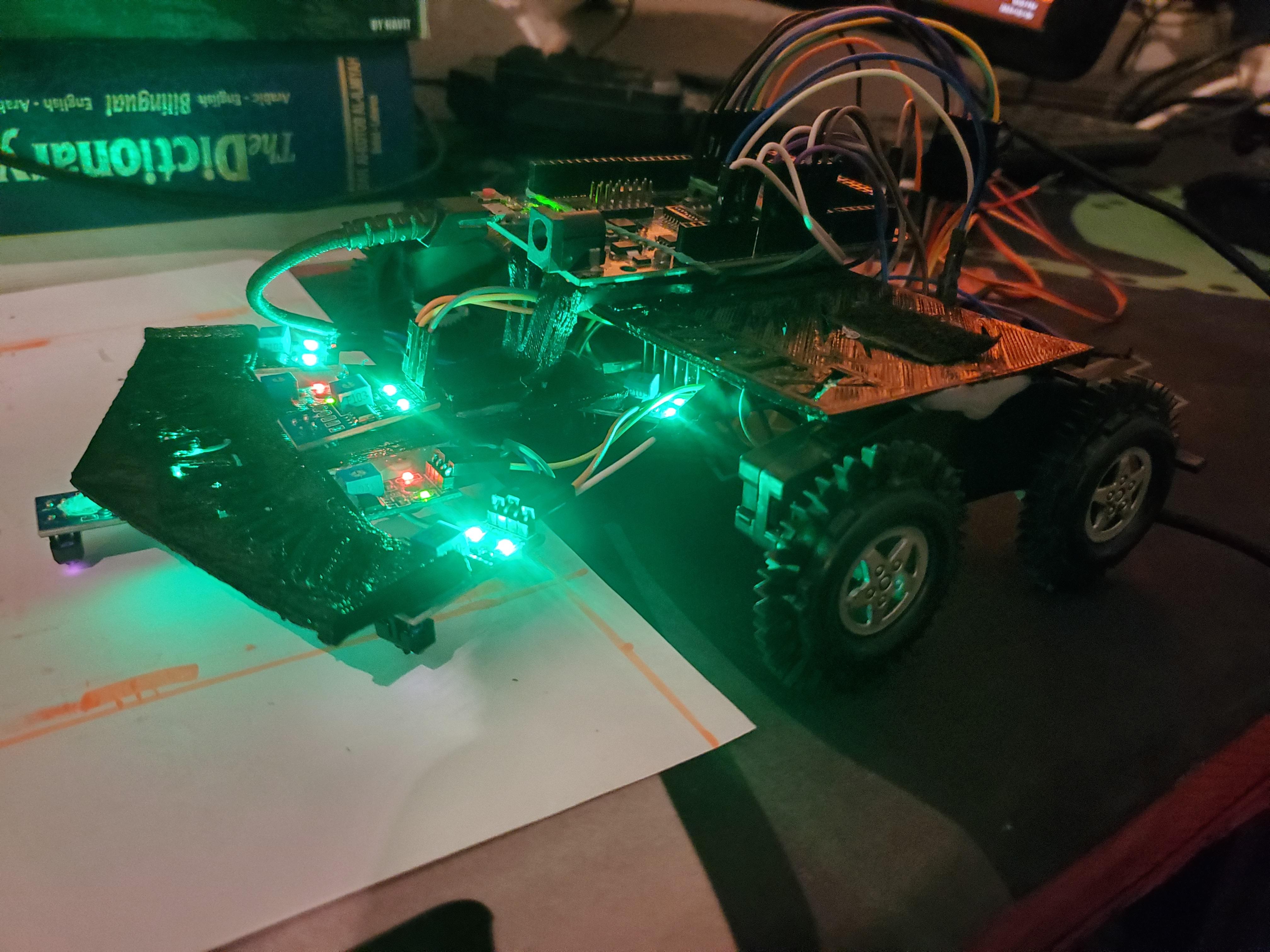
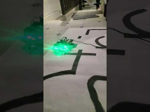
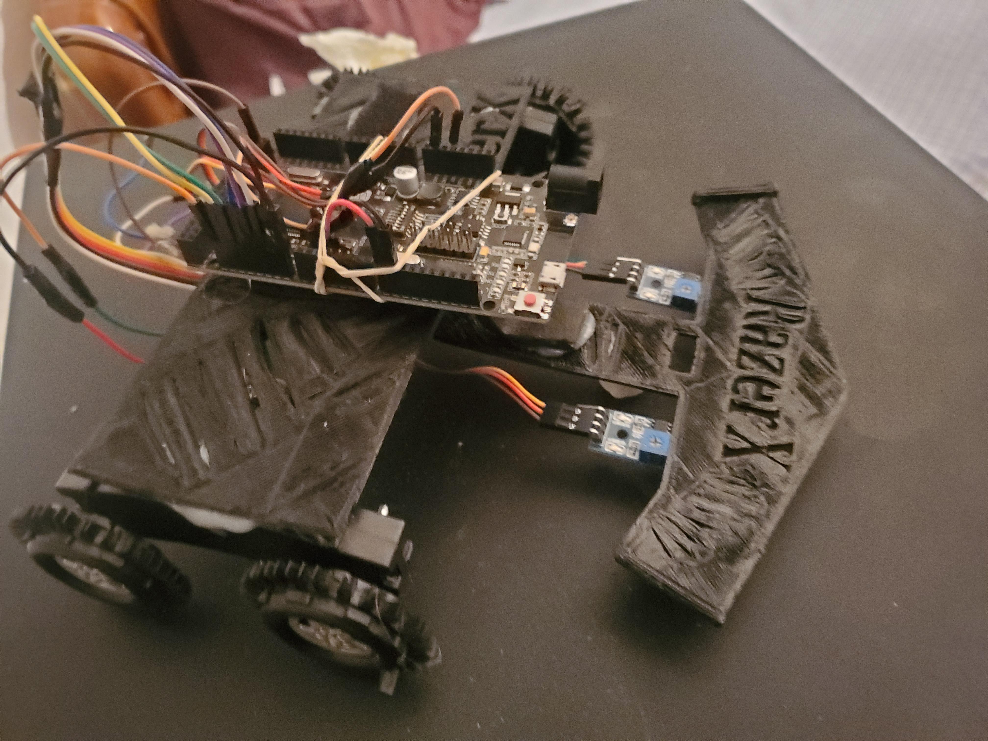
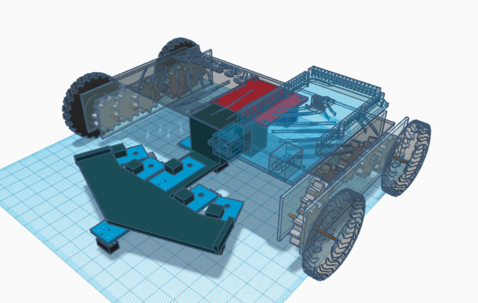
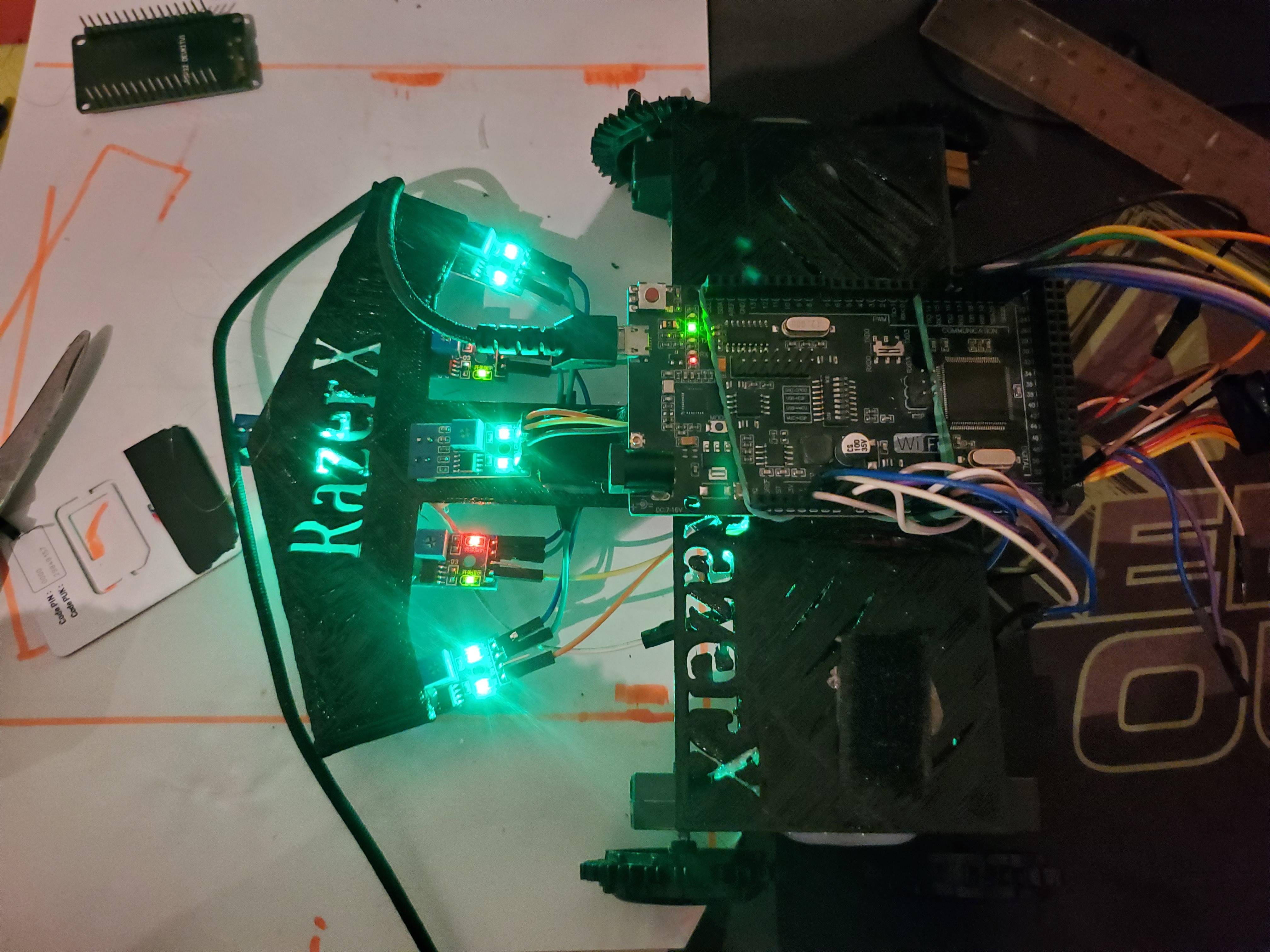
I’m excited to share my PID line follower robot, designed with 7 IR sensors, capable of following any line with precision at speeds of up to 2 m/s. I built this robot to compete in a national competition between universities, where it demonstrated both speed and accuracy. While this design has proven effective, there's always room for improvement. Now, I’m offering you the steps to create your own version and take your robotics skills to the next level. Whether you're aiming to compete or simply push the boundaries of your engineering capabilities, this project is a great way to challenge yourself and showcase your talent.
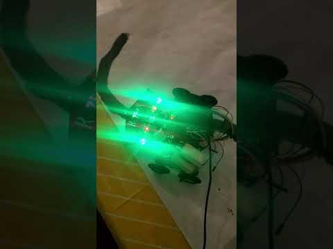
(The videos in the project showcase the robot's functionality during testing. While these clips highlight its early performance, the final version has seen significant improvements. A real map is planned for a more polished demonstration.)
Downloads
Supplies
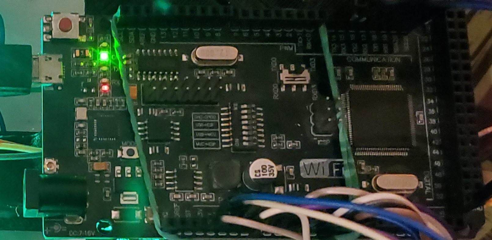
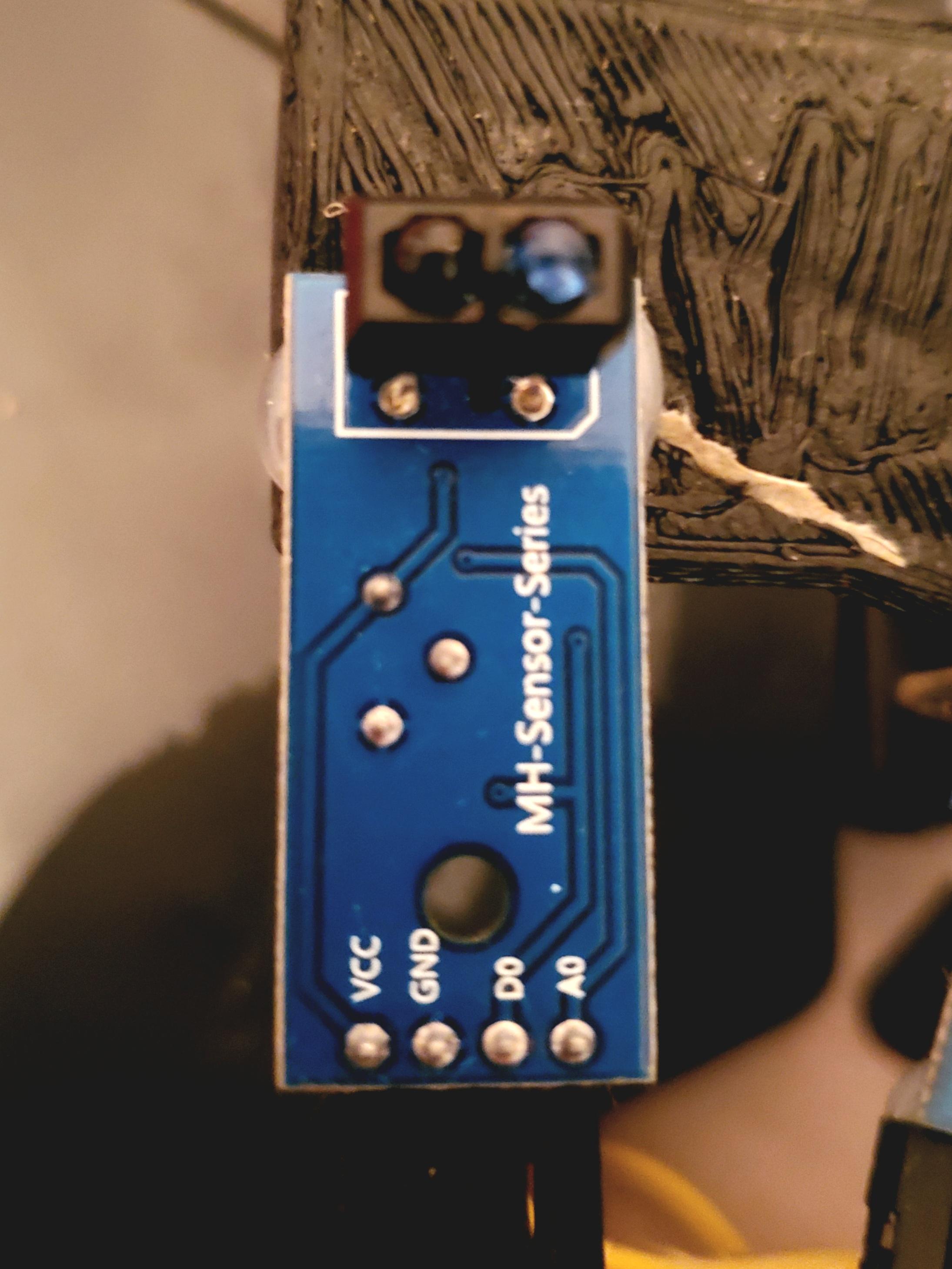
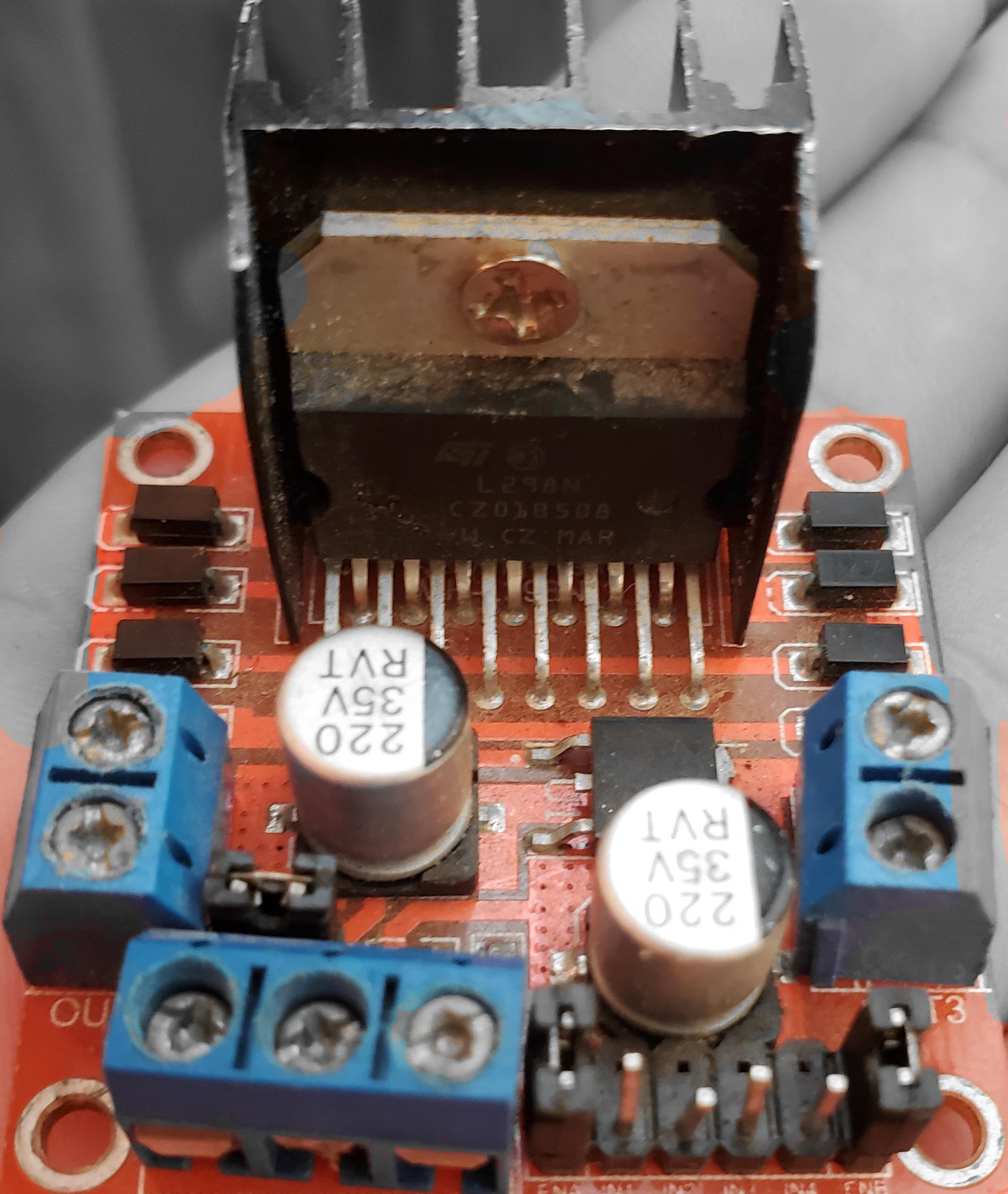
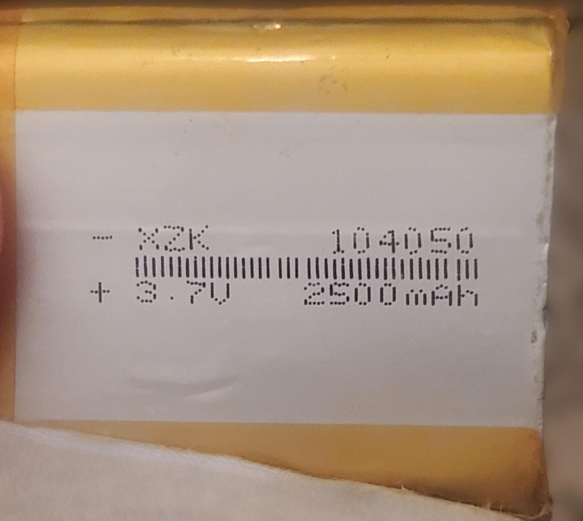
- Arduino Mega (or any compatible microcontroller)
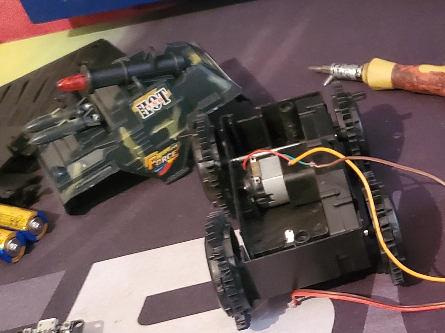
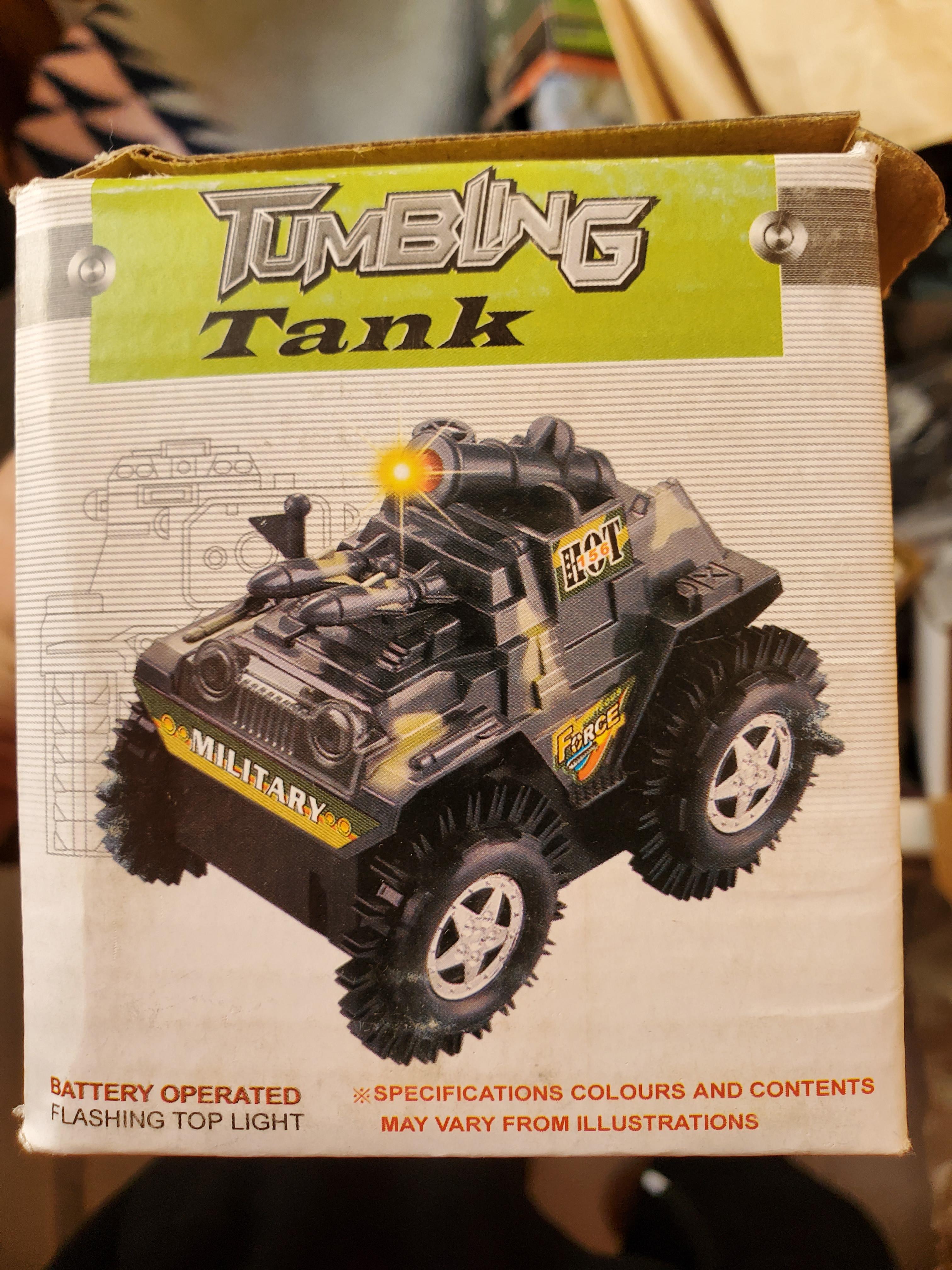
- DC Motors × 2 (I repurposed toy motors, but any suitable DC motors will work)
- IR Reflective Sensors TCRT5000 × 7 (alternative IR sensors can also be used)
- Jumper Wires for all connections
- 3D Printer for custom parts
- Motor Driver L298N (or any compatible motor driver)
- Hot Glue for securing components
- 7V+ Power Supply (I used two 3.7V LiPo batteries)
Downloads
3D Printing
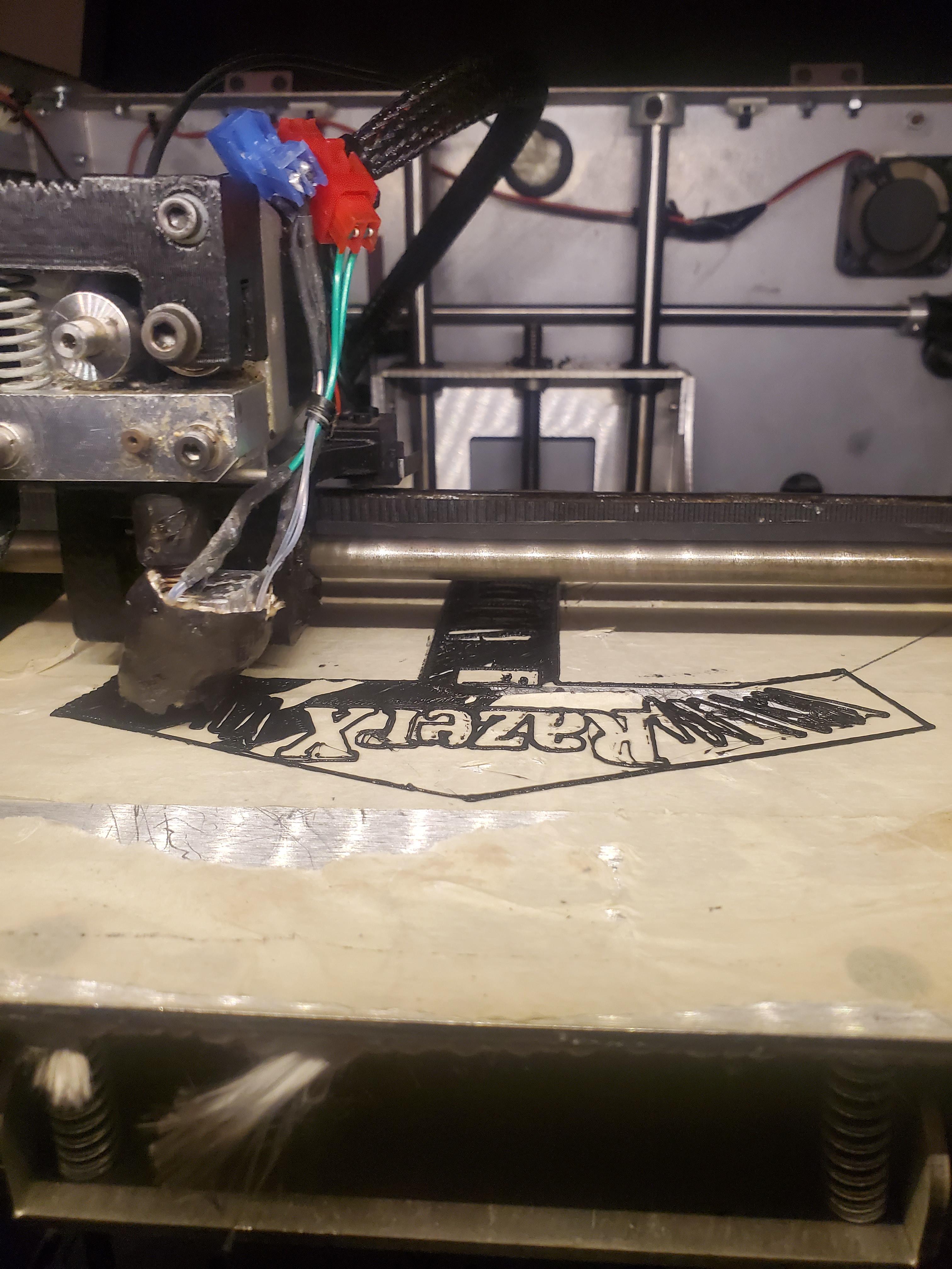
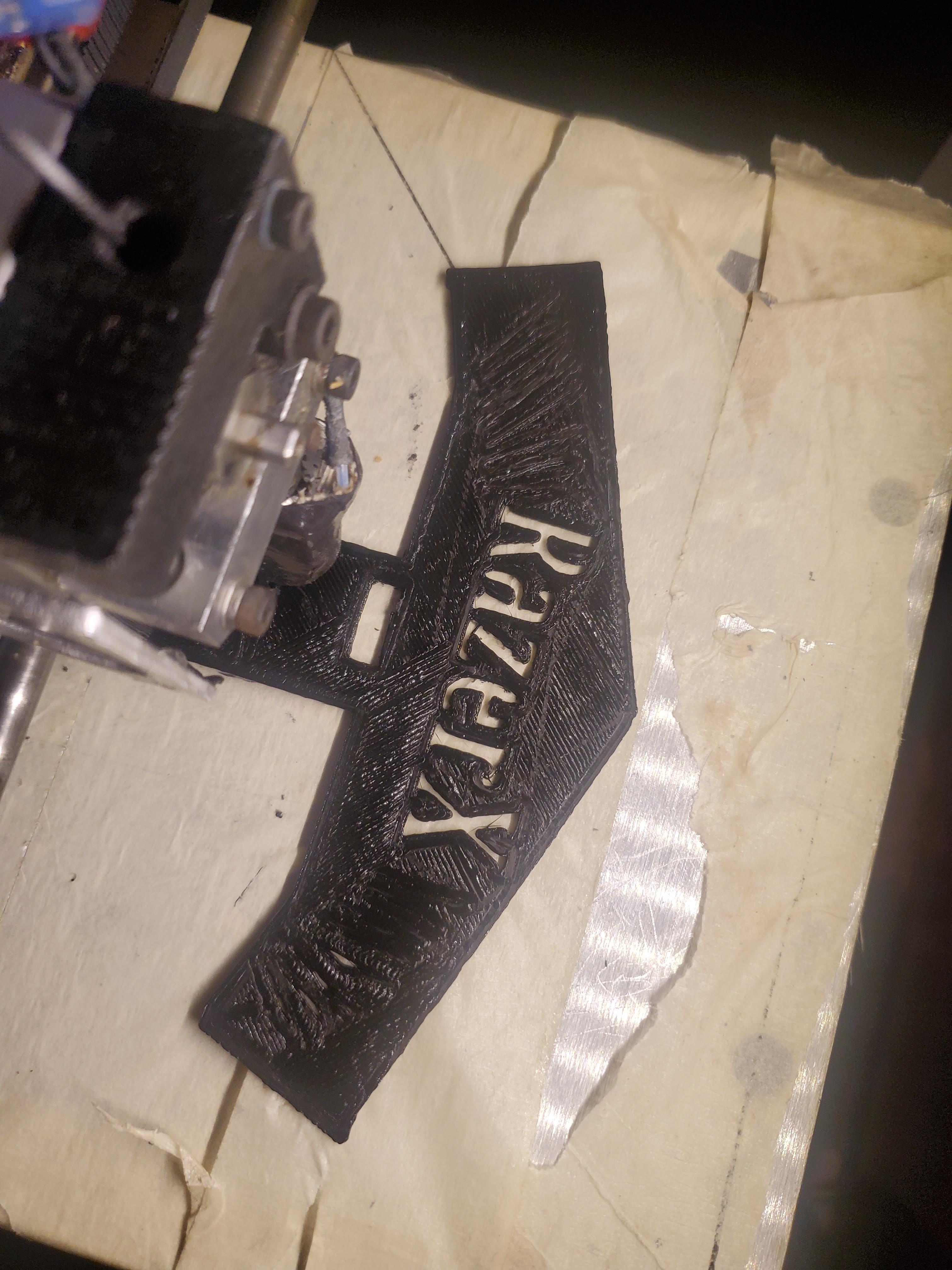
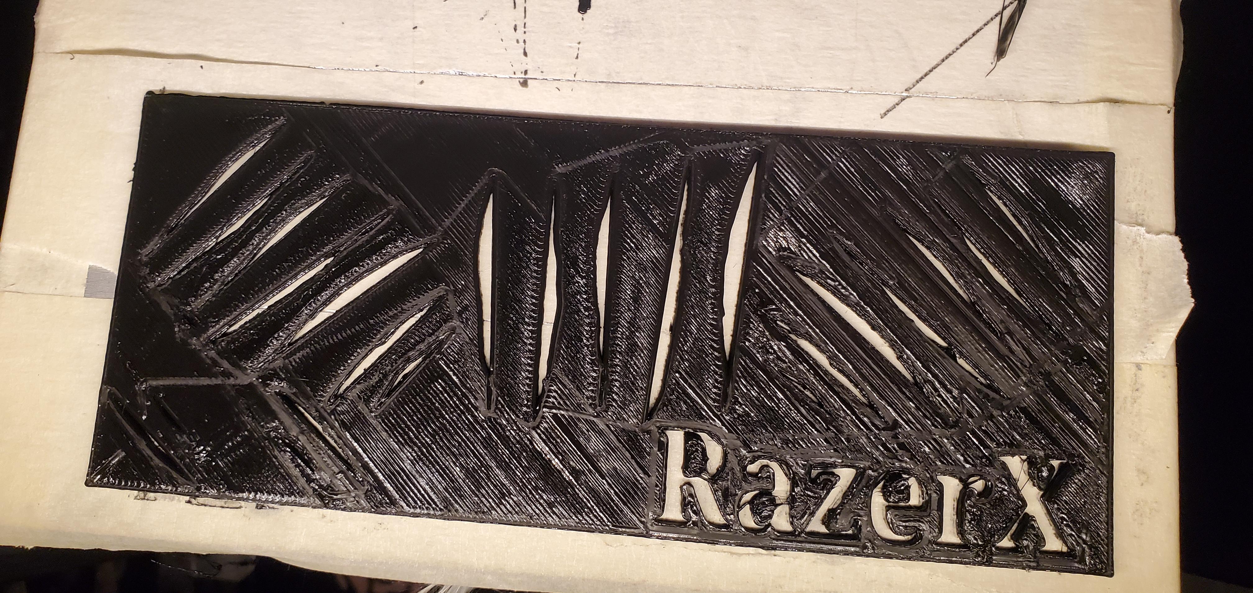
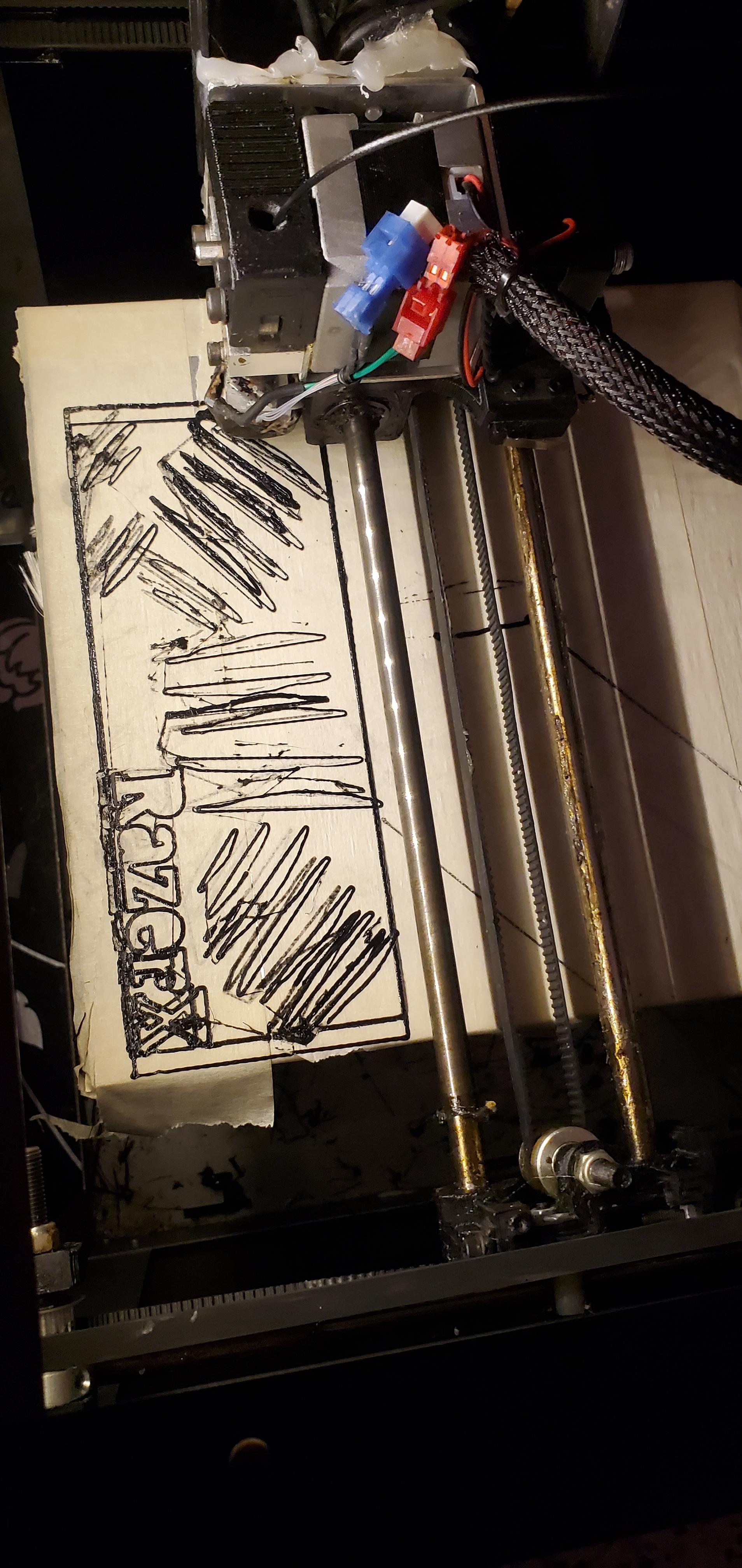
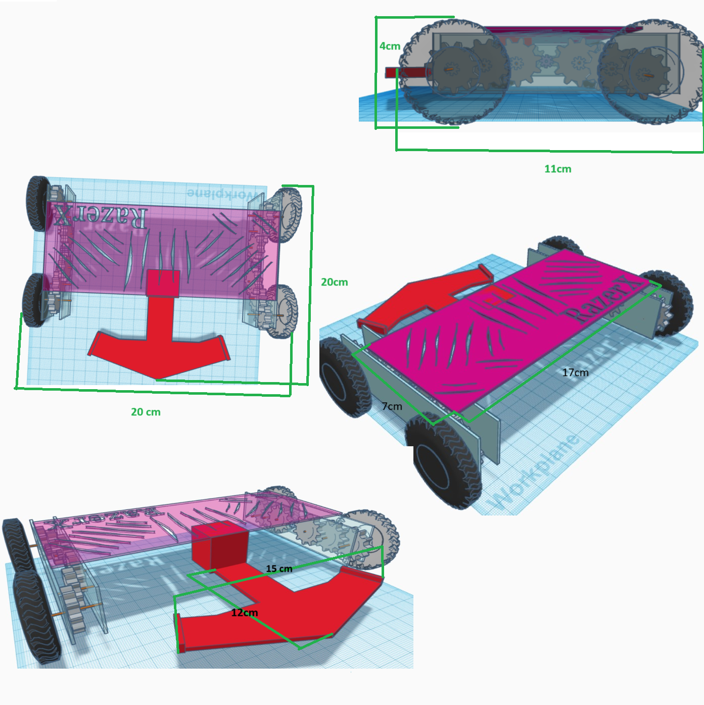
Download the 3D Model Files
Prepare the 3D Printer
- Check Printer Settings: Ensure your 3D printer is set up and ready with the appropriate filament (e.g., PLA or ABS).
- Preheat the Printer: Preheat the printer to the correct temperature for your chosen filament.
Load Files into Slicing Software
- Import the Models: Open your slicing software (e.g., Cura, PrusaSlicer) and import the body part files.
- Arrange the Models: Position the body parts optimally on the print bed to maximize space.
Configure Print Settings
- Set Layer Height: Choose a layer height that balances speed and detail (e.g., 0.2mm).
- Adjust Infill Density: Set the infill percentage (20-30%) based on your desired strength and material usage.
- Disable Supports: No supports needed.
Start 3D Printing
- Begin Printing: Once everything is set, start the printing process. Monitor the first few layers to ensure proper adhesion and print quality.
Assembling
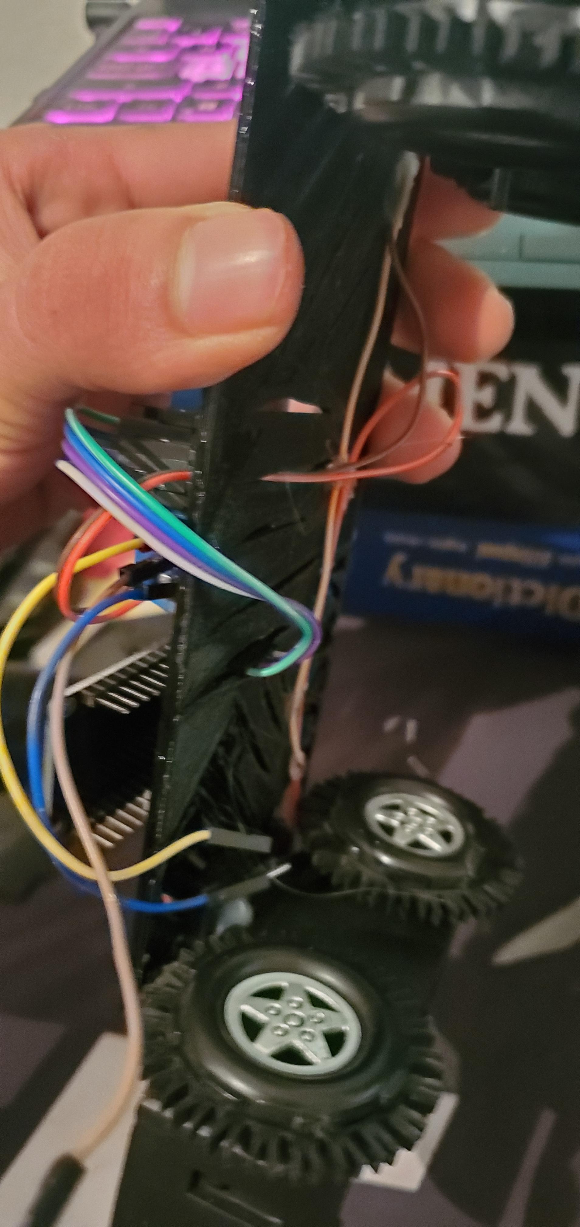
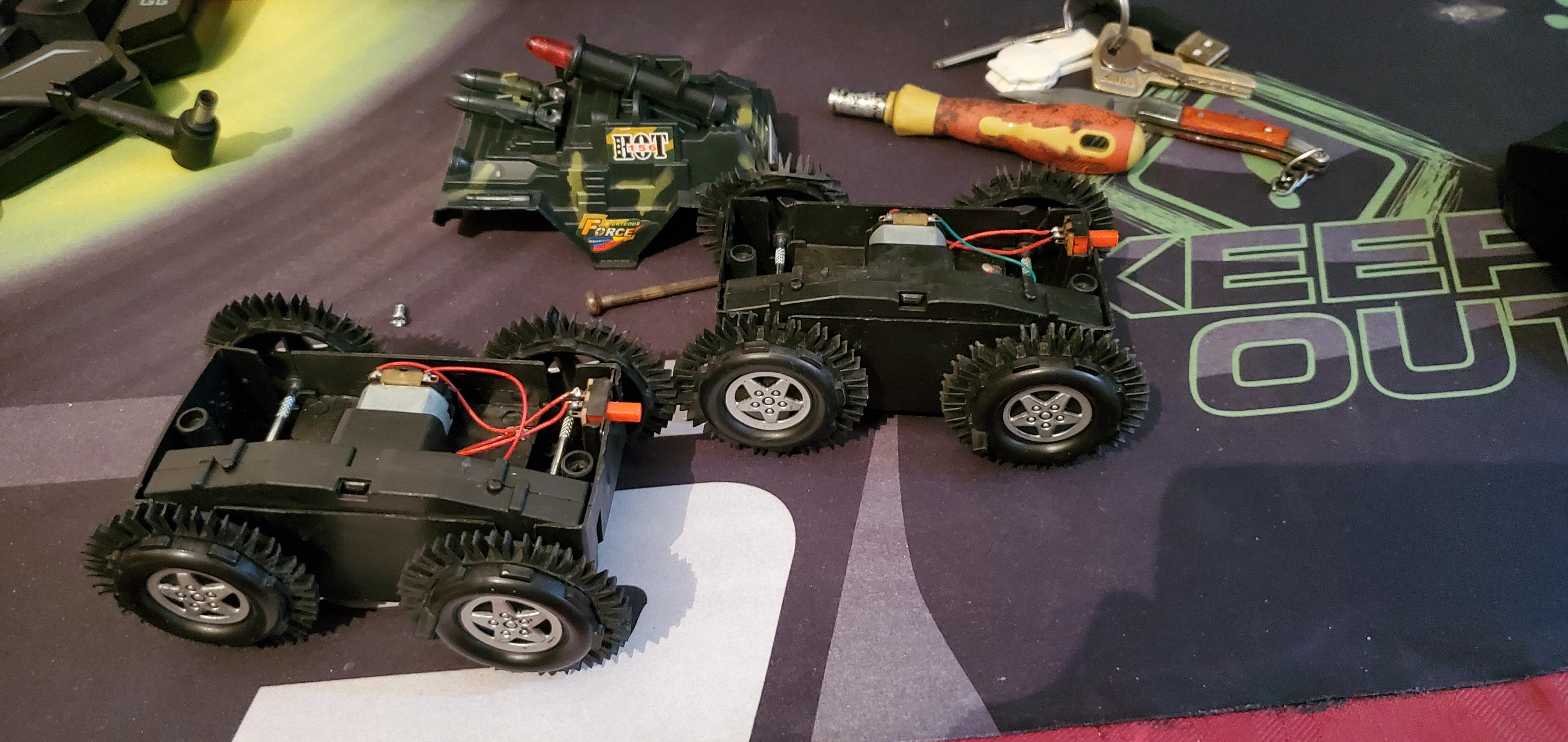
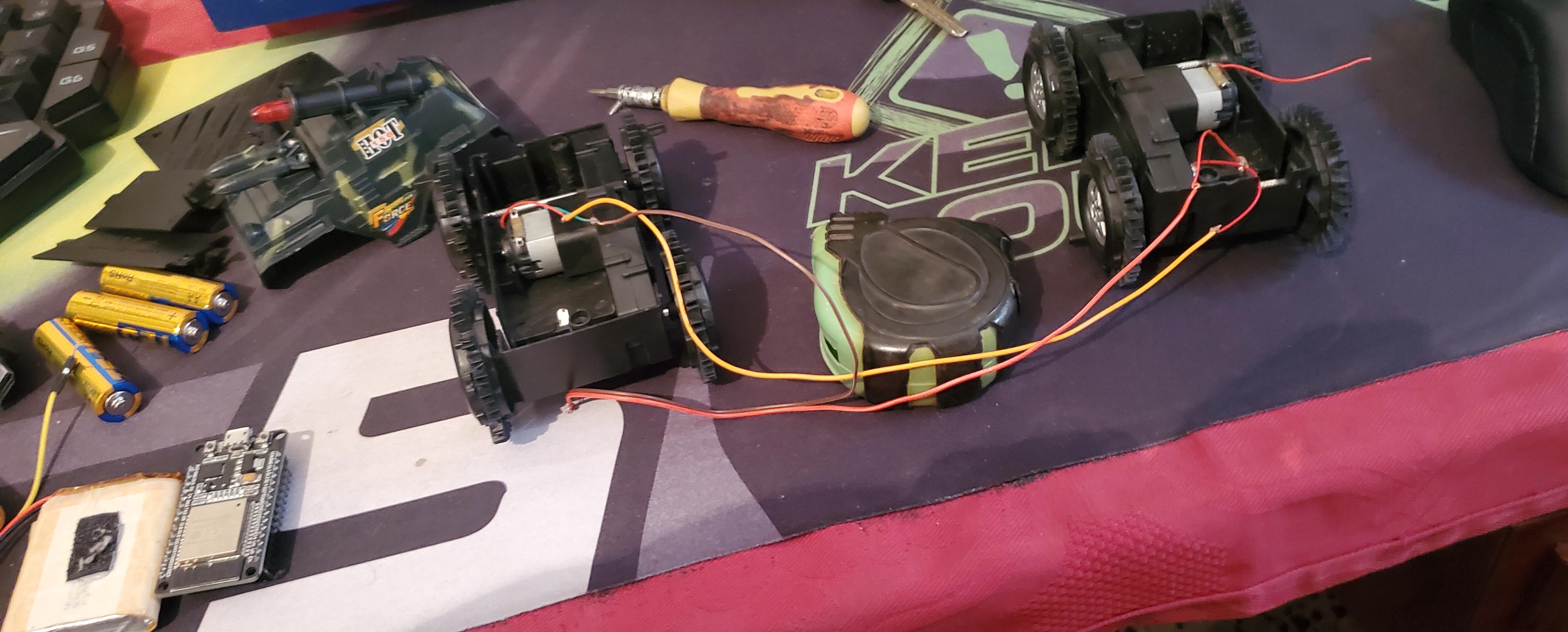
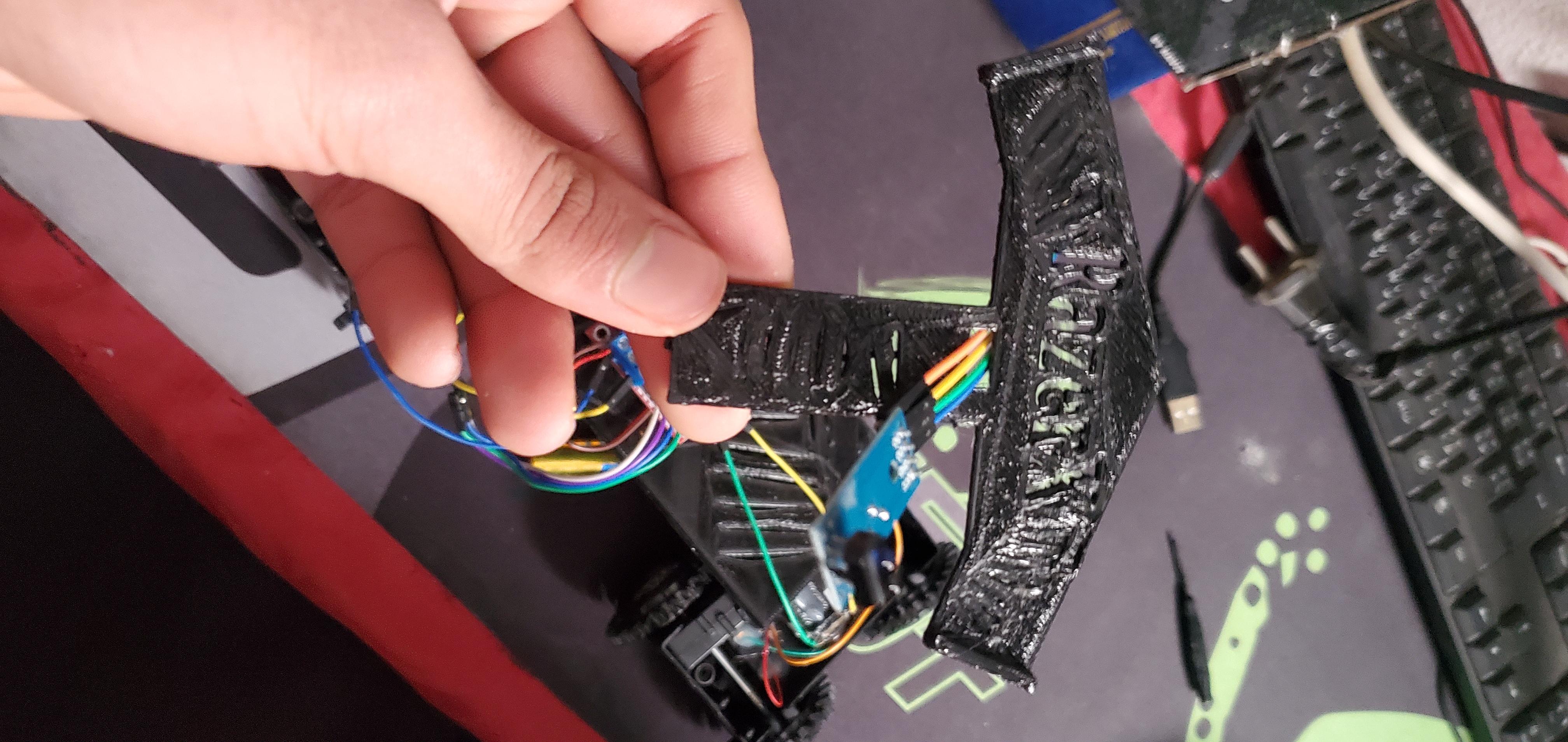
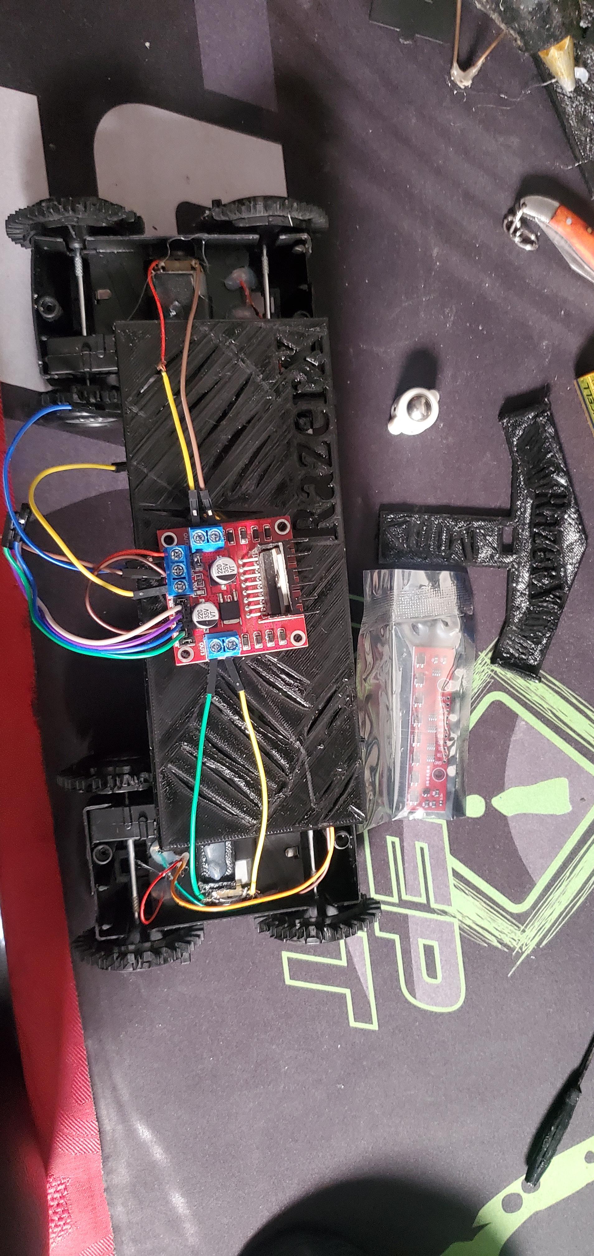
1. Disassemble the Toy:
- Extract Motors and Wheels: Begin by carefully taking apart the toy vehicle. Your goal is to retrieve the motors and wheels without damaging them.
- Tools: Use small screwdrivers or prying tools to disassemble the toy. If necessary, cut away plastic casings around the motors with a sharp blade or small saw, being careful not to damage the motors or their wiring.
- Label Wires: If the motors have attached wires, label them to ensure correct reconnection later.
2. Prepare the Main Body:
- Mark Motor Placement: Before attaching anything, mark the positions where the motors and wheels will be placed to ensure proper alignment.
3. Attach Motors and Wheels:
- Apply Glue: Apply hot glue generously around the motor mounts and press them onto the main body. Hold them in place until the glue sets. Ensure the motors are aligned so that the wheels will be parallel to each other.
- Wire Clearance: As you position the motors, ensure there is enough space for the wires to pass through the body without being pinched or strained. You may need to pass them in small notches or holes in the body to route the wires safely.
4. Attach the Front Section:
- Lower Front Placement: The front section of the robot, often housing the sensors, should be positioned slightly lower than the main body. This setup improves ground clearance, allowing the sensors to be closer to the surface and more effective at detecting lines.
- Use a Spacer: If needed, use an object or spacer between the front section and the main body to achieve the desired height. This could be a piece of plastic, wood
- Glue in Place: Secure the front section with hot glue, ensuring it is firmly attached and correctly angled. Double-check that the sensor mounting points are level and that the sensors will have an unobstructed view of the surface.
5. Sensor Mounting:
- Position Sensors: Place the sensors on the front section, arranging them in a straight line or slightly angled to improve detection accuracy on curves.
- Secure with Glue: Use hot glue to fix the sensors in place. Ensure they are securely attached but avoid excess glue that might interfere with their operation.
- Check Alignment: After gluing, check that all sensors are aligned and at an even height relative to the ground. Adjust if necessary before the glue sets.
6. Use the 3D Model as a Guide:
- Follow the 3D Model: use the 3D model of the robot as a reference during assembly. The model will help ensure that all components are positioned correctly and that the robot’s structure is balanced.
- Check Dimensions: Compare the physical assembly to the 3D model, especially focusing on the spacing and alignment of components like the motors, wheels, and sensors.
- Adjust as Needed: If the assembled robot differs from the 3D model, make necessary adjustments to align with the design specifications.
7. Final Checks and Adjustments:
- Test the Mechanisms: Before finalizing the assembly, manually rotate the wheels to ensure they spin freely and are not obstructed by the body or wiring.
- Wire Management: Route all wires neatly, securing them with small zip ties or additional glue if needed. This prevents them from getting tangled or caught in moving parts.
- Component Stability: Ensure all glued components are stable and secure. Reapply glue if any part feels loose.
8. Power and Electronics:
- Connect Electronics: Once the mechanical assembly is complete, connect the motors to the motor driver, attach the sensors to the control board, and connect the power supply.
By following these steps and using the 3D model as a guide, you'll ensure that your robot is well-constructed, with all components properly aligned and securely attached. This approach will contribute to the robot's performance in following lines efficiently.
Downloads
Wiring
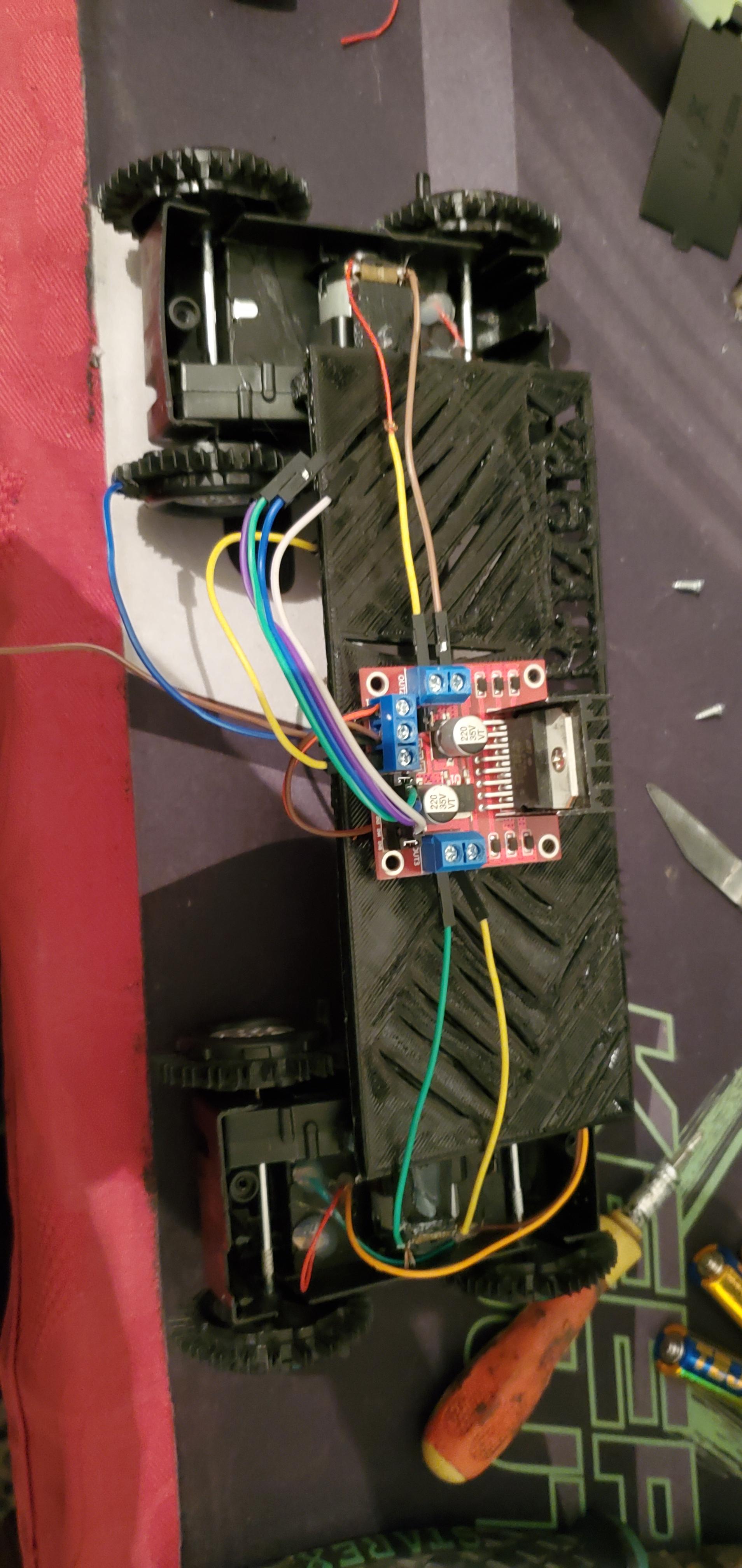
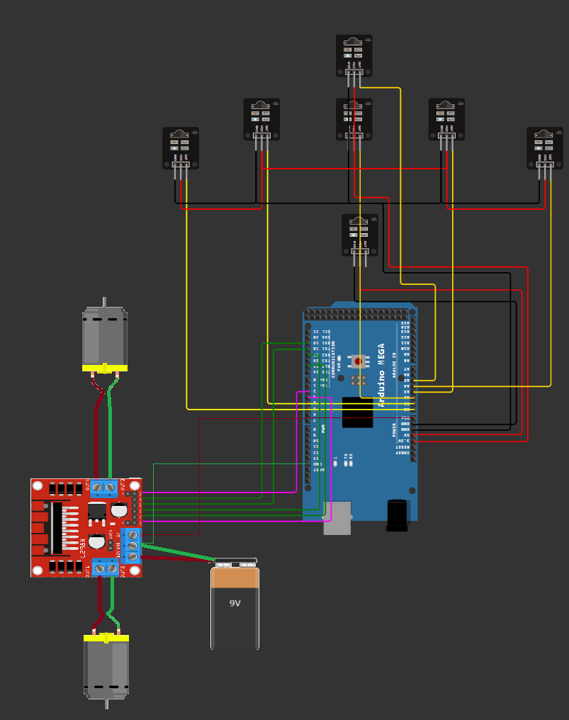
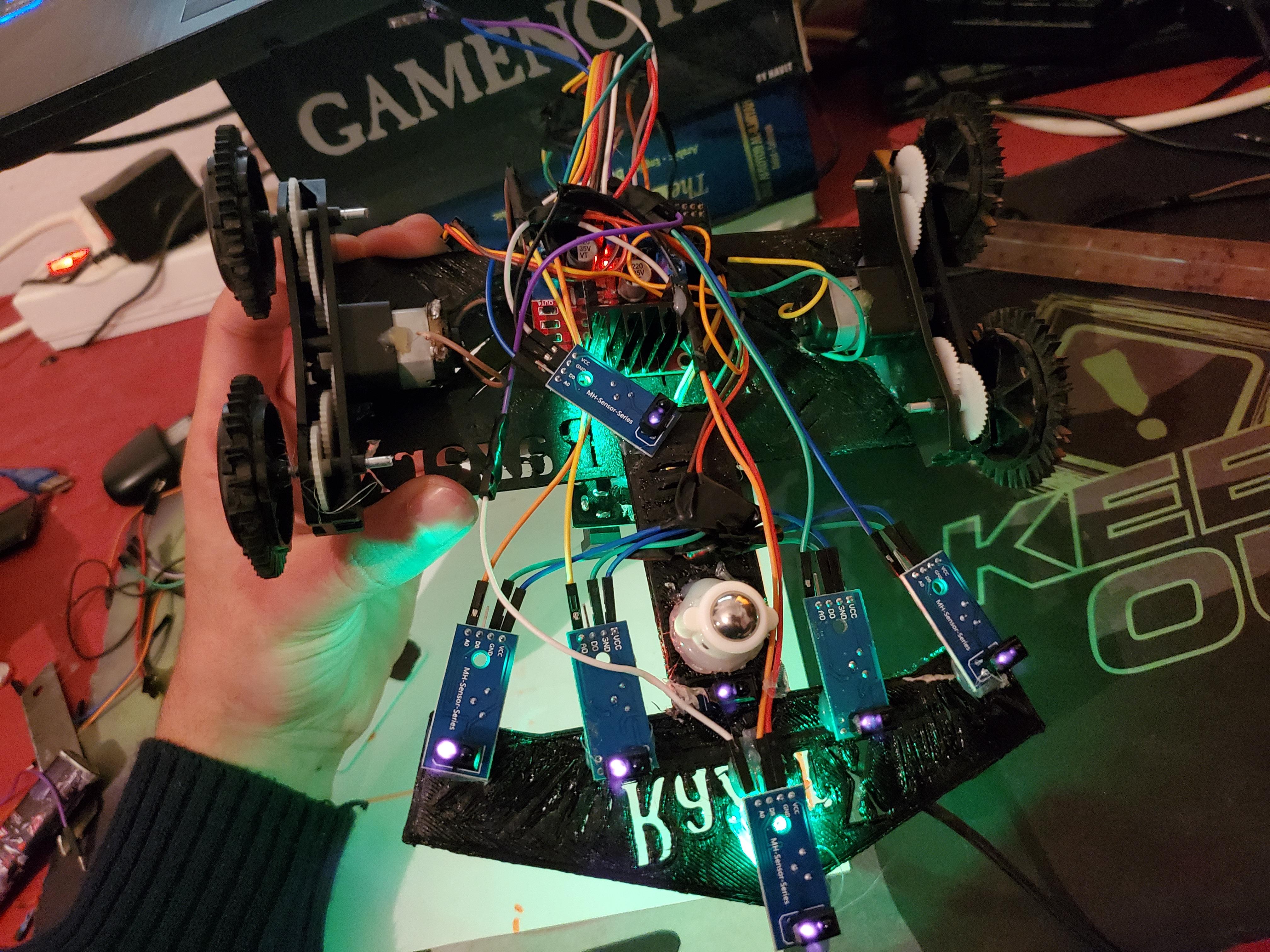
Wiring Steps:
1. Connect the Motor Driver to the Motors:
- Motor 1:
- Connect one terminal of Motor 1 to the OUT1 pin on the motor driver.
- Connect the other terminal of Motor 1 to the OUT2 pin on the motor driver.
- Motor 2:
- Connect one terminal of Motor 2 to the OUT3 pin on the motor driver.
- Connect the other terminal of Motor 2 to the OUT4 pin on the motor driver.
2. Connect the Motor Driver to the Arduino:
- Motor 1 Control (ENA and IN Pins):
- Connect ENA on the motor driver to pin 3 on the Arduino.
- Connect IN1 on the motor driver to pin 15 on the Arduino.
- Connect IN2 on the motor driver to pin 17 on the Arduino.
- Motor 2 Control (ENB and IN Pins):
- Connect ENB on the motor driver to pin 2 on the Arduino.
- Connect IN3 on the motor driver to pin 18 on the Arduino.
- Connect IN4 on the motor driver to pin 19 on the Arduino.
3. Power Connections:
- Battery:
- Connect the positive terminal of the 9V battery to the VCC pin on the motor driver.
- Connect the negative terminal of the 9V battery to the GND pin on the motor driver.
- Motor Driver Power:
- Connect the GND pin from the motor driver to the GND pin on the Arduino.
4. Connect the Line Sensors to the Arduino:
- Sensor Array (5 Sensors):
- Connect the OUT pin of each sensor to the following analog pins on the Arduino:
- Sensor 1 (far left): A0
- Sensor 2: A1
- Sensor 3 (center): A2
- Sensor 4: A3
- Sensor 5 (far right): A4
- Connect the VCC pin of each sensor to the 5V pin on the Arduino.
- Connect the GND pin of each sensor to the GND pin on the Arduino.
- Front Sensor:
- Connect the OUT pin of the front sensor to the A5 pin on the Arduino.
- Connect the VCC and GND pins as described for the sensor array.
- Back Sensor:
- Connect the OUT pin of the back sensor to the A6 pin on the Arduino.
- Connect the VCC and GND pins similarly.
5. Additional Digital Sensors:
- Right Side Sensor:
- Connect the OUT pin of the right sensor to the digital pin 24 on the Arduino.
- Left Side Sensor:
- Connect the OUT pin of the left sensor to the digital pin 22 on the Arduino.
- Power the sensors using the 5V and GND connections from the Arduino.
Final Checks:
- Ensure All Connections Are Secure: Double-check that each wire is properly connected and that the pins correspond to the correct assignment in the code.
- Test the Wiring: Before running the full code, verify that each motor responds to the control inputs and that the sensors are providing the expected signals.
Programing / Testing
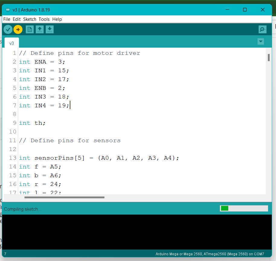
Code Explanation:
Setup and Initialization:
- Motor Control Pins: The motor driver is controlled through specific pins (ENA, IN1, IN2, ENB, IN3, IN4) assigned to the motors.
- Sensor Pins: Seven sensors are used to detect the line and surroundings (sensorPins[5], f, b, r, l).
- PID Constants: These values (Kp, Kd, Ki) are used to fine-tune the robot's movement, ensuring it follows the line accurately change it based on your robot behavior.
- Variables: Several variables are initialized to store sensor readings, PID error calculations, and motor speeds.
Calibration:
- The calibrate() function runs the robot in a circle to detect the minimum and maximum values of the sensors, determining the threshold for line detection.
Main Loop:
- Initial Calibration and Movement: Once, the robot calibrates itself, it makes a slight turn to align with the line and then starts moving forward.
- Sensor Readings: The robot continuously reads the sensors to determine the position of the line.
- PID Calculation: The error between the desired position and the actual position is calculated. The PID controller uses this error to adjust the speed of the motors (leftSpeed, rightSpeed) to keep the robot on the line.
- Movement Logic: Depending on sensor inputs:
- Forward: If the robot is on track, it moves forward.
- Turns: If the robot detects a turn, it adjusts its direction (left or right) accordingly.
- Special Cases: There are also provisions for handling complex situations, such as sharp turns or U-turns, but some are commented out.
Functions:
- Movement Functions (forward, turnRight, turnLeft): These control the motors based on the speed and direction needed.
- Error Calculation (calculateError): Computes the error by averaging sensor values to keep the robot centered on the line.
After uploading the code to your line-following robot, it's crucial to test and fine-tune the code based on how the robot behaves in real-world conditions.
1. Initial Testing:
Once the code is uploaded, observe the robot's behavior as it follows the line:
- Does the robot stay on the line? Check if the robot maintains a consistent path along the line.
- How smooth is the movement? Notice if the robot is jerky or if it smoothly follows the curve of the line.
- Speed vs. Control: Assess whether the robot can maintain its speed without losing track of the line.
2. Analyzing the Behavior:
Based on your observations, you can identify areas that might need adjustment:
- Overshooting or Undershooting Turns: If the robot overshoots or undershoots turns, the PID constants (Kp, Ki, Kd) may need to be adjusted.
- Oscillations: If the robot wobbles or oscillates while following a straight line, it could be due to the Kd value. Decreasing Kd might help reduce this effect.
- Slow Response: If the robot is too slow to correct its path, increasing Kp can make the robot more responsive.
- Integral Windup: If the robot’s corrections become too aggressive over time, you might need to adjust the integral limit or Ki value to prevent integral windup.
3. Fine-Tuning the PID Constants:
- Proportional Control (Kp): Start by adjusting Kp. This controls how aggressively the robot reacts to the error. If Kp is too high, the robot might oscillate or become unstable. If it's too low, the robot might be too sluggish.
- Integral Control (Ki): Fine-tune Ki to address any steady-state errors where the robot consistently drifts off the line. Be cautious, as too high of a Ki can cause the robot to overcorrect and oscillate.
- Derivative Control (Kd): Kd helps to dampen the oscillations by predicting future errors. Adjust this value if your robot is too jittery or oscillates when following curves.
4. Adjusting Threshold Values:
- During testing, if the robot struggles to detect the line correctly, revisit the threshold values set during the calibrate() function. You might need to run the calibration multiple times under different lighting conditions to ensure reliable detection.
5. Real-World Testing:
- Track Complexity: Test the robot on tracks with different complexities—sharp turns, intersections, or varying line widths. This will help ensure that the robot performs well in various scenarios.
- Speed Adjustments: If the robot performs well at lower speeds but struggles at higher speeds, you may need to adjust the motor speeds or further refine the PID constants.
- Environmental Factors: Test under different lighting conditions and surface textures to ensure the robot can consistently detect the line and adjust its path accordingly.
6. Iteration and Refinement:
- Document Changes: Keep track of the changes you make to the PID constants, thresholds, and other parameters. This will help you understand what adjustments lead to better performance.
- Iterate: Testing and tweaking should be an iterative process. After each adjustment, retest the robot and refine as necessary.
- Hardware Considerations: If the robot still struggles despite code adjustments, consider whether hardware changes (like repositioning sensors or adjusting motor power) might be necessary.
7. Final Optimization:
- Once the robot consistently follows the line with the desired speed and accuracy, you can finalize the code.
- Test the robot in different environments and with various track layouts to ensure it’s ready for competition.
8. Prepare for the Unexpected:
- Always expect the unexpected in competitions. Prepare to make quick adjustments if the track conditions differ from your testing environment.