Limit/Homing Switch for CNC3040 Laser Engraver With Endurance 10W Laser Module
by Yezariael75 in Workshop > Laser Cutting
4594 Views, 11 Favorites, 0 Comments
Limit/Homing Switch for CNC3040 Laser Engraver With Endurance 10W Laser Module
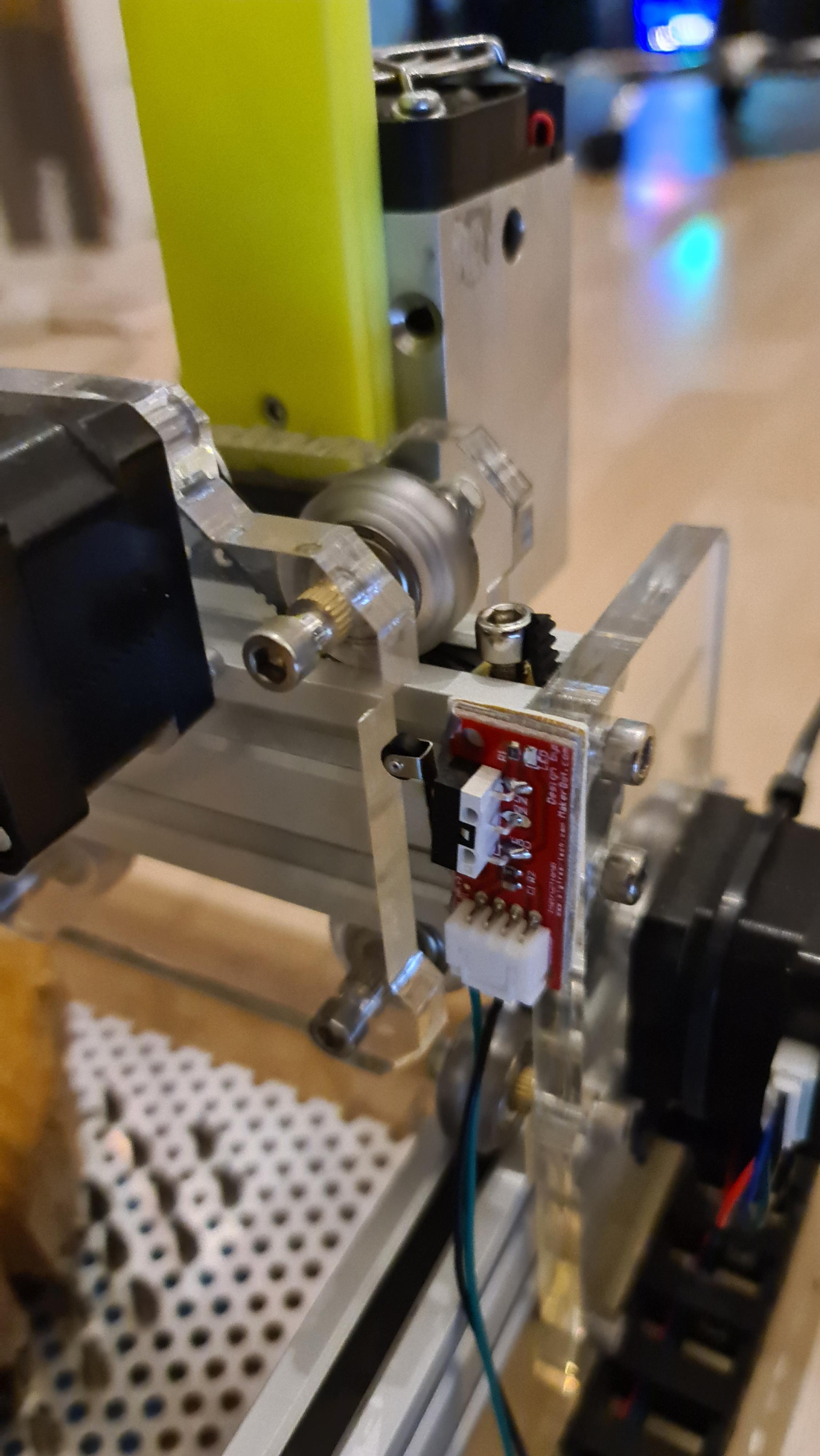
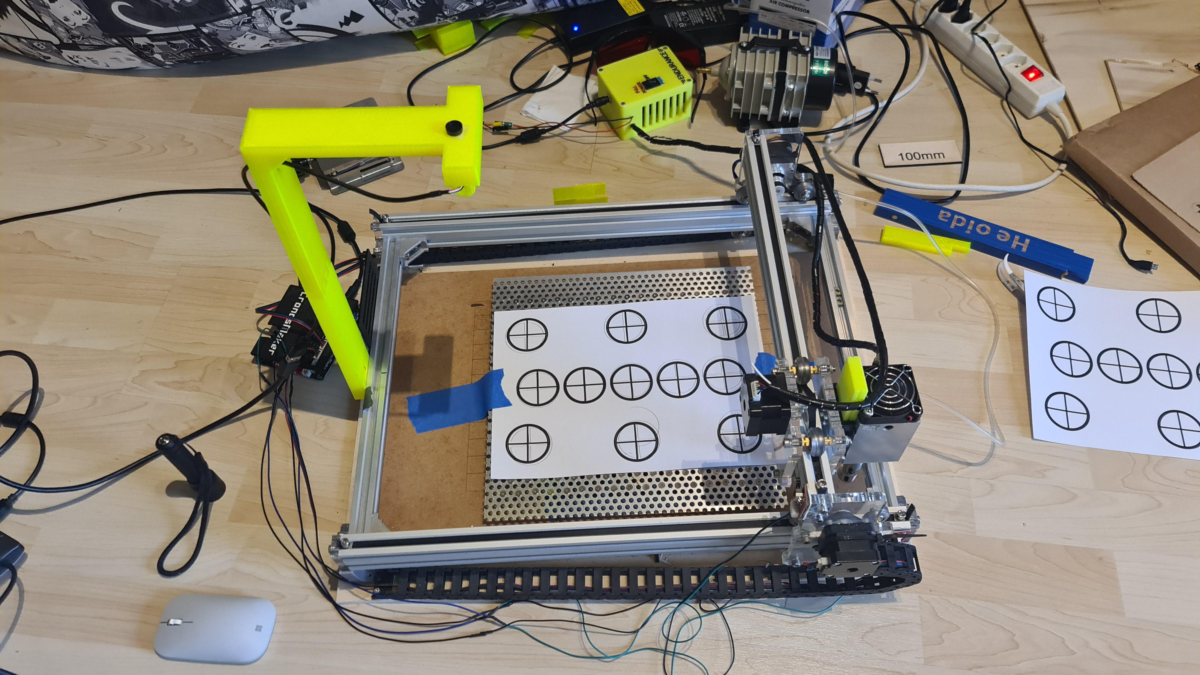
As I added last time a Lightburn camera to my laser engraver setup I wanted to have positioning as consistent as possible. Without hard limit switches this was not really possible. So I decided to add some limit switches to my laser engraving setup.
My setup:
- Endurance Lasers 10W laser head with the 3elements lens
- 3040 chinese CNC frame
- 160° chinese USB camera
- 3D printed camera stand from RowdyRoman
- Lightburn Software
- Microsoft Surface GO 2 Windows 10 Tablet
Downloads
Supplies
Basics:
- Laser engraver
- Lightburn software
- Lightburn camera
- Stand/holder for camera
- Notebook or desktop PC or Windows Tablet
For this instructable:
- Limit switches
- maybe some cables, soldering iron, heat shrink tubing
Choosing Limit Switches
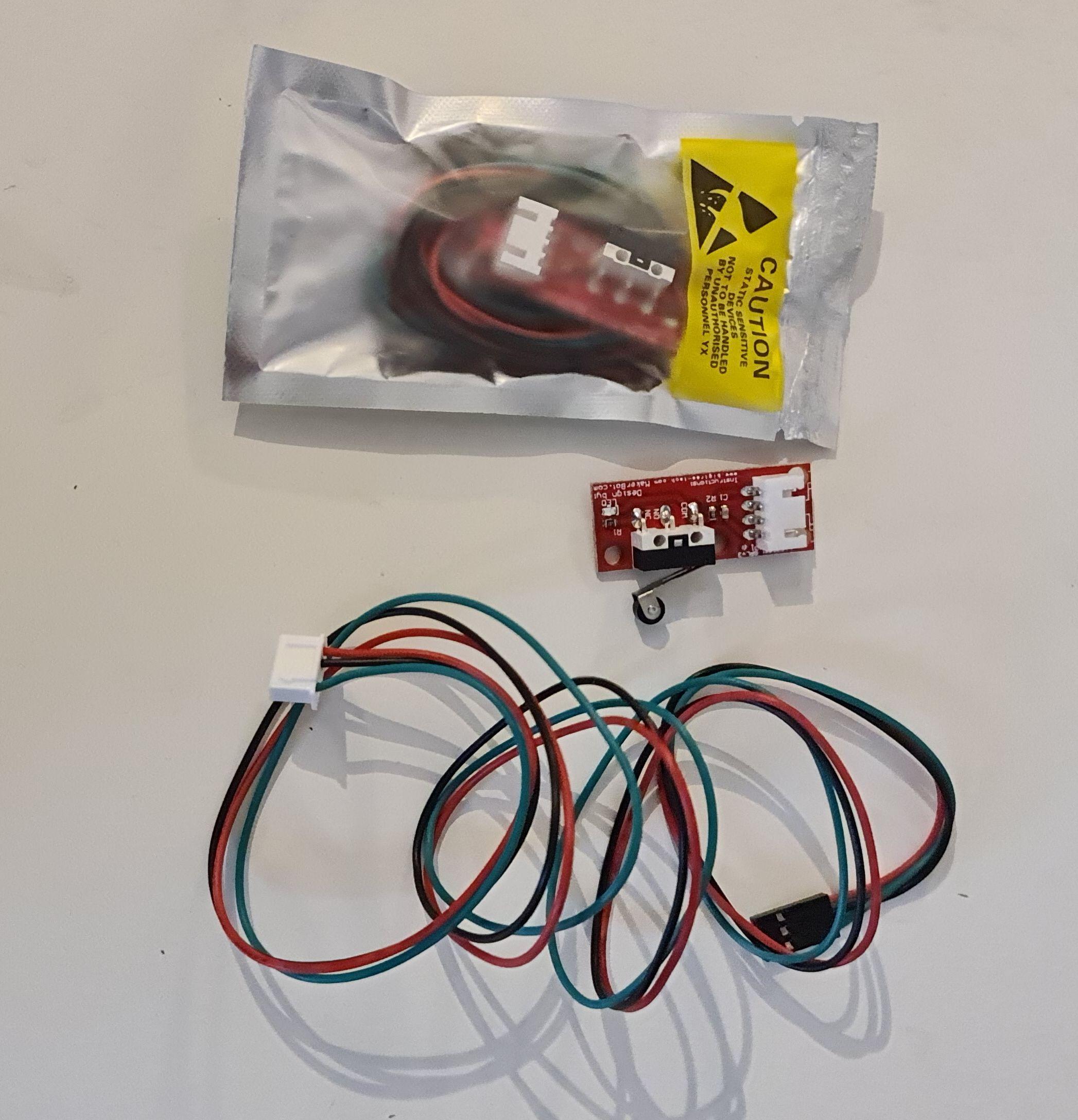
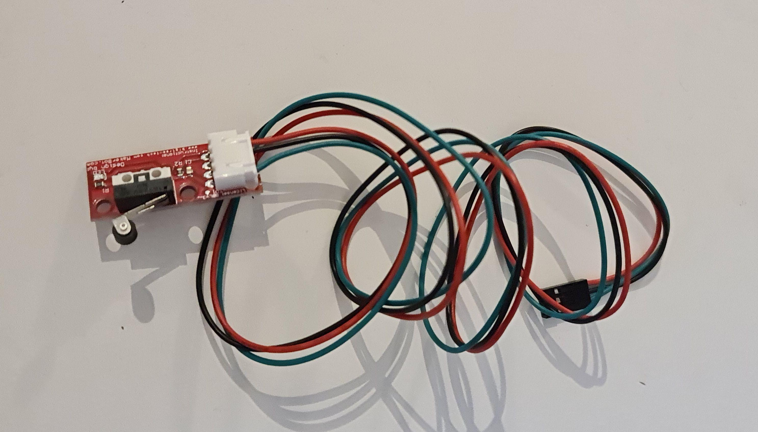
There are a lot of different limit switches available. For adding them directly to my Arduino nano board I choose some with pre-assembled electronics. You can choose some switches without electronics but most likely you will have to modify them and solder some resistors to them. There are other manuals out there which describe this.
Second, I had to choose the shape of the switch arms. I decided on some "roller" styles. Why? Just because I like them :) Every other style would be fine as well in my setup, yours may differ.
Preparing Limit Switches
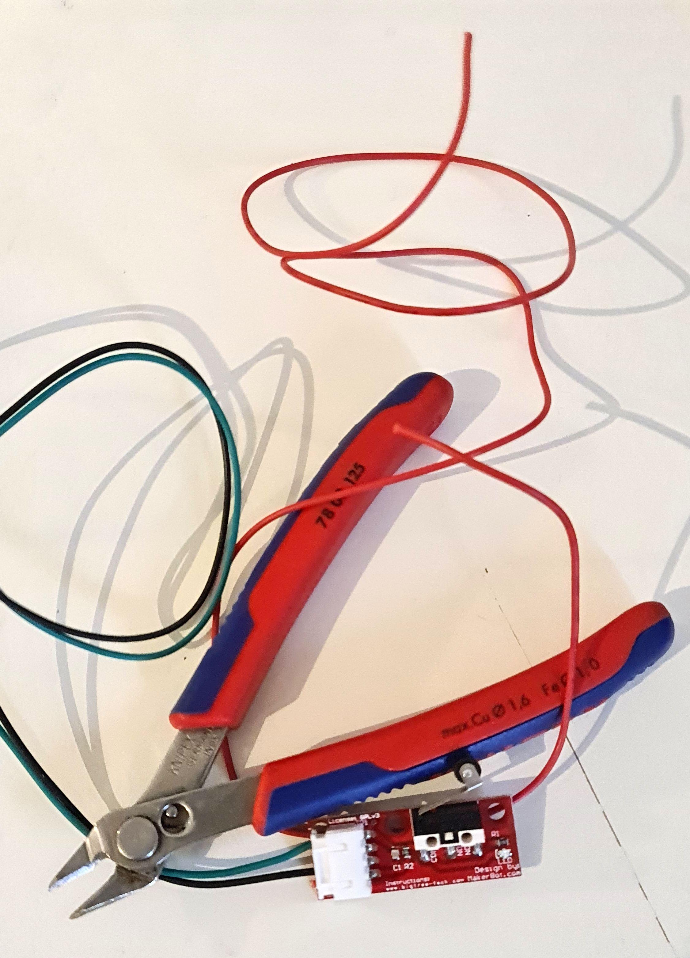
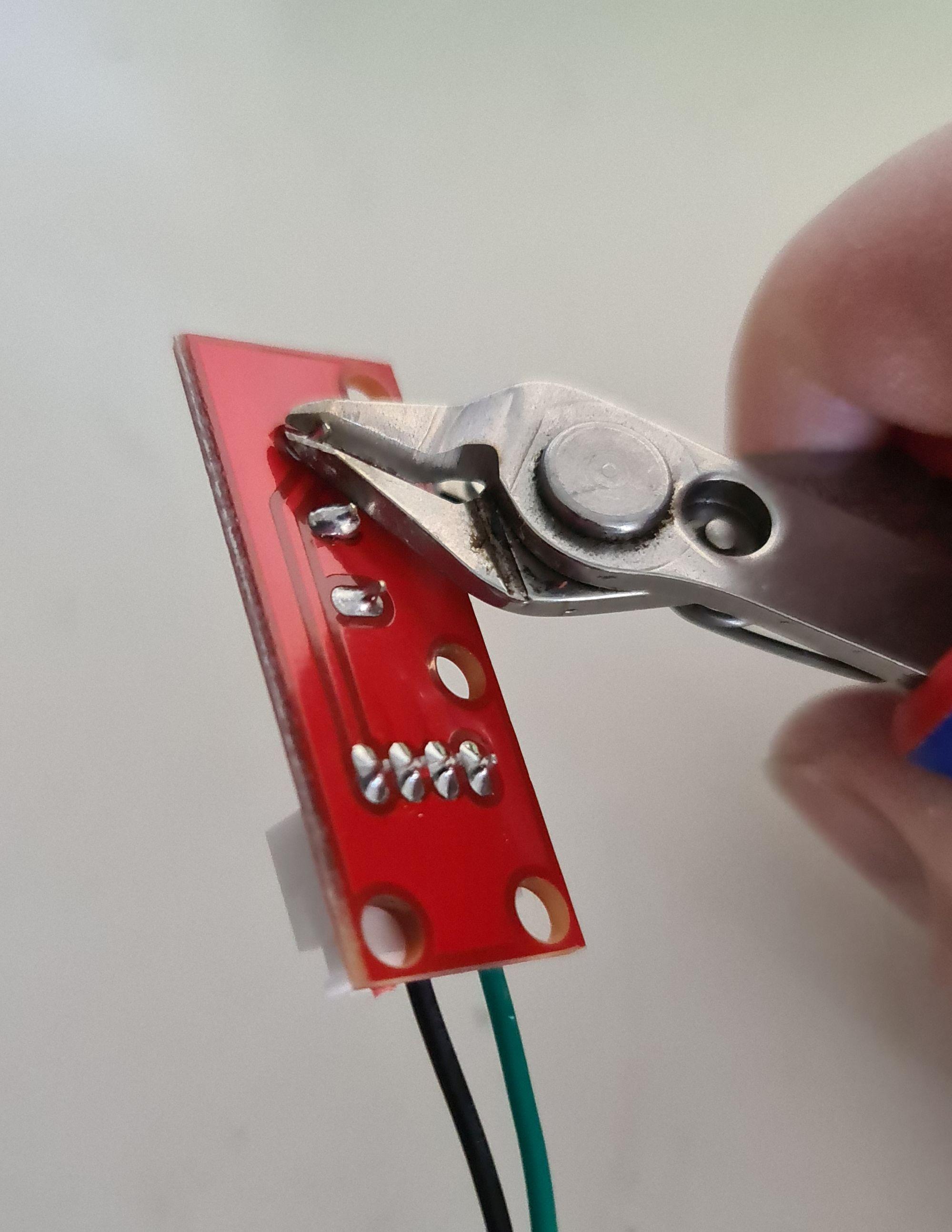
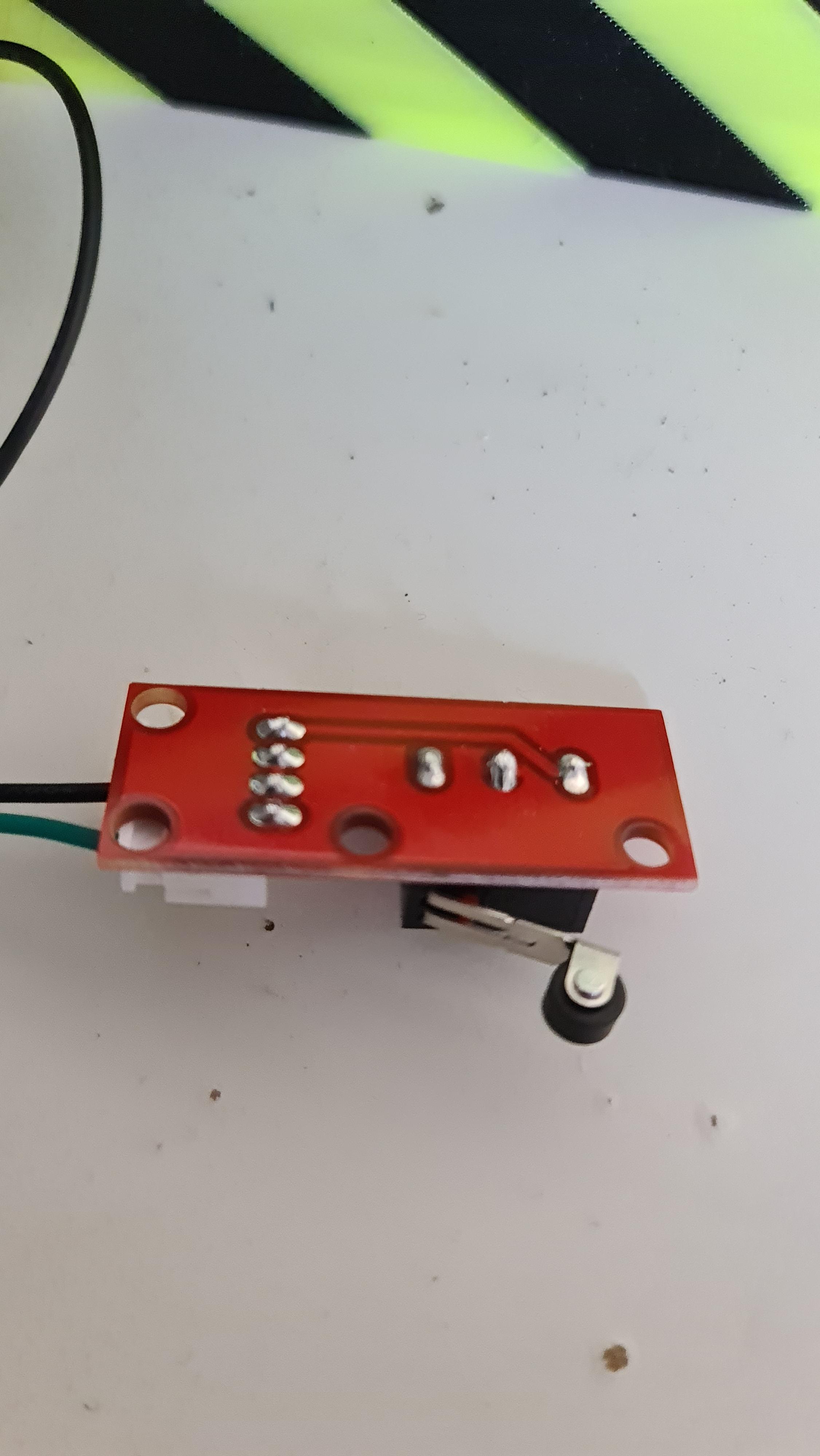
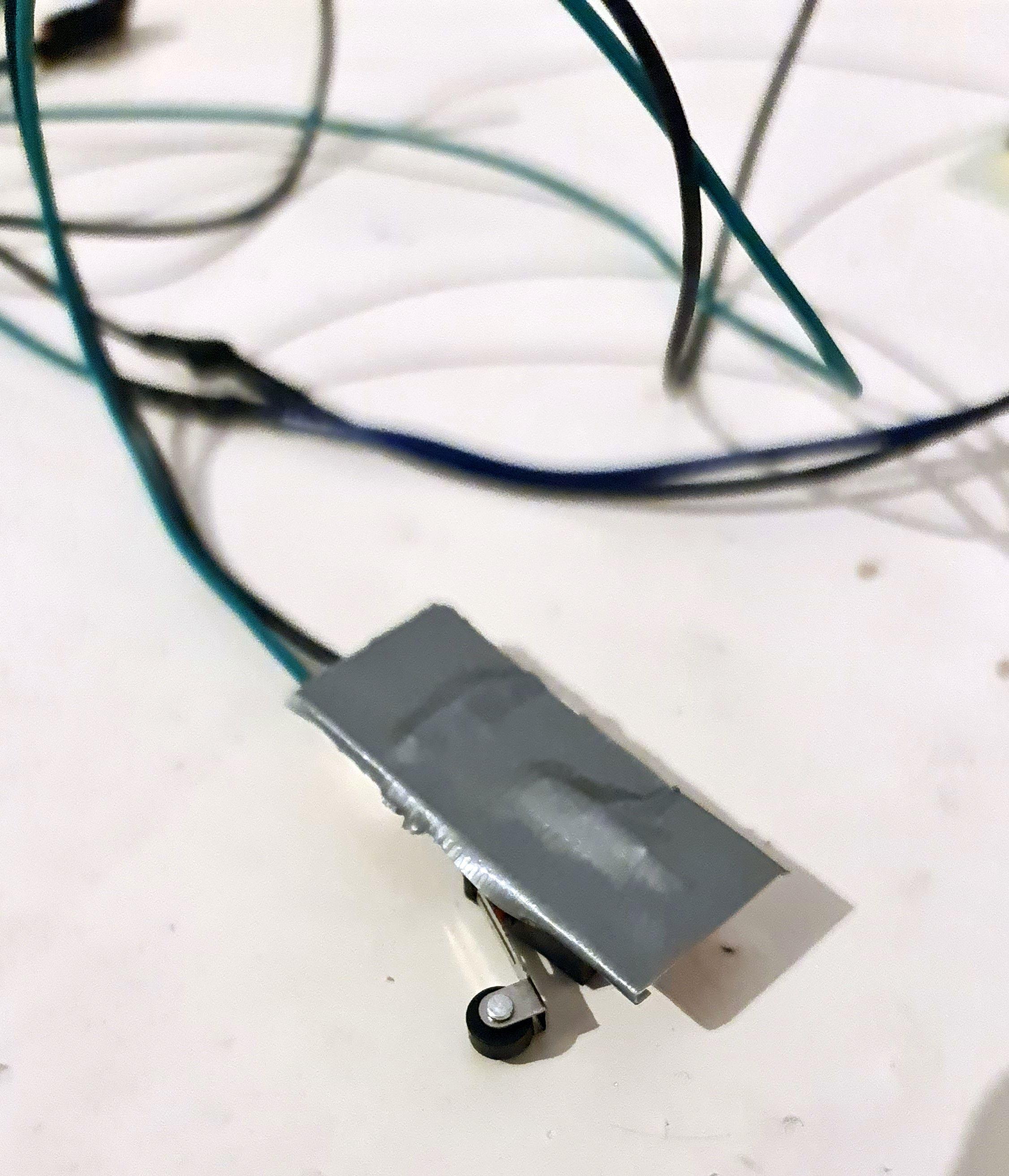
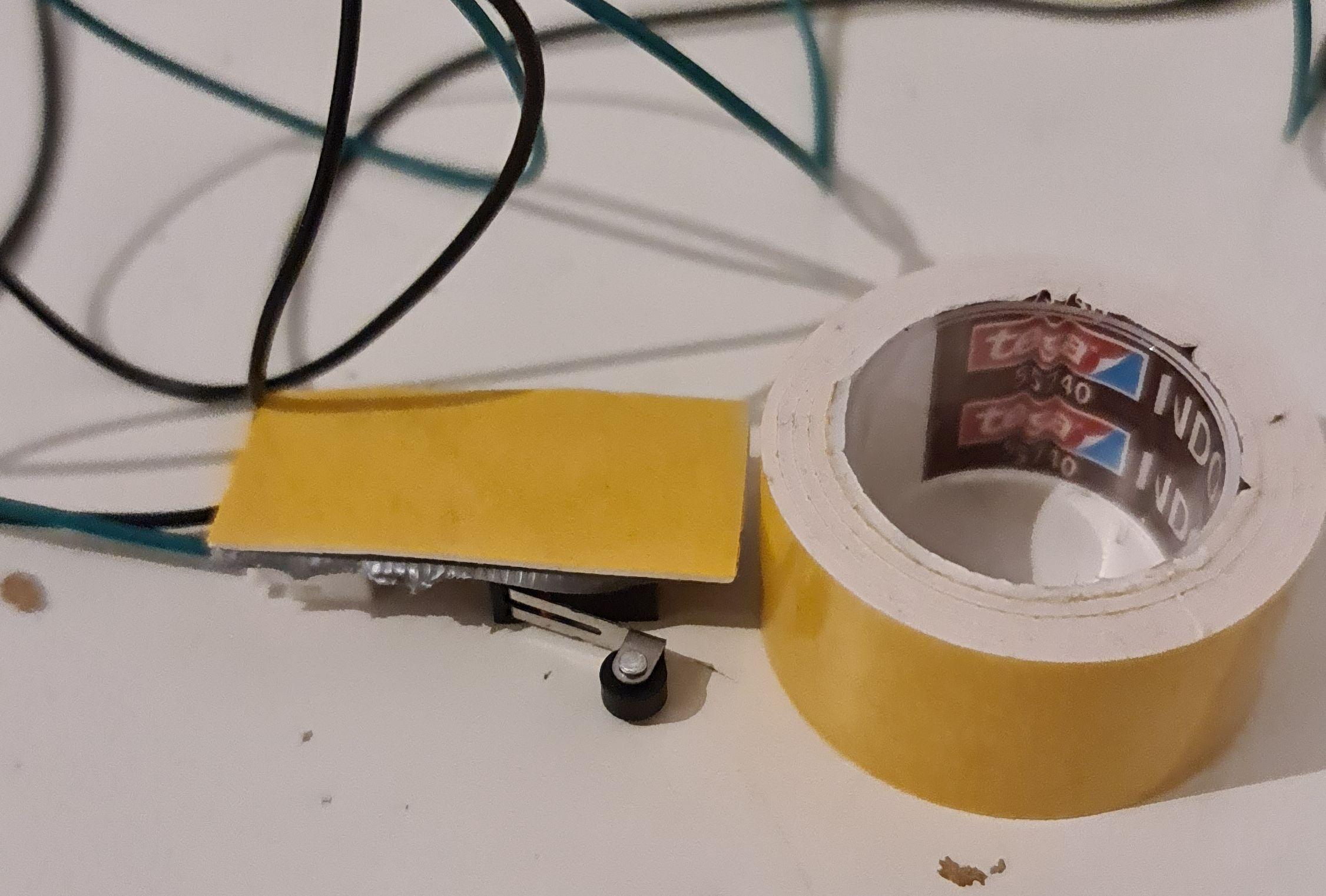
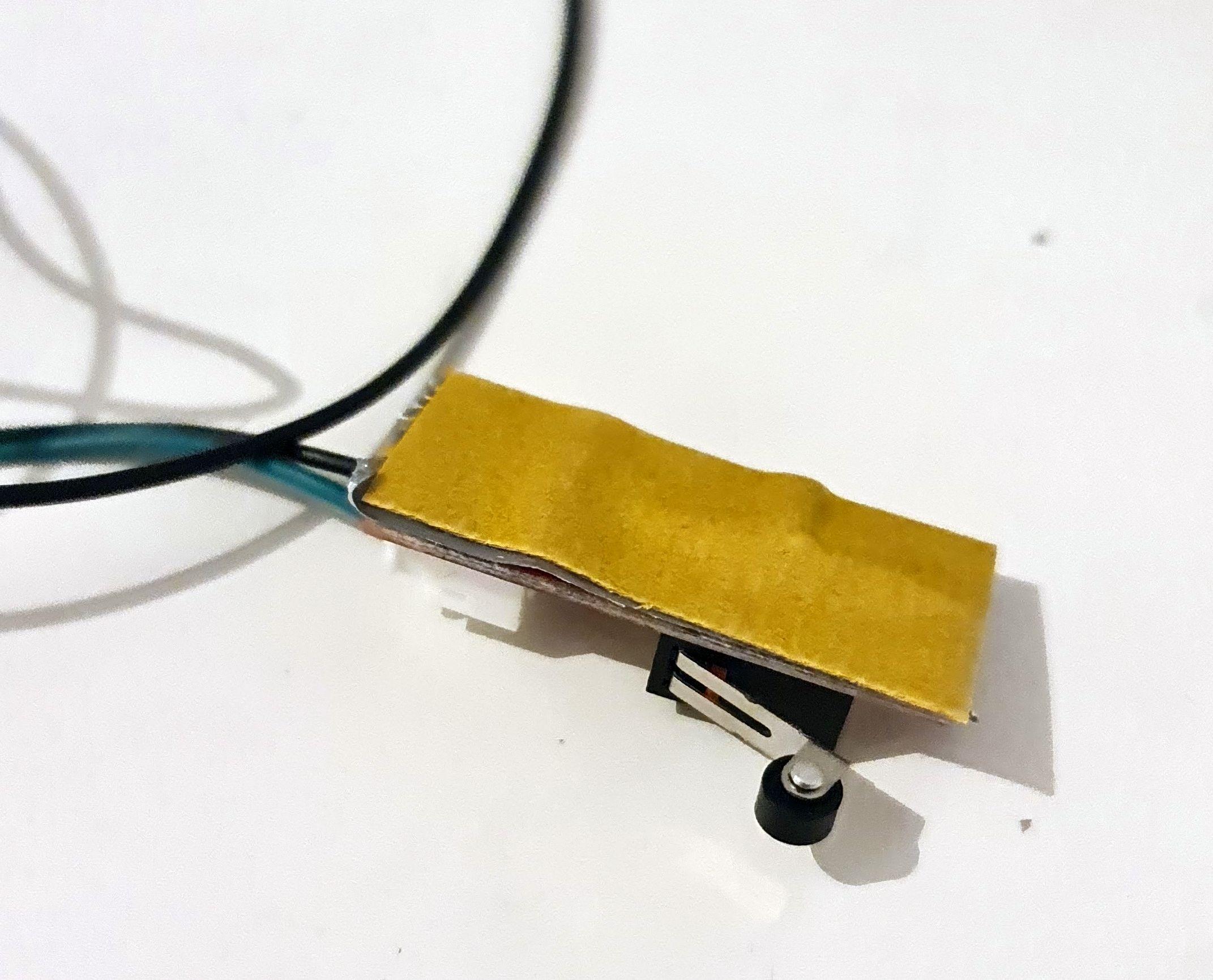
As LaserGRBL firmware on Arduino laser engraving boards is comming from a CNC background, homing is on the top right. As I have a 3D printing background I want to have homing on the front left. As the provided cables were to short I had to lengthen them.
For this I just cut the cables and soldered some more cable to them, using heat shrink tubes to make sure nothing can produce a short. As the red cable is not needed (it's for the LEDs) I cut them off.
I want it as simple as possible, so I decided to mount the switches with some double sided tape. As the switches have some long soldering joints which possibly could be a problem I just cut them carefully off. I added some duct tape to proctet the joints and afterwards some thick double sided tape to them.
Settings for LaserGRBL Firmware
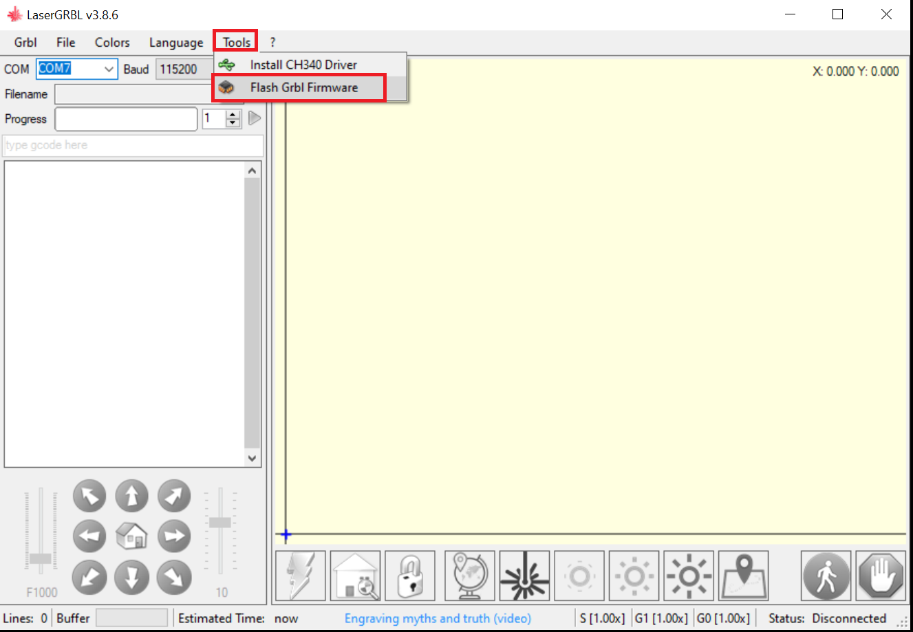
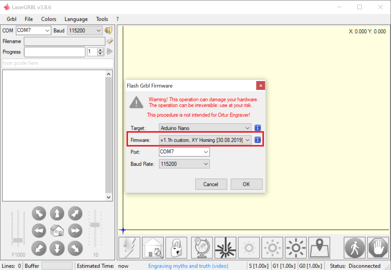
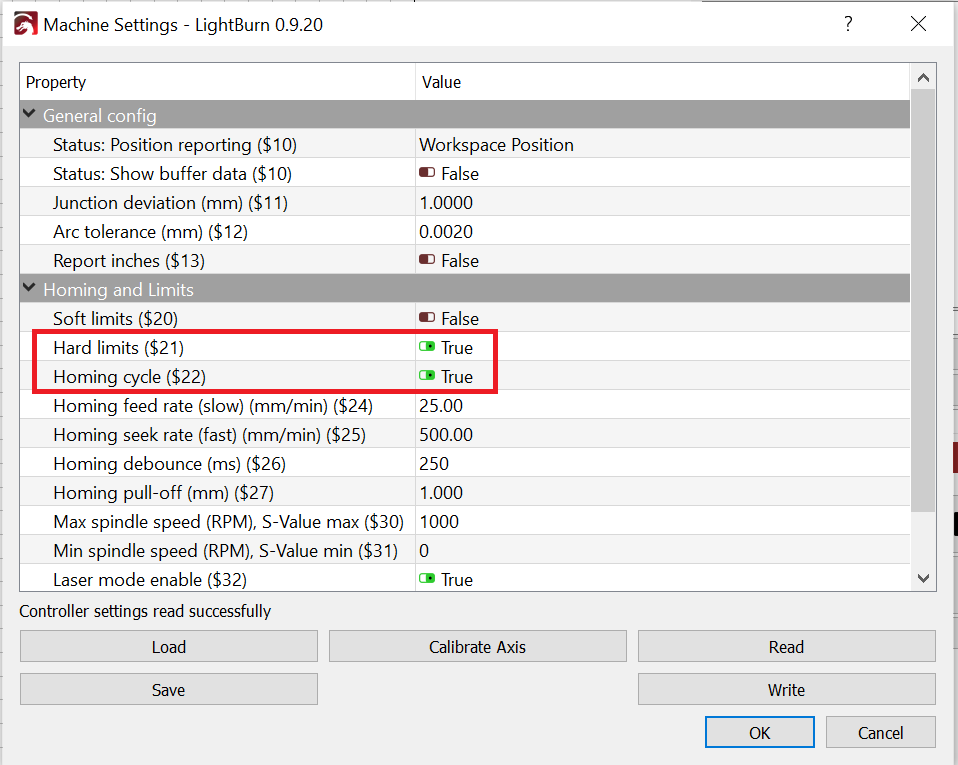
I have a 2 axis CNC frame without motorized Z axis. So in the first step I had to flash a new LaserGRBL firmware to the Arduino board. Luckily there is one available directly from LaserGRBL with the name "XY Homing". If you do not use this firmware it wants to home Z axis as a first step and you will run into an error message because this is not possible.
After that I had to change some Machine Settings in Lightburn to activate homing (you can do the same in LaserGRBL software).
Set $21 Hard Limits to TRUE and $22 Homing cycle to TRUE. If you like you can configure Lightburn to do a homing cycle on connection.
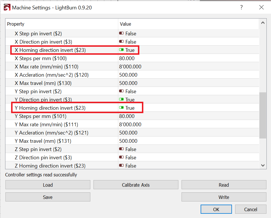
Second, to have home position on front left I inverted homing directions for X and Y axis with setting $23 to TRUE.
Connecting Switches to Board
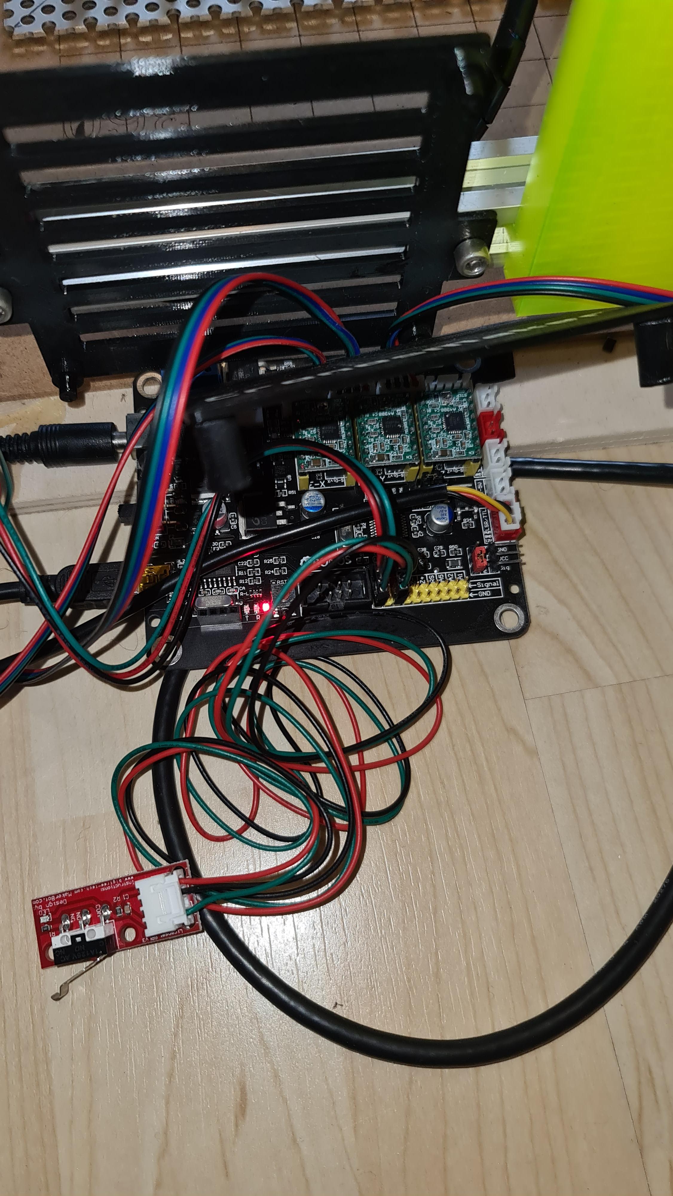
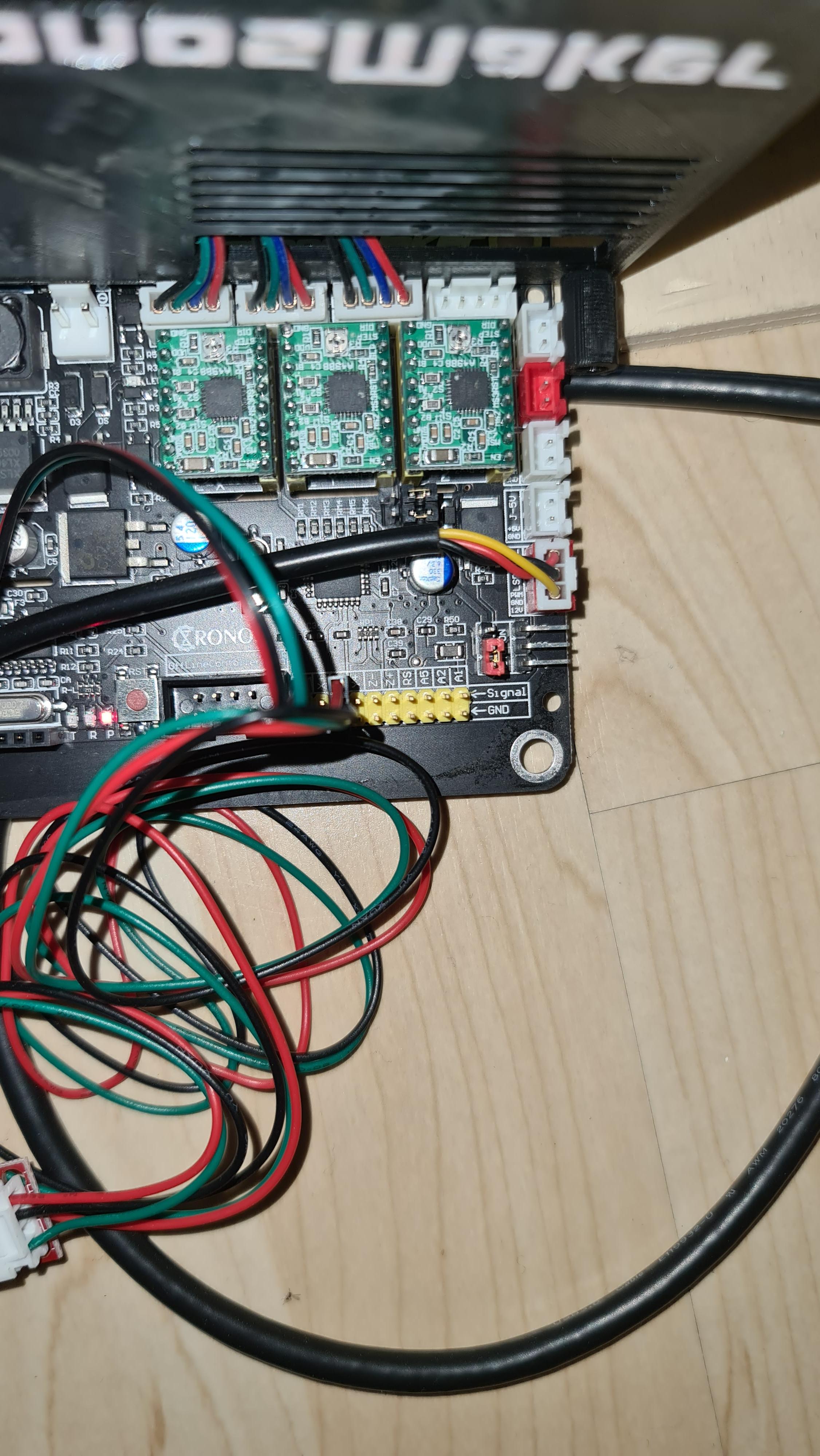
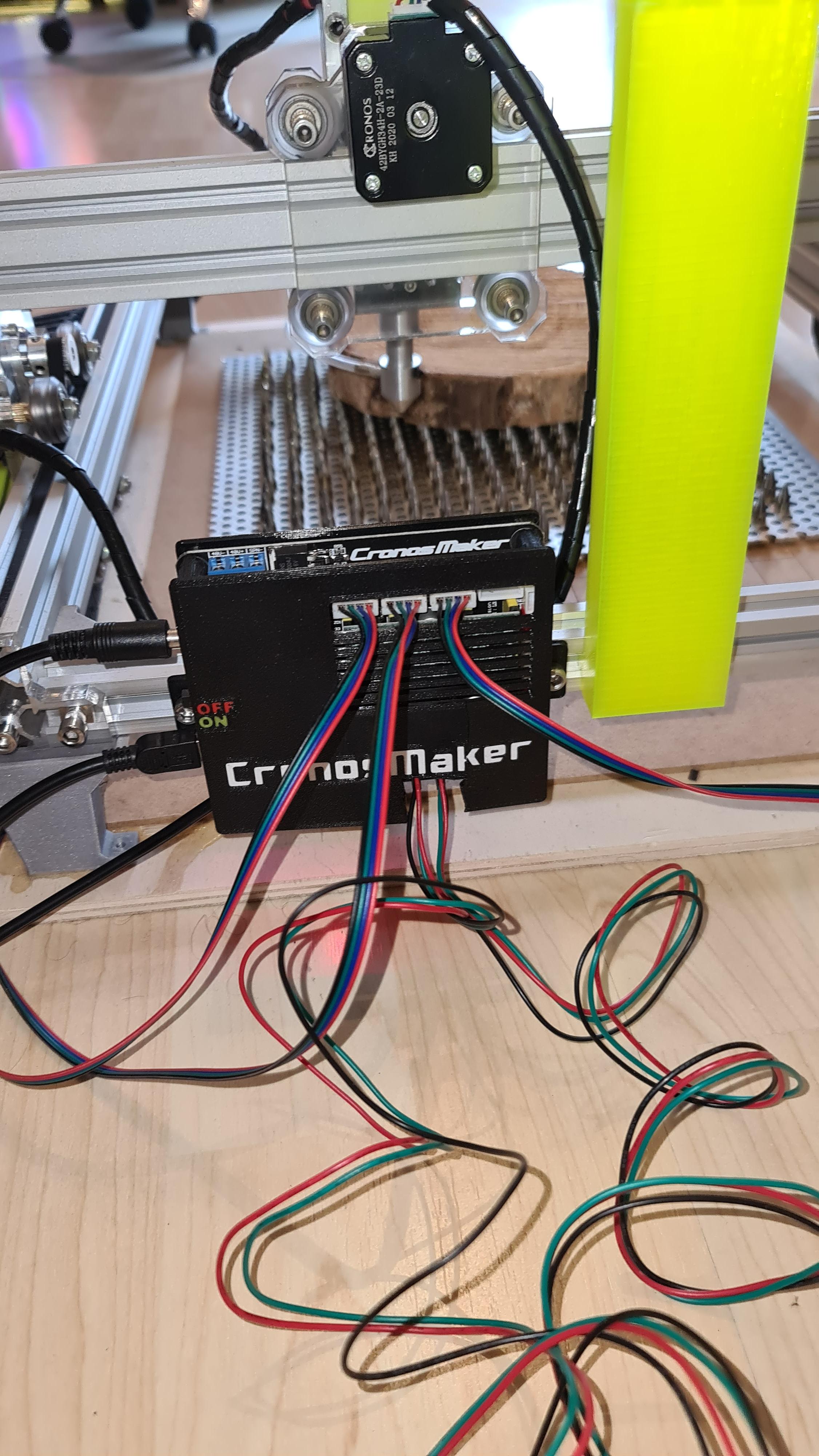
Have a look at your Arduino board where to connect your homing switches. Connect them to X- and Y-. Maybe you have to test which way they work best, the software will you not tell this. There is no risk of producing a short so just do it.
After connecting the switches you can test them if you push by hand. You should get a message in Lightburn console. To test homing by hand you will have to push every switch two or three times, as this is done in homing cycle as well (see my videos).
Downloads
Mounting Switches to Laser Frame
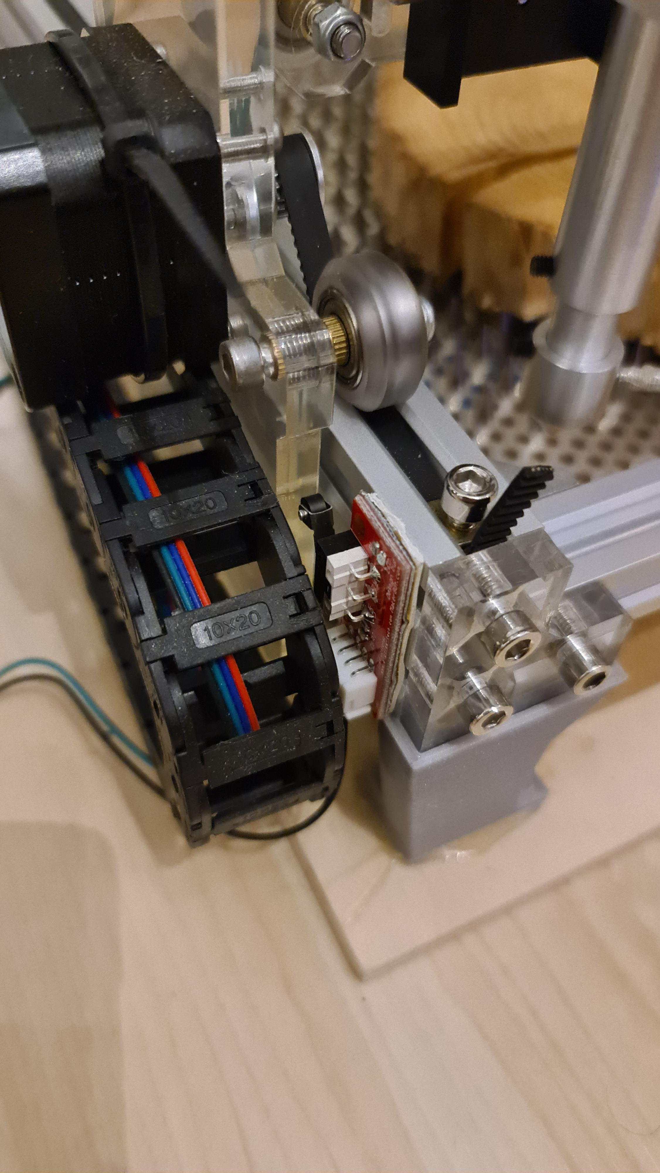
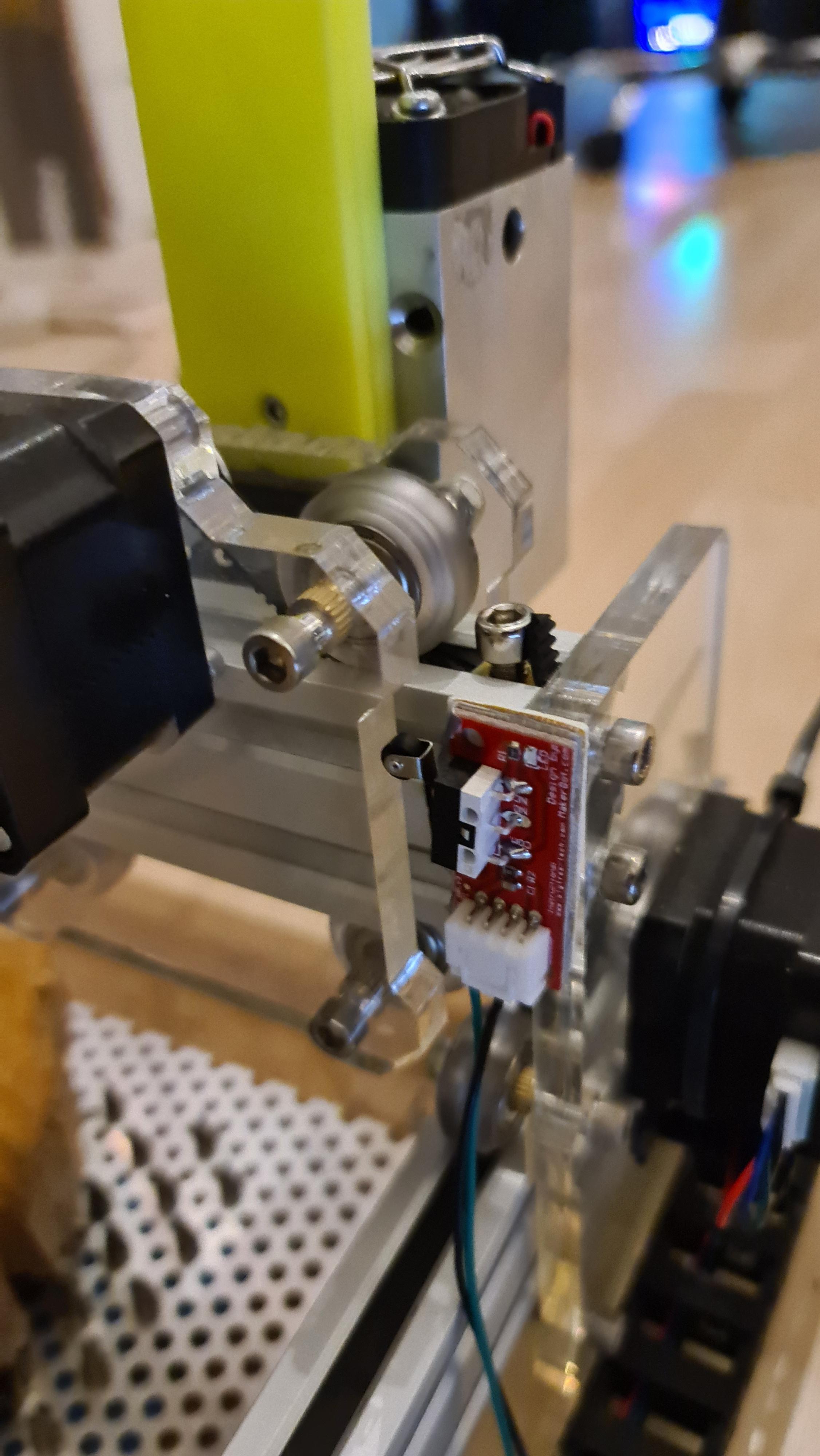
Have a look at your setup and find the best place to mount the switches. Make sure everything works fine and nothing is hitting against anything. If you are sure use the double sided tape to mount the switches.
Now you can click the homing button in Lightburn software and your laser head will move until it reaches the switches and stop there - everytime at the exact same place.
Finishinig / Testing Lightburn Camera
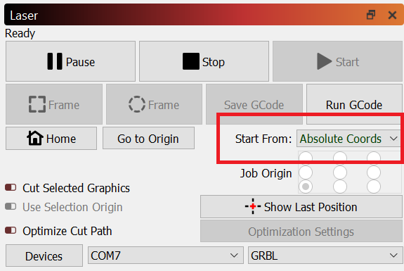
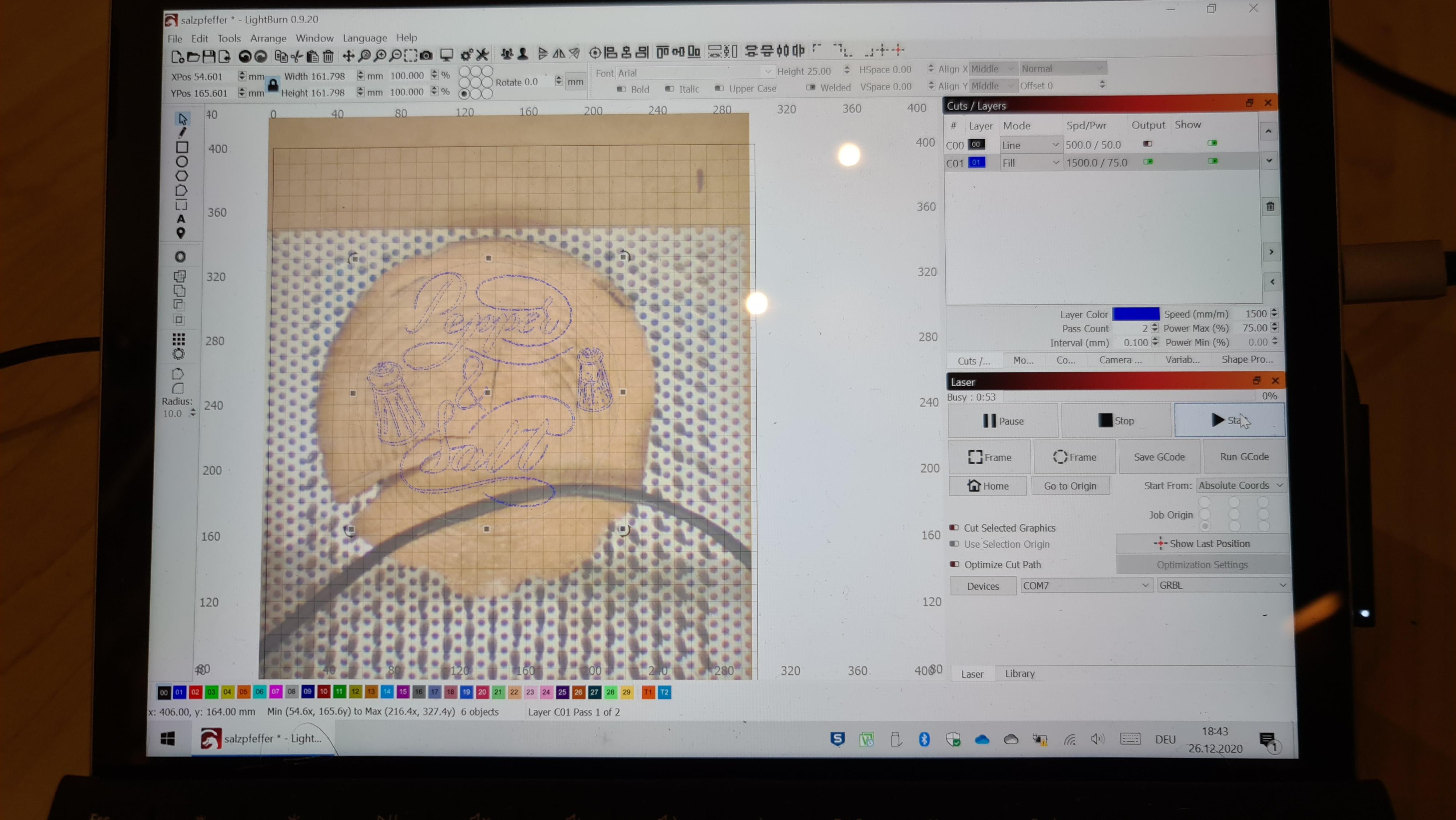

To make use of the Lightburn camera you must re-align it. Choose "absolute coordinates" in Lightburn, home your laser head and choose "Tools/Calibrate Camera Alignment". You can find this in my other instructable.
Then you can Update Overlay on the camera tab and position your design exactly over your workpiece. Now start the engraving and you're done :)