Lightworks
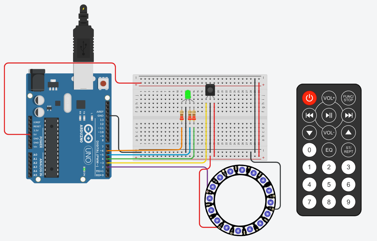
This is a DIY light ring that you could put in your car, under your bed, or wherever you please for it provides the best decor. It comes in handy with an IR remote with which you can choose between 9 colours for the ring and 3 colours for the led. It takes only a few steps to make. So, LET'S GET STARTED!!!
Supplies
So you are going to need a couple of things:
1. A breadboard
2. Arduino Micro-Controller
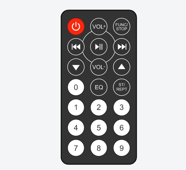
3. An IR remote
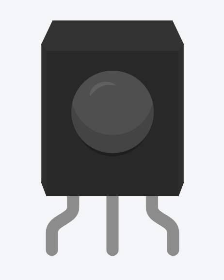
4. An IR receiver
5. An RGB LED
6. 3 (220 Ω resistors)
7. A Neo Pixel Ring
8. Jumper wires
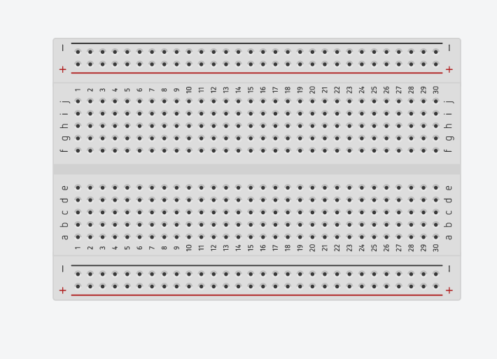
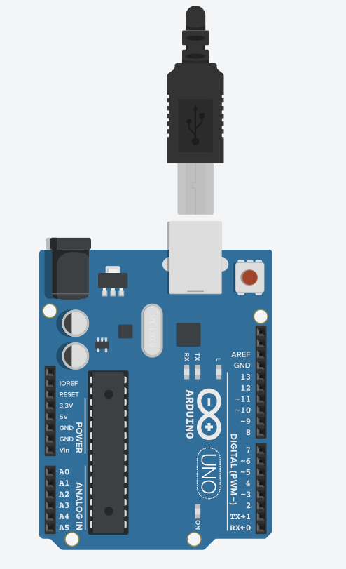
Images of all are given below in order.
Bread Board, Arduino and Cables
.png)
.png)
.png)
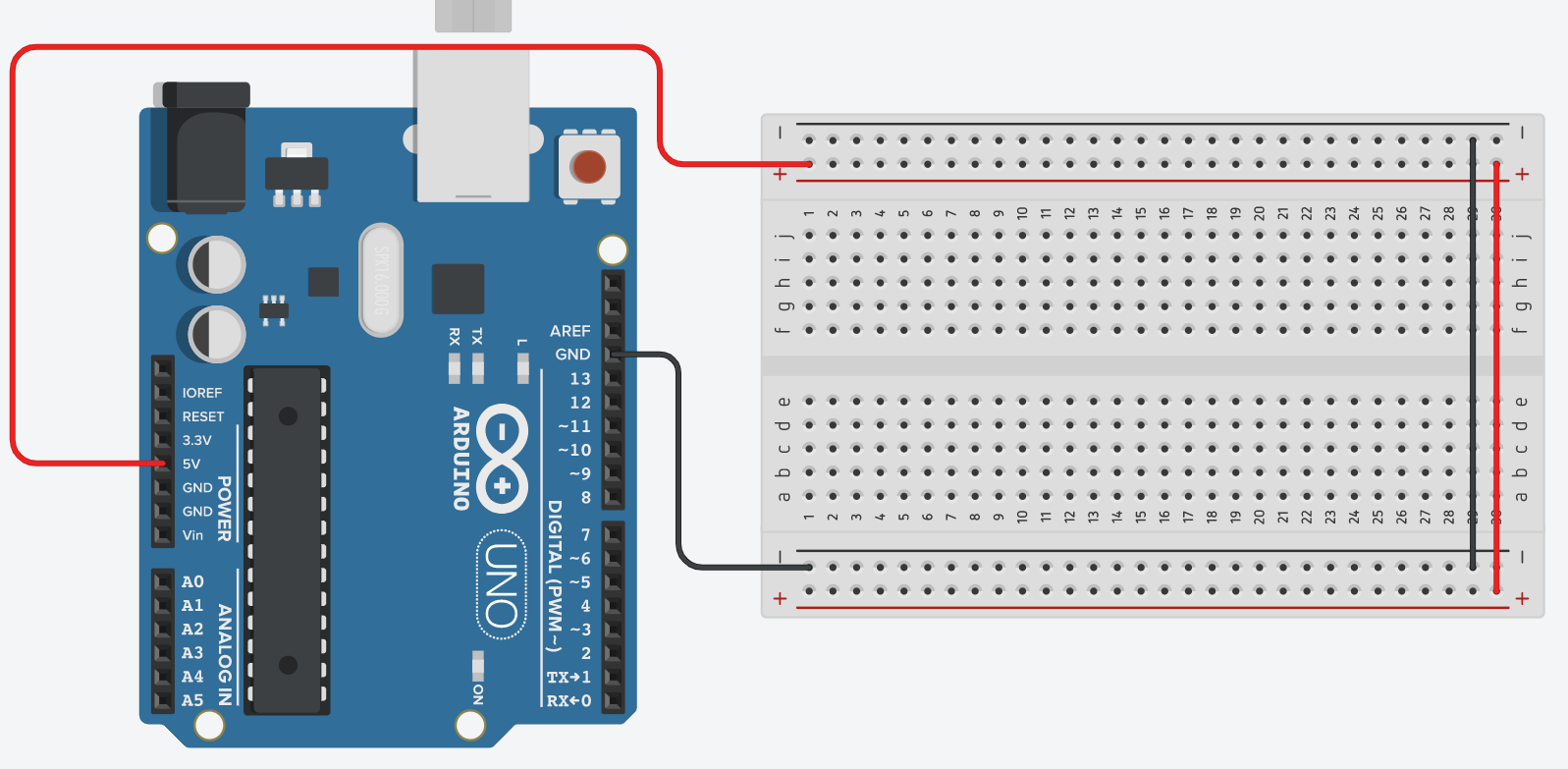
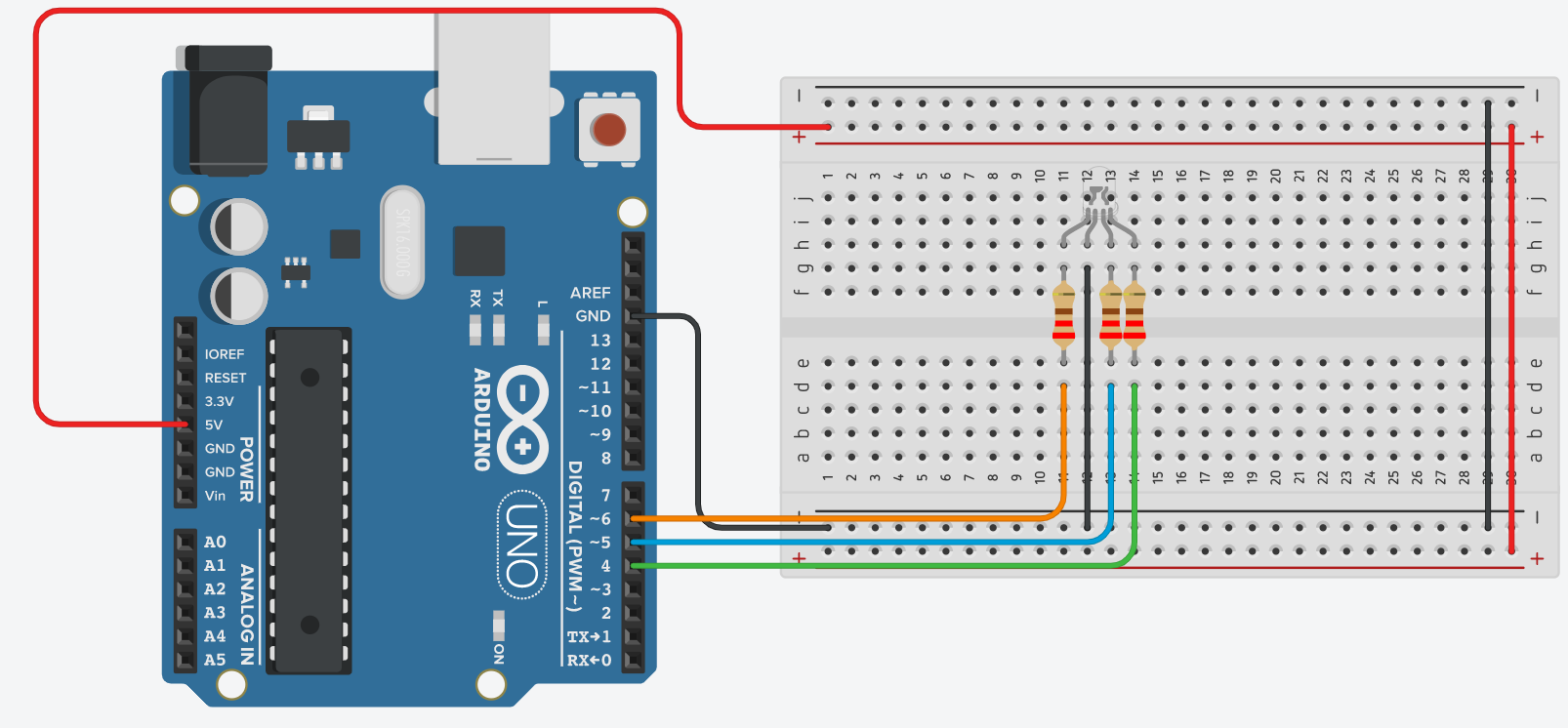
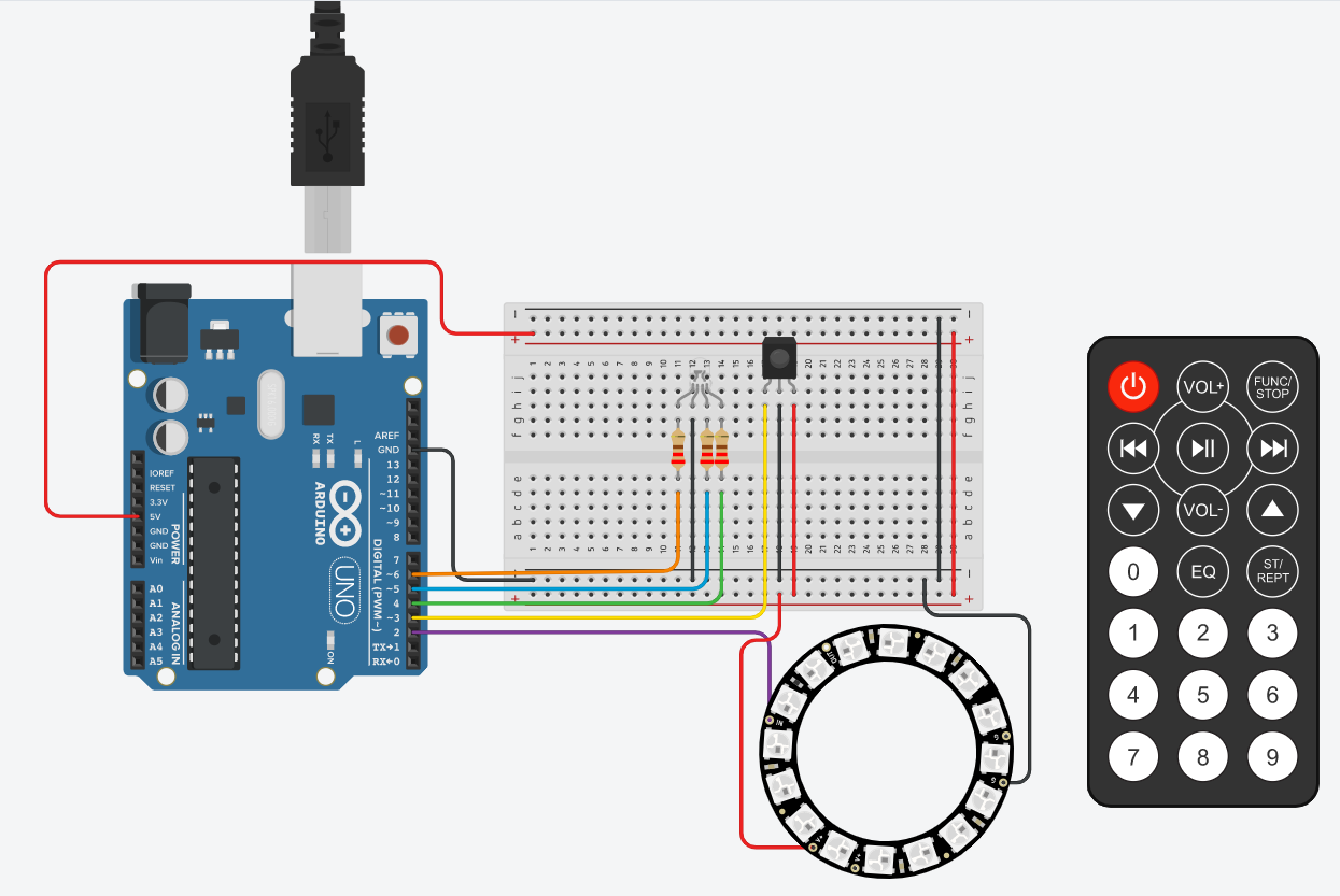
Take the Arduino and connect the 5v port to the positive side of the breadboard and the Ground from the Arduino to the negative side of the breadboard. Then at the end of the breadboard, connect the positive to the positive on the other side and the negative to the negative on the opposite sides, like shown above.
LED, Resistors & Cables
.png)
.png)
.png)
.png)
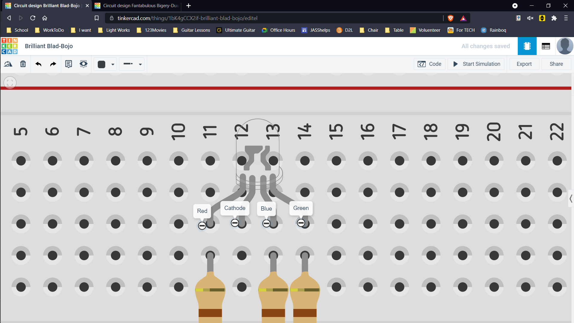
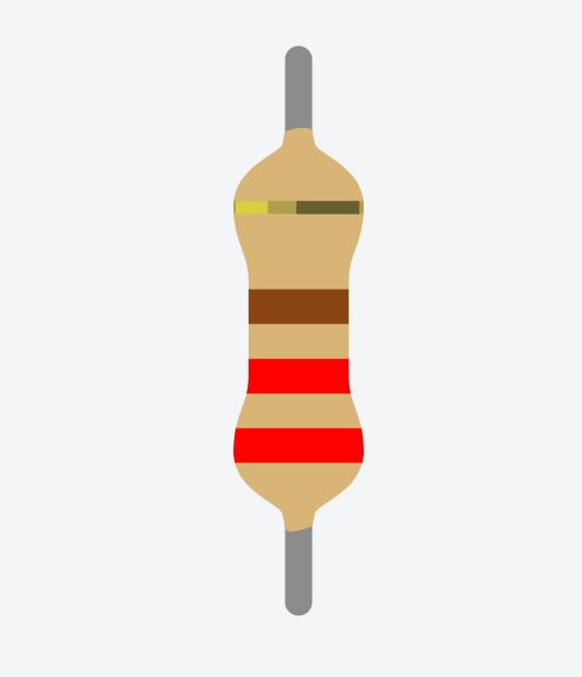
Next, connect the RGB led to the breadboard. Then take your 3 resistors (220 Ω) and connect them to the bottom of the breadboard. Beware of the Cathode. If you hover over the bottom pins of the LED, you will see Red, Cathode, Blue, Green. Connect the resistors from red, green and blue to the bottom half. Connect the cathode to the negative part at the negative side of the breadboard. Connect the Red cable to pin 6 Blue to pin 5 and Green to pin 4.
IR Sensor, Remote and Cables
.png)
.png)
.png)
.png)
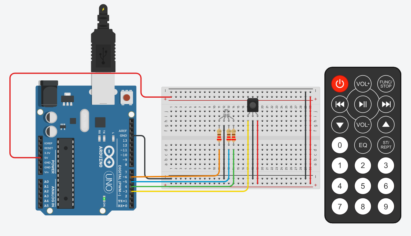
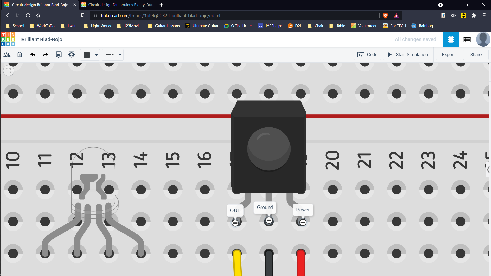
Take the IR Sensor and place it on the breadboard. Connect the pin to the right, to the Power line on the bottom of the breadboard. Connect the pin in the middle to the Ground line on the bottom of the breadboard. Finally, the pin to the left, to pin 3 on the Arduino. Then your circuit should look like the one on top. Bring the IR remote into the workstation.
Neo Pixel Setup
.png)
.png)
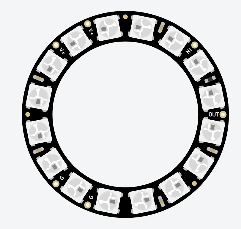
If you look closely in the Neo pixel, towards the outer parts you will see letters. This would depend on the number of pixels in your Neo Pixel. I am using a 16 LED Neo Pixel. So I have 2 G, 2 V+, IN and OUT. Connect one of the V to the power on the breadboard, Connect one of the G to the breadboard and Connect the In to Pin 2.
Arduino Code
Go to the code section in TinkerCad. It will be in the top right next to Start Simulation. then click the box right under it which says blocks and select the option of text. A pop-up will appear. Click continue. Select the text already there and erase it. Copy the code at the bottom and paste it there. If you copied what I did exactly, the code will work perfectly but if you changed it, depending on where you placed the pins the int will change and depending on your Neo Pixel, the number of pixels will change as well. all in the top and your IR receiver would change depending on where you connected the IR Sensor.
This is the link to my TinkerCad Lab