Light the Lamp - Electronics
by John Helfen in Circuits > Electronics
946 Views, 2 Favorites, 0 Comments
Light the Lamp - Electronics

Return to Previous Lesson: Popsicle Hockey Sticks - Craft
Lesson Overview:
In this lesson you will learn how to create the circuit that will light the lamp when the trophy is placed in the trophy stand.
Check out the entire "Anaheim Ducks: Light the Lamp Challenge" project on Tinkercad
What Is a Circuit?
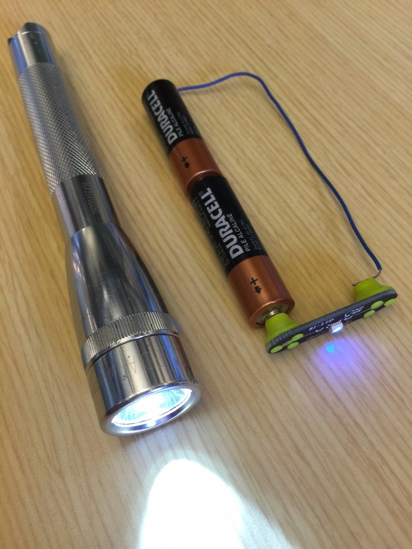
In this lesson you will learn how to add light and sound to the hockey rink you designed! What's a circuit? It’s a closed path or loop around which electric current flows. Different electrical parts are connected using wire to control the flow of current. Ever wonder how a flashlight worked? In a flashlight, wires connect batteries to an LED, allowing it to light up. Check out the how wire connects the batteries to a light in a flashlight! We will teach you how to design a circuit that will Light the Lamp when the someone scores a goal! Let's get started!
Instructions
Continue to the next step.
Lets Start to Build!

We can't see electricity but it is a type of energy, just like movement from a flowing river, heat from a fire, or light from the sun. An LED is a Light Emitting Diode and allows us to convert electrical energy into light. Since we can see light, it's a great way to look for electricity. Now you will make a circuit to light up your LED. You will need a battery source, a resistor and an LED.

Instructions
Click the +Components button, notice new parts appeared at the bottom.
Search for the "AA Battery" and click it once to add it to your circuit. Place the battery in the middle of your screen.
Add three more AA Batteries and Press the "R" key or the Rotate button so that it looks like the image above.
If you click the +Components button again the components menu will hide. Or click any clear area in the workspace to hide the components menu.
Click again on the +Components button, and add an LED, Resistor and a Slideswitch.
Continue to the next step.
Add Wires to Your Circuit
Electricity can be thought of like water that flows through pipes. It's time to add wires between the battery and components so that electricity can flow between them and connect the circuit.
This flow is called 'current'.
To connect the batteries together, follow the steps.
In 123D Circuits every component has "terminals". These are spots where you can click and connect one terminal to another terminal, joining parts together for electricity to flow.

Instructions
-
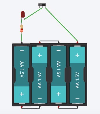
We want to connect the batteries together as in the image above. This is like the 4 AA Battery Holder that is supplied by the Anaheim Ducks kit for Light the Lamp.
-
The battery terminals are the small metal pins on the battery. The battery has a (+) for positive terminal in red, and (-) negative terminal in black. Hover over the terminal and a red box will appear on top of that point. This indicates where you can start a wire.
-
Click on the positive and negative terminals to connect them as above. You can change the color of the wire by selecting the wire and using the Breadboardwire box to select the colors of your choice.
-
Why are we connecting these batteries together?
Hint: Each AA battery is 1.5 Volts. We want a 6V battery, so we are connecting 4 of these 1.5V batteries together. 1.5V+1.5V+1.5V+1.5V = 6V. They are connected this way, in series, by connecting the (+) Positive to (-) Negative terminals of each battery so that in the end we have one big 6V battery with a (+) Positive terminal, and a (-) Negative terminal.
-
Continue to the next step.
Finish Up Wiring!

Your circuit should now have the battery connected, and you are ready to wire the resistor, LED and light switch.
If you look carefully, the LED has two leads. One is bent, and this is the 'Anode' or (+) Positive side of the LED. If you were looking at the actual part in your hand, the Anode would be slightly longer than the other lead.
The Ducks workbook has a helpful suggestion to drawing a stripe on this lead with a marker to keep track if you start bending it or connect it to another component.
The other LED lead is the 'Cathode' or (-) Negative side. If you hover your mouse over the leads, it will display which one you have selected.
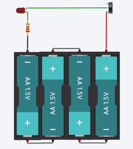
Connect the Circuit as below. You may need to Rotate parts to have them look like this in your circuit.

Instructions
Resistors help slow the current or flow of electricity in the circuit. This is just like how defense in hockey tries to slow the opponent from scoring. There are bigger Resistors and smaller ones. If you use too small of a Resistor, there is less 'defense' and too much current flows and the LED gets really bright and may burn out! Selecting the right size Resistor allows the LED to light up without getting damaged.
Click on the resistor. Change the values to be 220Ω by typing in 220 and selecting Ω in the dropdown. The symbol Ω, pronounced 'Ohm' is the unit of measurement for resistance.

Continue to the next step.
Light the Lamp!!

Now that everything is wired up, we will Light the Lamp!

Instructions
-
egin by clicking "Start Simulation". Next click the switch to turn ON the circuit. How does this switch work? If the switch is 'ON', everything is connected in a closed circuit and the LED lights up. When the switch is 'OFF', the connection inside the switch does not connect together, and the current does not flow to the LED and resistor, so it doesn't light up.
Hint: The Switch closes the circuit, and controls if the flow of current is ON or OFF. The current flows from the Positive (+) terminal of the battery through the switch to the LED and resistor, connecting back to the other end of the battery. This is called a circuit loop, and everything has to be connected with a conductive material- like metal wire.
-
Did you light the lamp? If the puck crosses the goal line and goes completely into the goal, the light is turned on by a goal judge. You are just like the goal judge! The light lets everyone in the arena know that a goal has just been scored!
-
Click on "Stop Simulation" button to stop the circuit from running in the workspace.

-
See how the switch, resistor and the LED are connected one after the other? They are all connected in Series as one part is connected right after each other. Electrical Engineers draw circuits in a diagram called a schematic. Look at this one that shows the circuit with the components in series.

-
Try changing the value of the resistor. Remember its like a big hockey defender. What happens when you increase it to 500Ω? Can you see the light turn when you Start Simulation? What happens if you decrease the resistance and run the risk of burning out the LED?

Hint: If the resistance is too low, lots of current runs through the LED which it can't handle so it burns out. Use your mouse to see what the message is over the LED with the big explosion on it! Current is given in units of Amperes or (A).
-
Continue to the next step to make it even better!
Making It Even Better!

So now you know how to light the lamp. What if you want to make it better and add some sound with a buzzer? We can convert electrical energy to sound energy by using a buzzer and electricity!

Instructions
Add the buzzer by clicking on +Components and searching for the "Buzzer". You will see this as a small round device. This is known as an active buzzer that makes a noise when you connect the battery terminals to it. Note it is labelled as (+) Positive terminal and (-) Negative terminals, and can be seen when hovering over it with your mouse. In the actual Buzzer part from the kit, the (+) Positive terminal usually has red wire and the (-) Negative terminal has a black wire. When connected to a battery terminals of the same charge or polarity, the buzzer will sound as the circuit is completed.
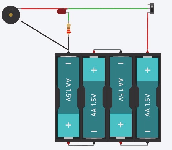
Add the buzzer across the LED and Resistor. The Buzzer is now in a parallel circuit to the LED and Resistor. The Buzzer is connected to the Anode or (+) of the LED and the other end is connected to the (-) Negative terminal of the battery pack. Earlier we showed a series schematic. This diagram now shows the Buzzer is Parallel to the LED and Resistor. Can you see the Parallel lines in the diagram?

Click on the Start Simulation button and try it out! Remember to turn on the switch in the circuit.
Now you are a pro! You can Light the Lamp with both an LED light and a buzzer. This is converting electrical energy into light and sound!
Continue to the Next Lesson
In the next lesson you will learn how to create a 3D printable Stanley Cup trophy using Tinkercad.
Next Lesson: Raise the Cup - 3D Print
