Light Up Skull- Arduino Circuit Tutorial
by qsrxth6nnd in Circuits > Arduino
245 Views, 0 Favorites, 0 Comments
Light Up Skull- Arduino Circuit Tutorial

Today, we will be making a circuit to place in a empty fake skull based on my Virtual Escape Room. The Escape Room was to find an ancient crystal skulls hidden acoss the globe. These skulls that we find, That being said, we will be creating a circuit to replicate a light up skull that will light up at night when the sun goes down. We will be using tinkercad in order to accomplish this, we wil be using an arduino uno to simulate the lights. We will use an input of a light sensor, and a UV output.
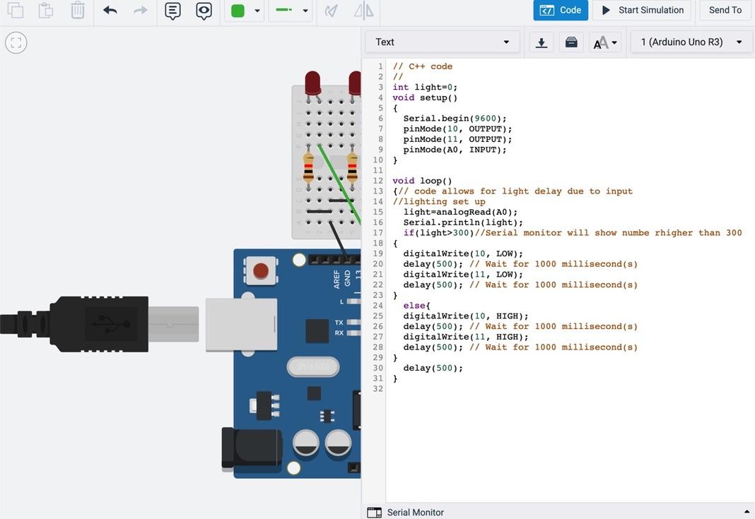
Set Up Code Through the Code Box in Tinkercad.

// C++ code // int light=0; void setup() { Serial.begin(9600); pinMode(10, OUTPUT); pinMode(11, OUTPUT); pinMode(A0, INPUT); } void loop() {// code allows for light delay due to input //lighting set up light=analogRead(A0); Serial.println(light); if(light>300)//Serial monitor will show numbe rhigher than 300 { digitalWrite(10, LOW); delay(500); // Wait for 1000 millisecond(s) digitalWrite(11, LOW); delay(500); // Wait for 1000 millisecond(s) } else{ digitalWrite(10, HIGH); delay(500); // Wait for 1000 millisecond(s) digitalWrite(11, HIGH); delay(500); // Wait for 1000 millisecond(s) } delay(500); }
Downloads
Setting Up Hardware

Step 1: Add an arduino uno from the components bar.
Step 2: You will then add a breadboard mini and place it above the arduino.
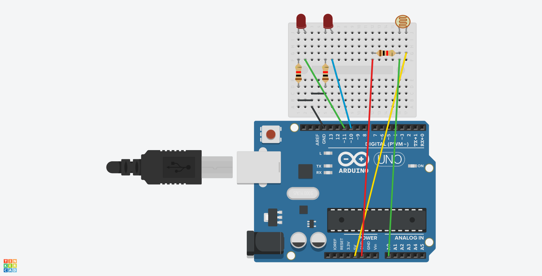
Step 3: You will then add two LEDs and place one at J1 and 2, and the second on J 5 and 6 as seen in the picture.
Step 4: You will then add a photo resistor and place it in the top right in the spot J 16 and 17 as seen in the picture.
Step 5: You will then add 3 resistors, one placed with each end in F1 and D1. The seconf one will have to first half placed in F5 and D5, and the last one will have one half placed in G12 and G16.
Step 6: You will now add two black wires, one in B1 and 3, and the second in C3 and 5.
Step 7: You will add another wire, color black in A3, then add the other end into the arduino in the GND.
Step 8: You will now add 2 green wires. For the first one, place on end in F2, and the other end in 11 of the Arduino. For the second one, you will place one end in F16 and the other end in A0.
Step 9: You will add a yellow wire, one end in G17, and the other end in 5V
Step 10: You will lastly add a Red wire, one end in F12, and the other end in the arduono in the GND of the power side.
Last Step: You should have copy and pasted the code into the code box, if you did that, then you are set to try it out.
Playing Puzzle
To make this puzzle function, you will press start simulation which the LEDs will light up. , Then click on the photoresistor to which it will show a little bar, when you slide it to the sun, the lights will turn off, showing how at night, the lights for a crystal skull will light up.