Light-Up PCB Pins
Hello! Welcome to another Othermill project tutorial! I'm Sam DeRose, an intern here at Other Machine Co.
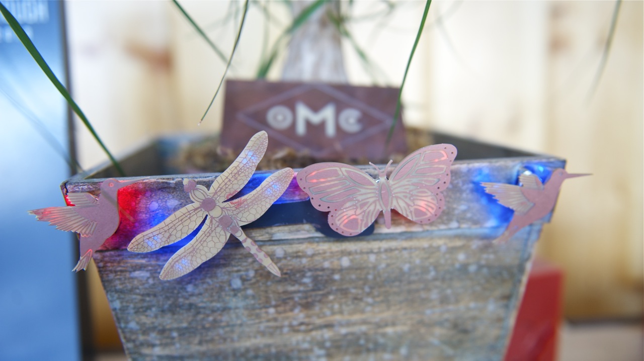
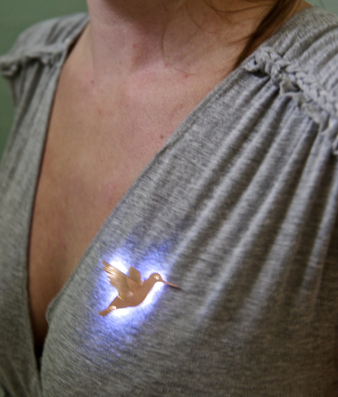
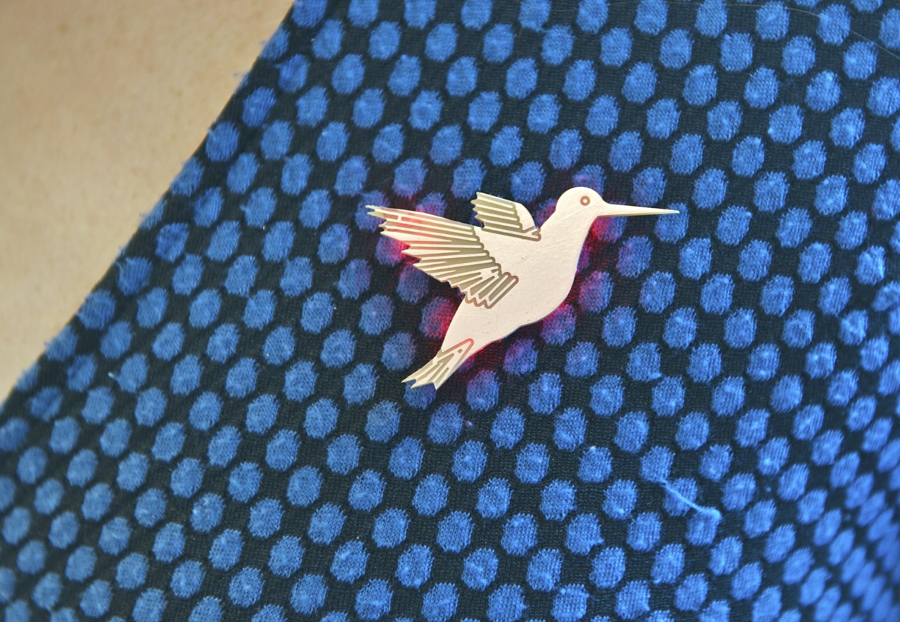
This project is a spin-off from my PCB Hummingbird Necklace. This time, I made it with the battery and switch built in so the necklace could be used as a pin. Now you can show off your glowing designs in many more places!
Tools, Materials, and Files


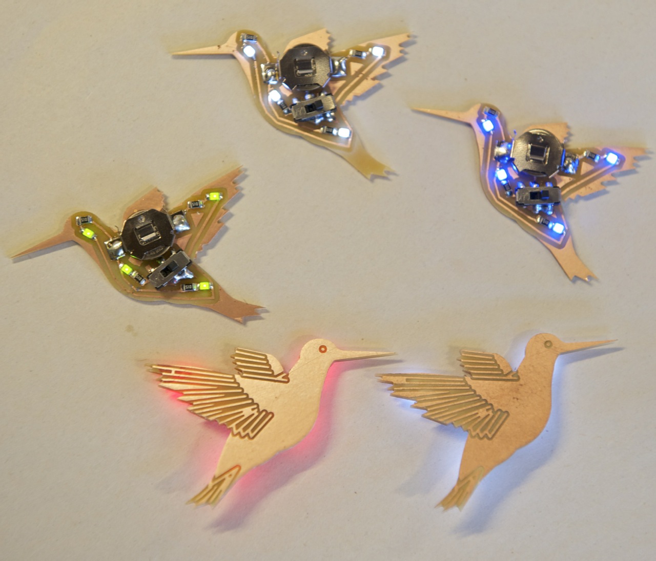
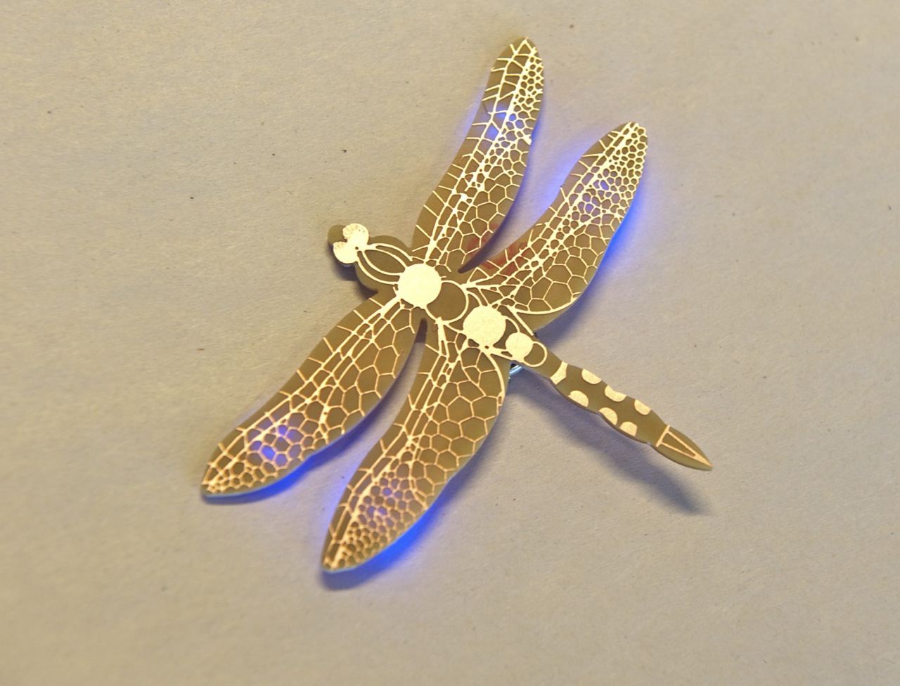
These pins are made from double-sided FR-1 circuit board blanks. The front is etched with the design and the back is etched with the traces for the electronics. All of the versions have a switch except the dragonfly—there was no room! To turn it on and off, you have to remove the battery.
This project assumes you have solid working knowledge of soldering and reading circuit board files to place components correctly.
TOOLS
- Othermill
- Computer with Otherplan installed
- Flat end mills: 1/32", 1/64", and 1/16"
- Soldering iron and solder
- Hotplate or toaster oven (optional) for reflow soldering
- Scotch-Brite pad
MATERIALS
- PCB blank, double-sided, FR-1
- Tape, double-sided
- Solder paste (optional) for reflow soldering
- Magnet, tiny but strong
ELECTRONIC COMPONENTS
- LEDs, surface-mount (4) your favorite color
- Resistors, surface-mount, 40–50 ohm (4)
- Battery holder, surface-mount, CR1025
- battery, 3-volt, coin cell, CR1025
- On/off switch, surface-mount, small
FILES
Choose at least one of the following, all of which are in the .zip file attached to this step.
- Hummingbird_Pin.brd
- Butterfly_Pin.brd
- Dragonfly_Pin.brd
Downloads
Set Up Otherplan


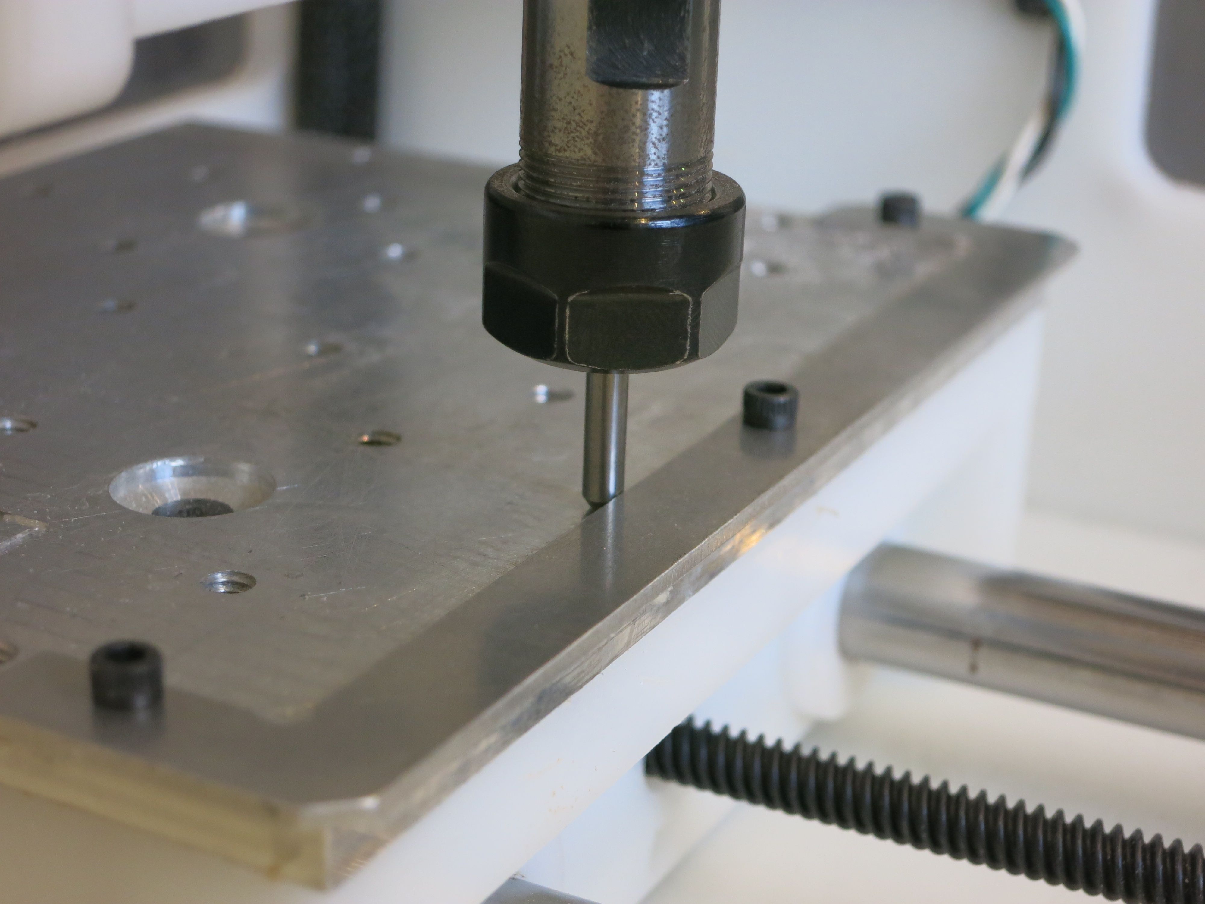
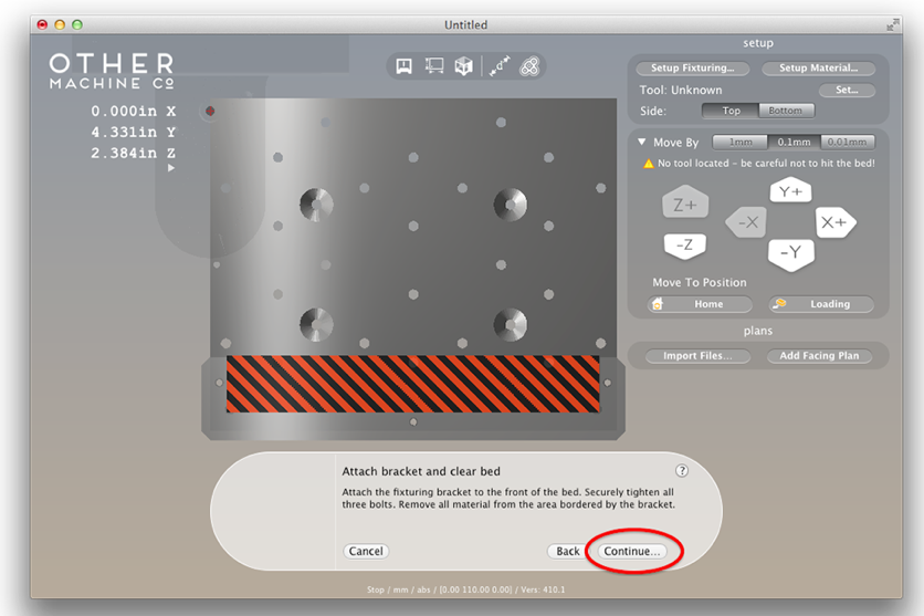
1. Power up the Othermill and home the machine by clicking the "Start Homing" button. Click on the "Loading" button to bring the bed forward.
2. Install the alignment bracket with the screws and the wrench in the accessory kit. The screws don't need to be too tight, just tight enough so the bracket is secure.
3. Align the files to the bracket by right-clicking on the file rendered on the bed in Otherplan. Select Align To > Bracket from the context menu. You can also do this through the Setup Material window.
Note: Aligning to the bracket is important, otherwise the top and bottom of your pin will not align properly.
4. Set up the material by choosing "Double-Sided FR1" in the Setup Materials menu, and enter the dimensions.
5. Download the attached .zip of .brd files, then extract and import them into Otherplan.
6. Select 1/32'' and 1/64'' flat end mills in the file windows that pop up in Otherplan.
If you need a refresher on how to use Otherplan with the Othermill, check out our Getting Started guide.
Cut the Circuit Side of Your Board
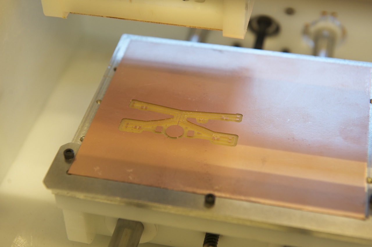
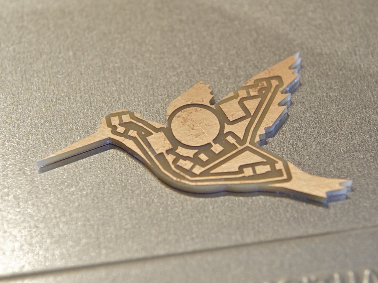
1. Put an even layer of double-sided sticky tape on one side of the the FR-1 board, measure its thickness, and stick it down to the machine bed, with the lower left-hand corner of the board flush with the left corner of the bracket, like so:
2. The Othermill decides which tool it need to use first. Once your material is set up and everything else is correct, click on "Cut," and the machine will let you know which tool you should use.
3. Once the tool has been set up, it will automatically go through the tool touch-off sequence and begin cutting.
The circuit side of the board will cut first. When that side is done, the machine will stop so you can flip the board over both in Otherplan and in the actual machine.
Cut the Decorative Side of Your Board
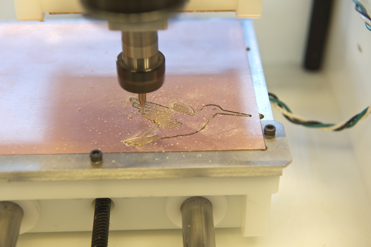
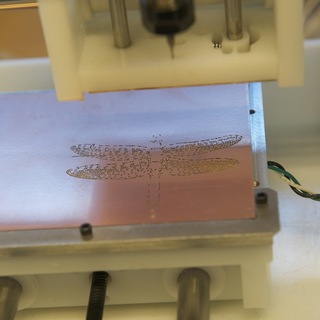
Now it's time to flip the board over!
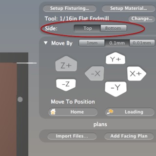
1. In Otherplan, locate the "Top/Bottom" toggle button in the upper-right hand of the window, under Tool. Toggle the button to "Bottom," and you'll see the rendered board flip over on the machining bed, revealing the pretty side of your pin.
2. Now do the same thing on the Othermill. Take the board off the bed and carefully peel off the tape. Flip the board over, dust it off, and place another layer of double-sided tape on the surface you just milled.
3. Hold the board, tape side up, so that the part you just milled is in the lower left-hand corner. Flip the board over so the milled part is on the bottom and press it down so it's flush with the right-hand corner of the bracket.
4. Make sure everything looks okay, and press "Cut." The machine will tell you what tool should be in the spindle and prompt you if you need to change it. The machine will then cut the design.
If there are burs left on the copper or plastic after milling, clean them up with a Scotch-Brite pad. Be sure not to use steel wool near the machine, as the fragments can damage motors and bearings.
Add Light
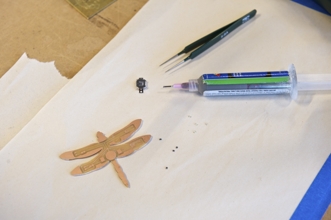
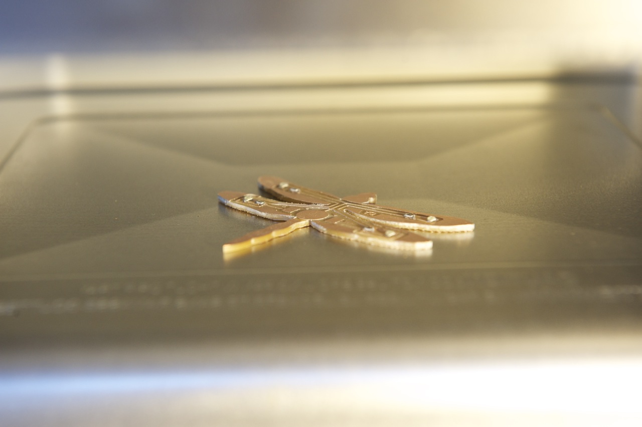
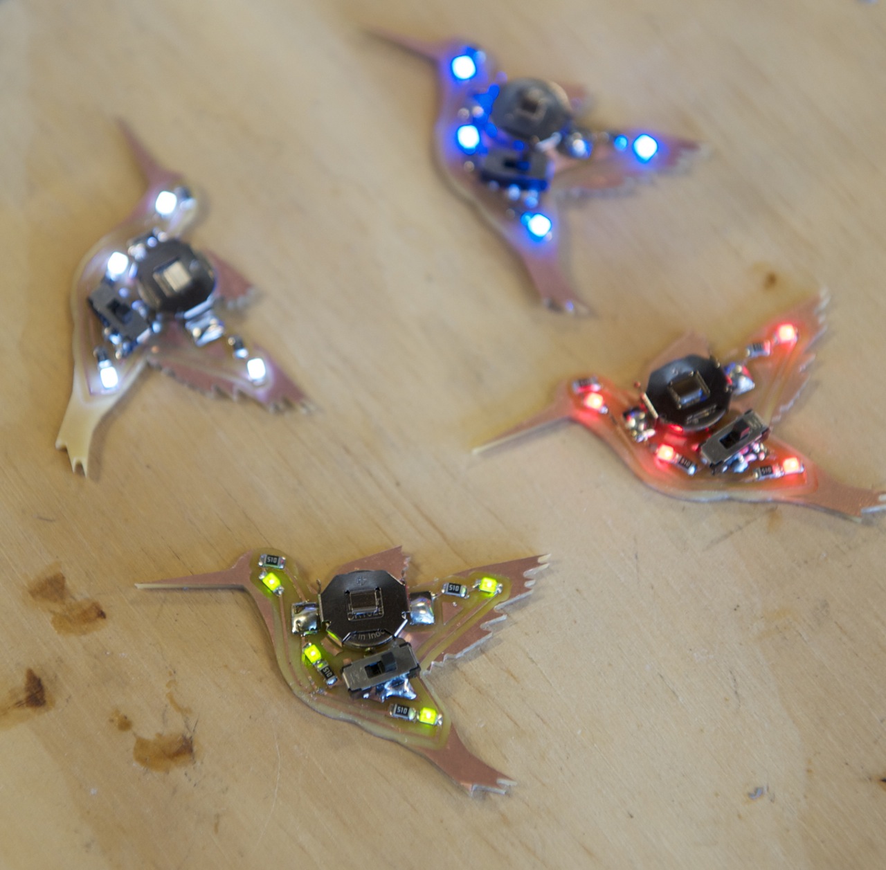
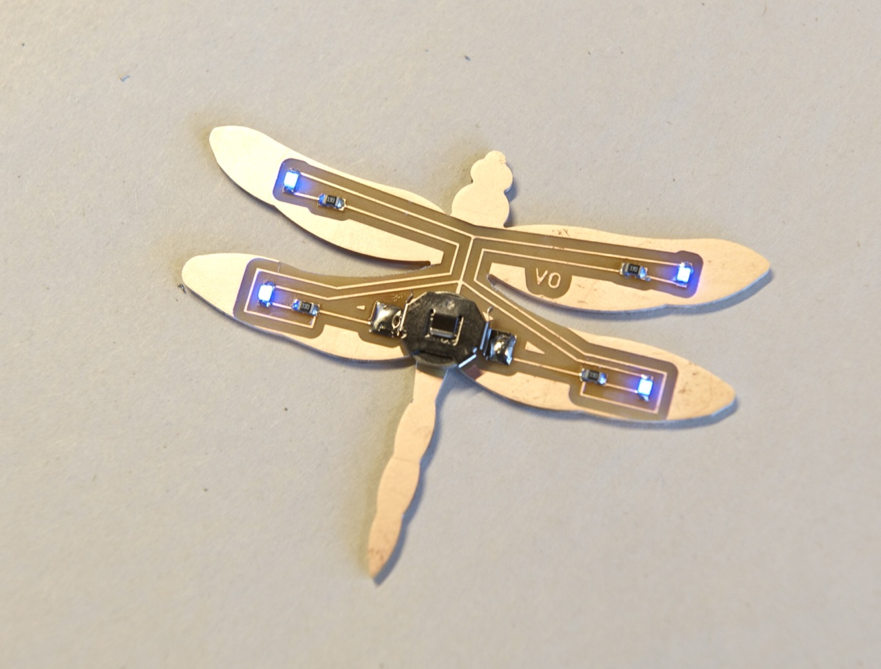
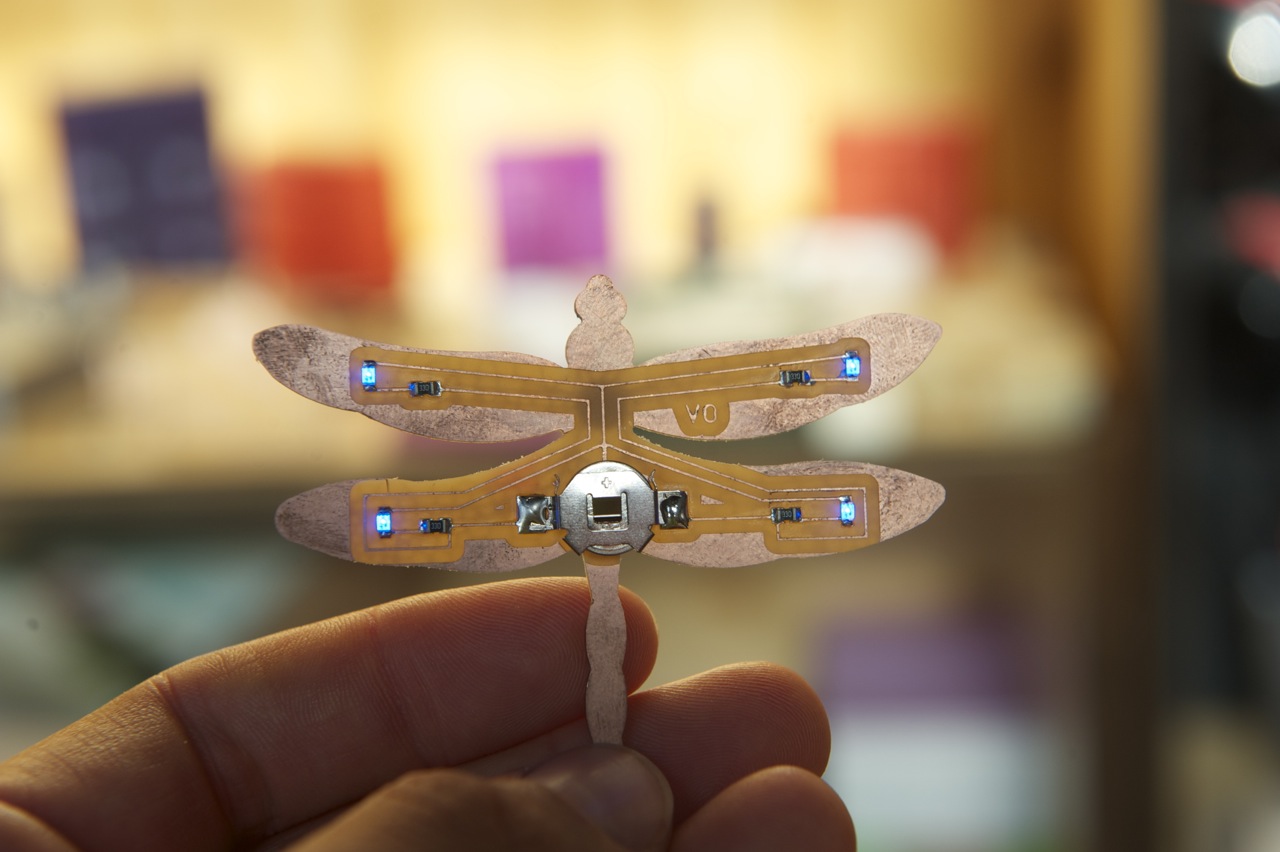
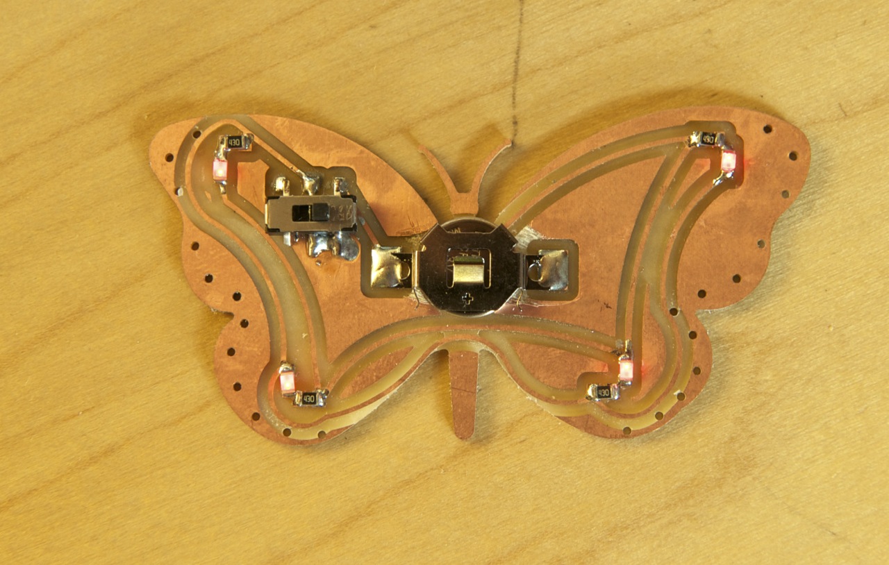
There are several ways to solder the electronic components on to your board. I attached the larger components, like the switch and battery holder, by hand using a soldering iron. I used reflow soldering to mount the smaller, surface-mount (SMD) components like the LEDs and resistors.
Reflow soldering requires solder paste and a hot plate or toaster oven. For boards like this, either heat source works fine, but I've found a toaster oven provides more even heat. For more information on reflow soldering, read Step 4 of the PCB Hummingbird Necklace tutorial.
When you've attached all the components, slip in the 3-volt coin-cell battery and flick on the switch! If the LEDs don't light up, then its time to debug your circuit. Once again, Step 4 of the PCB Hummingbird Necklace tutorial has some good debugging tips.
Wear It!
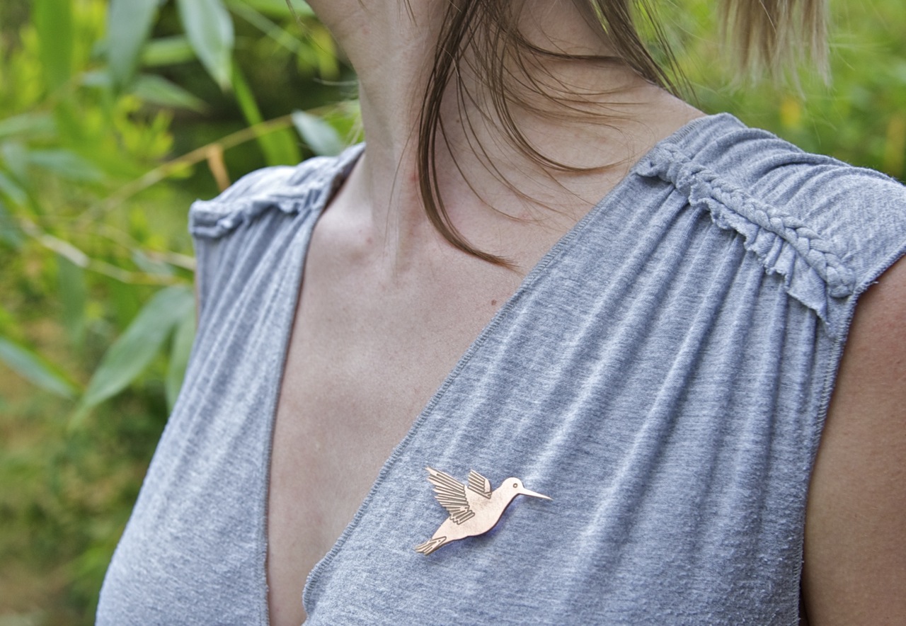
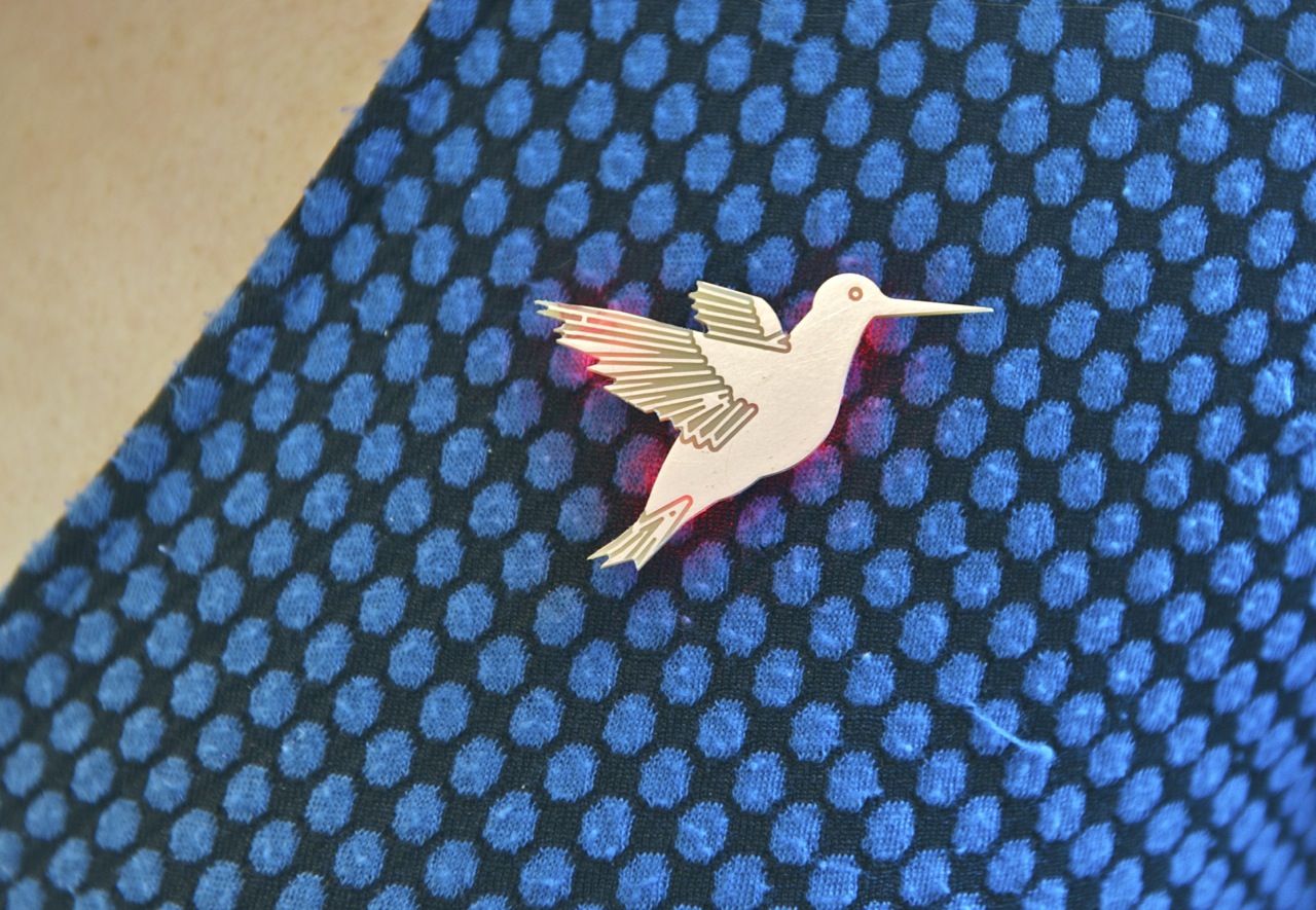
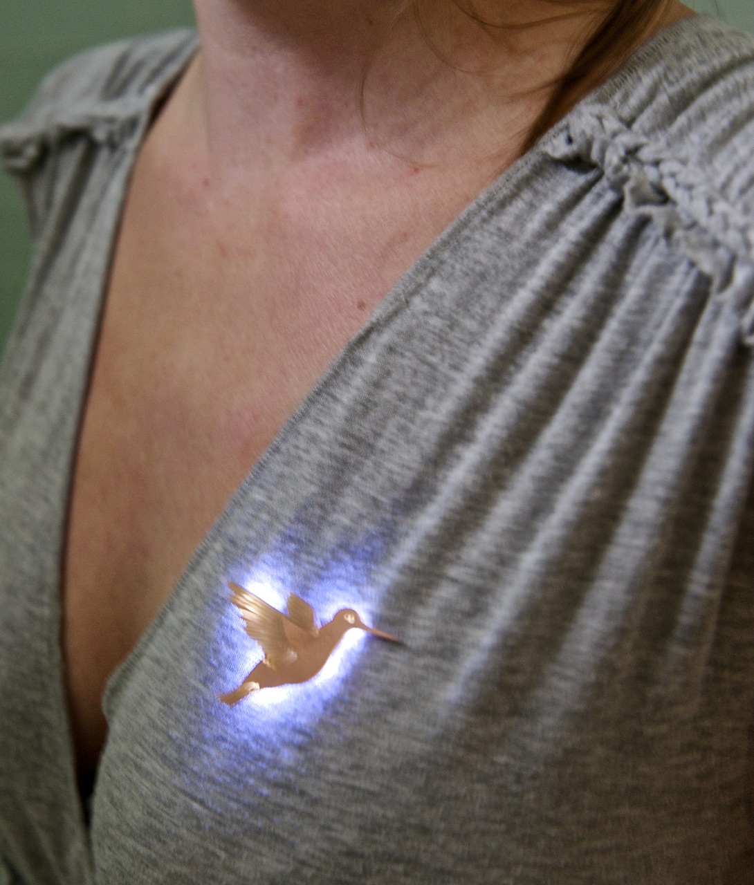
Use a magnet inside your clothing to hold the pin in place, magnetizing to the battery holder on the pin. The nice thing about these pins is that they still look great when the LEDs are off, so you can conserve battery power for just the right occasion.
Of course you should feel free to use this basic design to make your own custom pins. We'd love to see a picture if you make one of these pins, so please pics in the comments below!
Got a questions? Send us a note at support@othermachine.co. We're happy to help!