Light Sensor for Boat Navigation Light
by sloop sailboats in Circuits > Sensors
381 Views, 0 Favorites, 0 Comments
Light Sensor for Boat Navigation Light

About Navigation Lights in Boats:
It is necessary for boats to have navigation lights in order for them to be visible to other boats or people on land. These lights must be turned on at night when the level of light outside makes it difficult for boats to be seen. We will make a sensor that will automatically turn on navigation lights when the level of light gets to a certain “dark” level of light.
Photodiodes Crash Course:
Photodiodes are light sensitive diodes that generate a reverse bias current when exposed to light. They can be modeled as a current source for a given irradiance from the ambient light. The reverse light current generated by the photodiode can be manipulated to cause a signal to turn on or off. For example, a smoke detector could go off and in our case, a light will be turned on. For this tutorial we will be using the QSD2030 photodiode.
Downloads
Supplies
Block Diagram
Our design will be based on the following simple block diagram.

Light Sensor Circuit
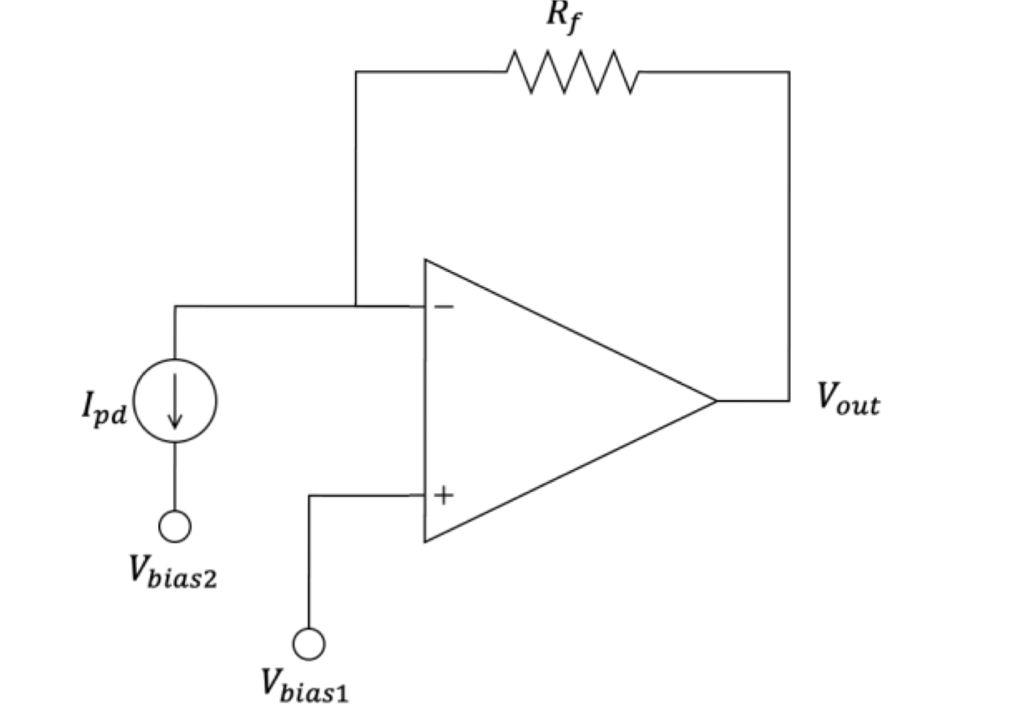
The light sensor circuit has the photodiode modeled as a constant current source, under the assumption that this is the circuit when the photodiode is being exposed to light. We want the reverse bias of the photodiode to be 5V (because we want to use Fig. 1 on the datasheet which is based on VR = 5V). So, by setting Vbias1 = 5V, thus imposing 5V at the node between the current source and Rf, we get Vbias2 = 0V.
We know that Ipd = (Vout-Vbias1)/Rf. Then, Vout = Ipd*Rf+5V. Thus, if we want to generate a 8V output at Ipd = 15A, Rf = 8V-5V15A =200K. The op-amp in this stage of the circuit is going to be a TL081. The TL081 works well in this situation because its output voltage reaches around 40V, as seen in the Figure 6-37 in the datasheet.
We are setting our “lots of light” condition to be the light level in a classroom/lab. It is recommended that a classroom have at least 300 lux of light, which converts to 300 lumens/m2. 300 lumens/m2 corresponds to 0.3 mW/cm2 for an efficient LED lightbulb.
Thus, based on the reverse light current vs emitter output power plot in the photodiode data sheet, our initial estimation of Ipd for the “lots of light” condition is around 15µA or greater.
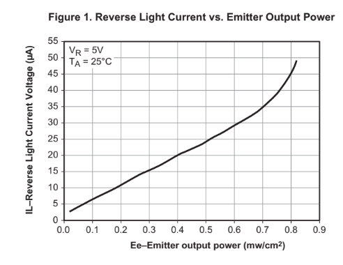
Figure 1. The reverse light current versus emitter output power for the QSD2030 photodiode.
We choose Rf to be 200 kΩ. So, our threshold Vref = 8V because when there is lots of light Ipd is at least 15µA and Vo = IpdRf + Vbias1 = (15µA)(200 kΩ) + 5V = 8V. We will thus define the “low light” condition as Vo < 8V.
Note that we did not end up using this Vref = 8V value. We ended up changing our threshold to Vo ~3V later to effectively distinguish between “no light” (Ipd ~ 0A) and “light” (Ipd > 0A) for the hardware.
Comparator Circuit and Inverting Amplifier Circuit:
In order to impose a threshold into our system, we need to use a comparator in combination with an inverting amplifier. Since the voltage coming out of the photodiode stage will be larger if there is a lot of light in the environment and smaller if there is not a lot of light, we can impose a threshold to make the voltage corresponding to high light environments go to a low voltage (-15V) and the voltage corresponding to low light environments go to a high voltage (15V). The navigation running lights require a 12V input voltage to turn on.
Since a comparator follows the rules of if Vo < Vref → Vout = +Vcc and Vo > Vref → Vout = -Vcc, we will first need to assign a high voltage to high light environments and a low voltage to low light environments using the comparator. We will use Vref = ~3V, +Vcc = 15V and -Vcc = -15V. Then we will use an inverting op amp to output a voltage of Vout = 0V for an input voltage of 15V (light conditions) and Vout = 15V for an input voltage of -15V (no light conditions). Note that the voltage of 15V was chosen because the OPA551 which is to be used for the inverting amplifier op amp has a wide voltage swing of 2V and we wanted to ensure that the light would receive at minimum 12V when we want the light to turn on.
The full circuit diagram is shown below:
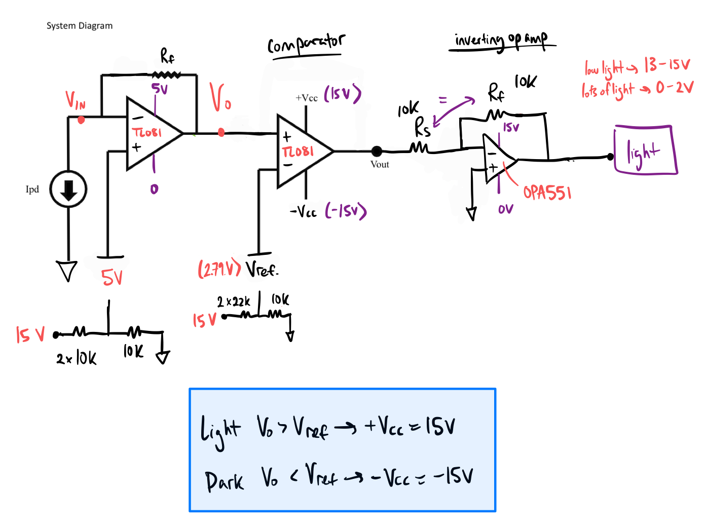
Note that we will use the TL081 for the first two op amps and the OPA551 for the last op amp before the navigation light. We will use the QSD2030 for the photodiode. We will use two power supplies to get 15V and -15V and then use voltage dividers to get the 5V and ~3V that are also needed in the circuit.
Other Considerations:
Noise considerations:
The flickering of LEDs due to having an AC power supply could cause noise in the system. However, note that the sun does not flicker and the intended light source is the sun so we will go use an adjustable phone flashlight in order to test our sensor in a more realistic setting that has minimal noise. Note that while testing the circuit, flickering did not seem to impact the circuit’s functionality.
Bandwidth/Power considerations:
We chose to use the OPA551 as the final inverting op amp before the light because the power of the light is 2W and it requires a supply voltage of 12V, so this means that the light needs an input current of 1/6A or ~167 mA. The OPA551 has a high output current of 200 mA continuous which satisfies the input current requirement for the light.
One thing to note for the OPA551 is that it has a wide output swing of 2V from the rail. In order to ensure that the light receives sufficient voltage, we want to supply the OPA551 with -15V (when it is dark) so that the output of the OPA551 (input to the light) will fall within the range of 13-15V when we want the light to be on. Note that the supply voltage range for the OPA551 is +/- 4V to +/- 30V and 0-15V falls within this range.
We chose the TL081 as the light sensor circuit op amp and the comparator op amp. This is because the TL081 has a supply voltage of ±2.25 V to ±20 V, 4.5 V to 40 V, so the desired supply voltages of +/- 15V, 5V, and ~3V all fall within this range.
Frequency Response/gain considerations:
We need to consider that the gain is within the bandwidth when the input is maximum and that the light will still turn on when the input is minimum. We ensured this through simulations below by adjusting Rf and Vref .
Initial Testing of Input Stage:
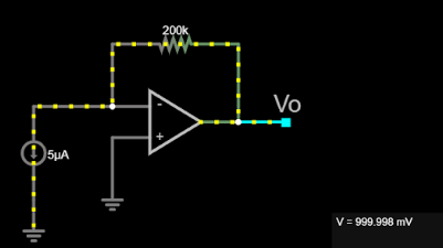
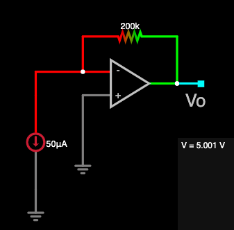
We tested our sensor using Falstad. We did not set the Vbias1 to 5V because we modeled the photodiode as a current source. When Ipd was set to 50µA (maximum lots of light), Vo was 5V as expected. Note that the op amp railing out at 5V. When Ipd was set to 15µA (lots of light), Vo = 3V as expected. When Ipd was set to 5µA (low light), Vo ~ 1V as expected. See figures below. Note that 0V < Vo < 5V is within spec for the TL081 which has a maximum output voltage of 40V.
When Ipd = 15µA (classroom “lots of light” condition):→ Vo = 3V

When Ipd = 5µA (around minimum current):→ Vo = 1V
When Ipd = 50µA(maximum current): → Vo = 5V
Note that the op amp is railing out, but this is okay.
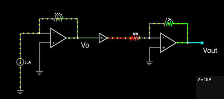
System Simulation:
We tested our entire system using Falstad. There was no comparator with rails so we used a Schmitt trigger with the lower and upper thresholds equal to ~3V and the slew rate set to 20mV/ns (based on TL081 slew rate of 20 V/µs). We set the high logic voltage to 15V and the low voltage to -15V corresponding to +Vcc and -Vcc respectively.
When Ipd was 5µA (low light), Vout = 15V as expected. In testing Ipd = 15µA, we realized that the output voltage was still 15V, so we adjusted our original reference voltage to be <3V to ensure that Vout ~0V (the light will be off) when Ipd is 15µA. When Ipd was 50µA (maximum lots of light), Vout ~ 0V as expected.
Ipd = 5µA: (Vout is expected to be 15V)
Note that we can see the negative voltage generated at the output of the comparator in red.
Ipd = 15µA: (Vout is expected to be ~0V)

Ipd = 50µA: (Vout is expected to be ~0V)
Note that the op amp is railing out, but this is okay.

Final Result
The circuit on the breadboard is shown below:
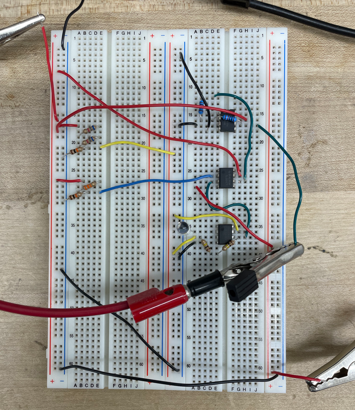
The operation is shown below. When the lights were on, the circuit was in the “lots of light” condition and thus did not turn on the navigation lights. When the photodiode was covered or the lights were turned off the circuit was in the “low light/no light” condition and thus turned on the navigation lights. The conditions are shown below:

Figure. The navigation light turns on in “no light” conditions.

Figure. The navigation light turns on in “low light” conditions.

Figure. The navigation light does not turn on in “lots of light” conditions.