Light Sensor
We will be making a light sensor. This inscrutable will teach you how to turn on and off a LED with the amount of ambient light in the room. This project will open up the world of microcontrollers. Microcontrollers are used in every integrated circuit that does not have a CPU. In order to complete this project, you will need some coding experience and be able to operate a breadboard. We will be using the PIC16f690 microcontroller to control our circuit. You will learn how to download all the operating software, and setup and execute your circuit with the PIC. If you are using a different microcontroller some of the steps will be different.
Time to completion: 1h
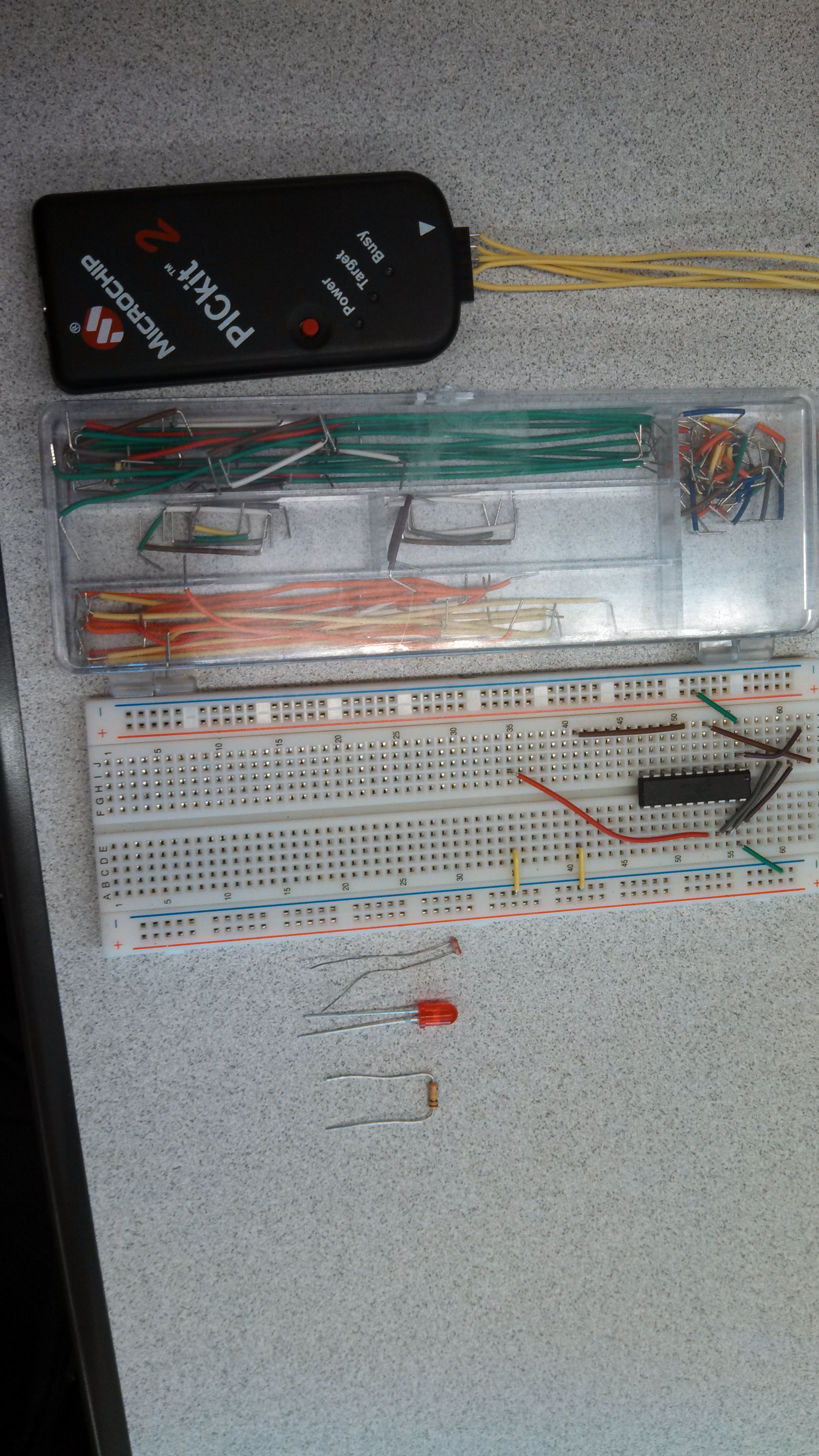
Materials:
- 100k ohm resistor
- PIC16F690 microcontroller & data sheet
- PICkit3
- Breadboard & breadboard wires
- LED
- Photo resistor
- Multimeter
- Two banana to pin connectors
Software:
- MPLAB® X IDE v2.05: This is your programming environment
- MPLAB® XC8 Compiler: Compiler for the PIC16F690
- PICkit3 operating software
Downloads
Downlading the Coding Enviromet
In order for us to put code on the PIC we first need a coding environment where we can make our projects. This is also where we will be writing and possibly debugging our C code.
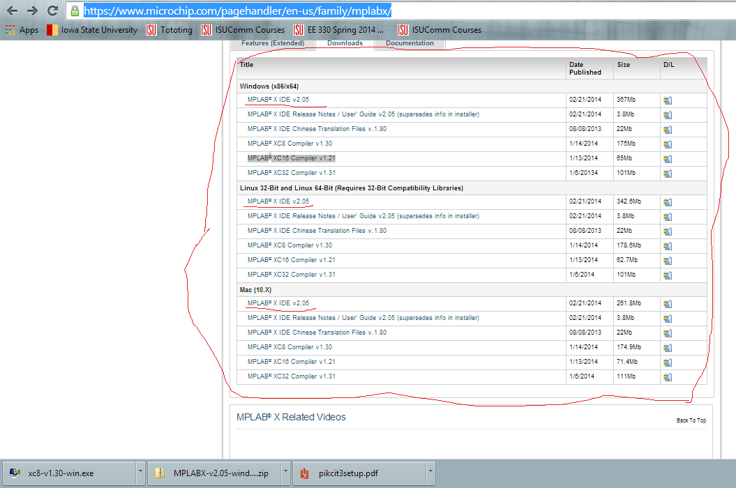
- Downloading the environment
- Please go to https://www.microchip.com/pagehandler/en-us/family/mplabx/
- Download the most up-to-date environment on the machine EX: MPLAB XIDE 2.05
- If you are using a PICkit2 download MPLAB XIDE 2.00
- Follow the installment instructions
Downloading Compilers and PICkit Operationg System

Once we have our coding environment we need something to check our code and download it onto our PIC; in order to do this we need to have a compiler. It is important that you have a compiler with the same number of bits as your PIC. If you do not know how many bits your PIC is, look at your data sheet. We will also need operating system for the PICkit3.
- Downloading the compiler
- Go to http://www.microchip.com/pagehandler/en_us/devtoo...
- Download the XC8 compiler.
- If you are using a different PIC, download the one with the correct bits 8,16, 32.
- Follow the installment instructions.
- Download the PICkit
- http://ww1.microchip.com/downloads/en/DeviceDoc/PI...
- Follow the installment directions
Configuring the Sensor
In this step we will be finding out what voltage will be inputted to the ADC of our PIC microcontroller, and what that ADC value will be.
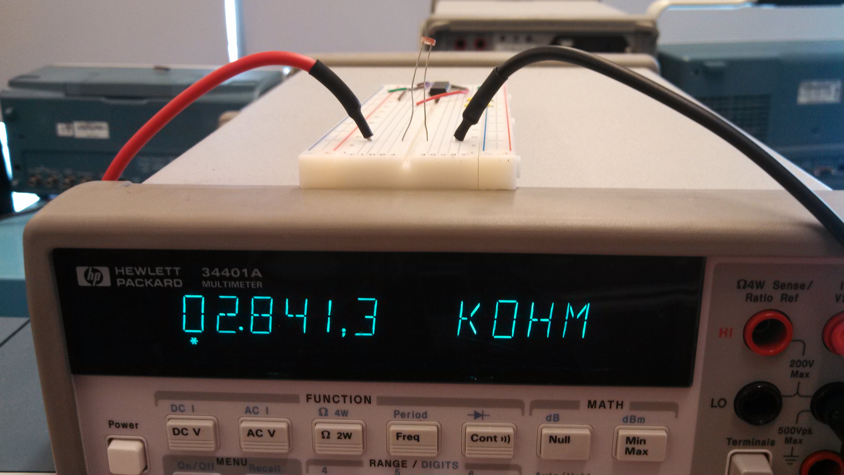
- Finding the resistance of the photo resistor
- Set up the mulitimeter to read resistance
- Put the resistor in the breadboard and read the resistance.
- It is important that in this step you have the same amount of light when you want to turn on the LED.
- Read the resistance off the multi mentor. EX: 51k ohms
- Clear the bread board
Calculations

In this step we are going to figure out the voltage that the PIC is going to read, and calculate the correct ADC value for our code.
- Calculate the voltage at the ADC
- Using a voltage divider method we can solve for the voltage across the photo resistor
- Look at picture above for calculation
- Calculate the ADC value
- We are using a 10 bit ADC, so n=10
- Vreff=5V can be changed in the registry for the ADC conversions
- Look at picture above for calculation
Connecting the PICkit
In this step we will start the connection to the PICkit. It is important to get the pins correct in this step or you might break the PIC. Pleas double check your work with the attached PDF and the datasheet.
- Put the PIC in the center of the breadboard
- The notch is at the top of the PIC indicating that pin 1 is the first on to the left.
- Connect all the pins on the PICkit to the respected pins on the PIC.
- If you have the PIC16f690
- MCLR pin 4
- VDD pin 1
- VSS pin 20
- ICSPDAT pin 19
- ICSPCLK pin 18
- The connection is the same order on the PICkit
- Pin 1 has the arrow pointing to it.
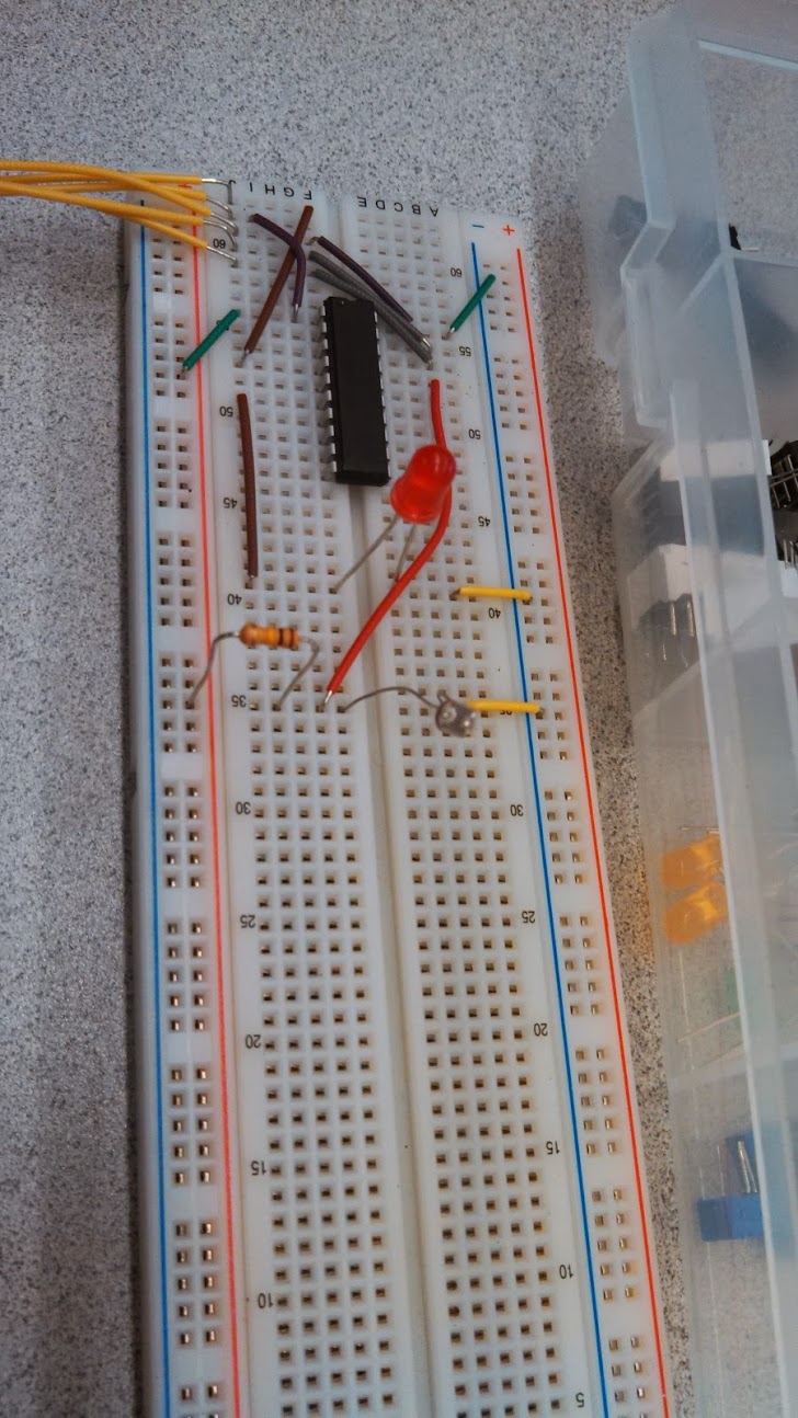
Seting Up the Circut
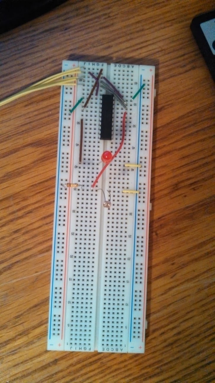
In this step we will be setting up the PIC for programming. Please look at the data sheet and picture if you are stuck. In the picture, the yellow wires are going to the PICkit.
- Make a voltage divider on the bread with the photo resister connected to ground.
- Connect a ADC pin to read the voltage across the photo resistor. EX: pin 17
- Connect a LED from a pin on the PIC to ground. EX: pin 6
- Make sure LED is forward biased.
- Do not worry, the PIC can not supply enough current to burn out the LED.
- Make sure LED is forward biased.
Creating a Project in MPLAB X
In this step we will go through how to load software onto the PIC microcontroller. Steps 4-8 may be different if you are using a different PIC.
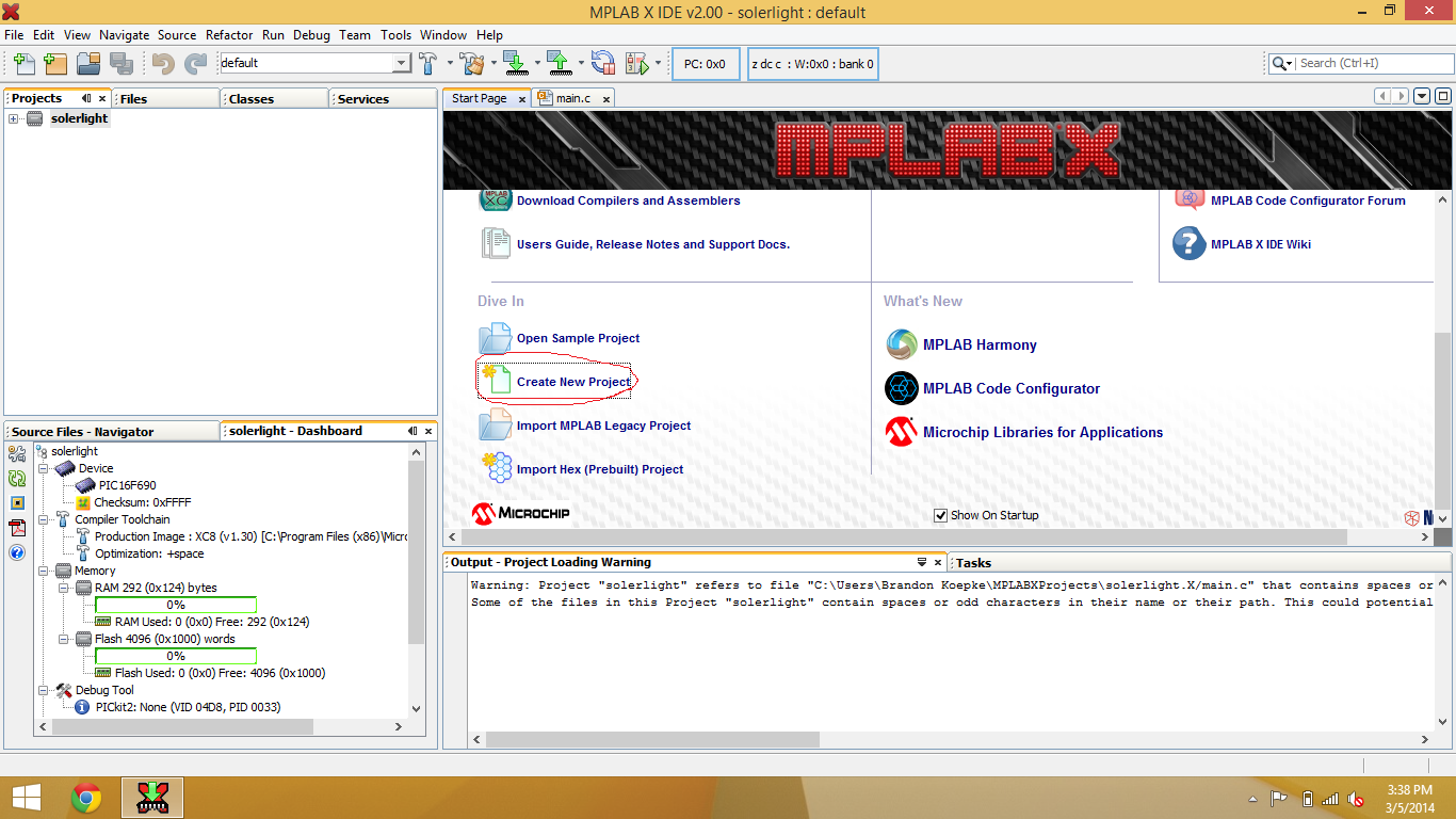
- Open MPLAB X software
- Go to create new project
- Make new stand alone project
- Select the pic16f690 in devices
- Hit next
- Supported debug header, select none
- Select the PICkit3 in select tool
- Choose the XC8 compiler
- Make a project name
- Click finish
- If you need to change any of these parameters at any time go to file>project properties.
Programming the PIC
In this step we will be adding code to the PIC microcontroller to operate our circuit.
- Setting up Main.c
- This is where you will write/copy code to be loaded to your microcontroller.
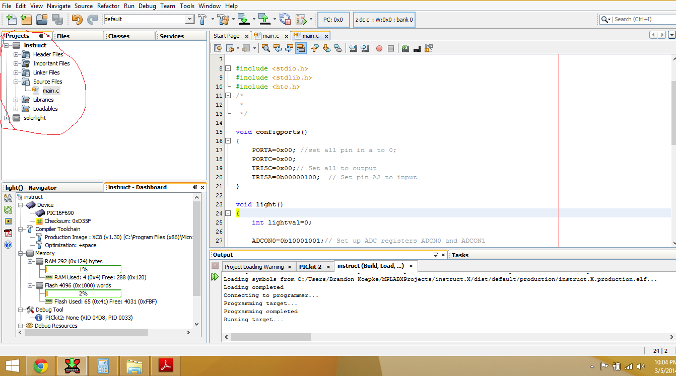
- In the projects file go to the project you would like to work on. EX: instruct
- Make sure that the project is set to the main project if you have multiple projects already.
- Right click on the project name then click on set as main project
- Right click on the project name, new>CMain file
- Name the file main
- Coding
- Replace your main.c code with the code attached or make your own.
Downloads
Exciting the Code of the Sensor
In this step we will be adding code to the PIC microcontroller to operate our circuit.
- To run the project
- Run > run main project
- This will not compile and download if there is an error with your code or if there is a problem connecting to the PICkit.
- Run > run main project
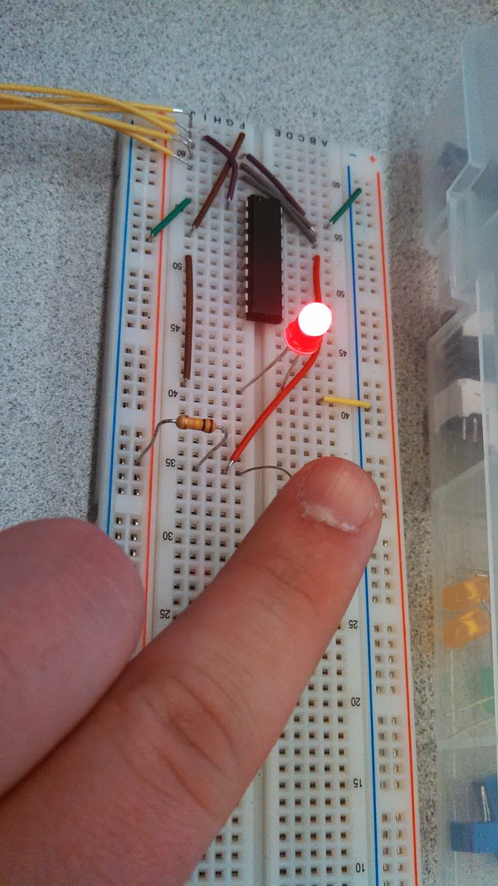
- Test you code
- Turn the lights on and off or cover the photo resistor with your finger to turn the LED on and off.
You have created your first integrated circuit using the PIC microcontolller. Now that you have a general knowledge on coding a mircocontler, try making projects of your own. Integrated circuits using CMOS, BJT, and diodes will be a great place to start making more complicated designs. Microcontollers are in just about everything from shoes to cars to video game controllers to clocks; the list is endless. So just remember to play around with the technology and have fun. Thank you for completing my inscrutable.