Light-Controlled Box
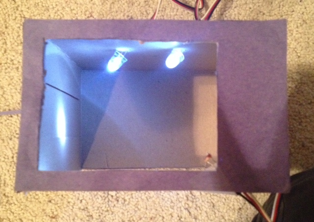
I came up with the idea of a smart device that would sense the natural light outside of a room and adjust the brightness of the lighting inside to maintain a constant brightness. Also, if it exceeded a certain brightness outside, it would lower a shade over the window. For this project, I made a model of this, using a small box to represent a room.
In order to make this device, you will need the following materials:
- Arduino Uno microcontroller
- breadboard
- jumper cables
- servo cables
- 2 LEDs
- photoresistor
- servo motor
- 2 470 Ω resistors
- 1 10 kΩ resistor
- small box
- paper
- small piece of cloth
In order to make this device, you will need the following materials:
- Arduino Uno microcontroller
- breadboard
- jumper cables
- servo cables
- 2 LEDs
- photoresistor
- servo motor
- 2 470 Ω resistors
- 1 10 kΩ resistor
- small box
- paper
- small piece of cloth
Connect the LEDs
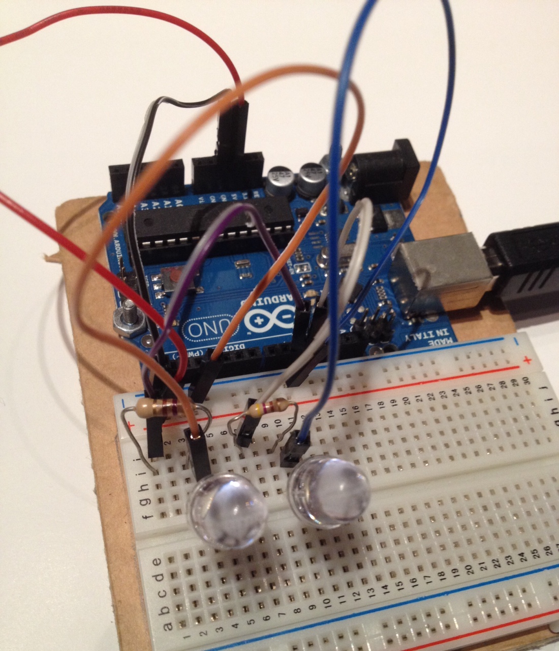
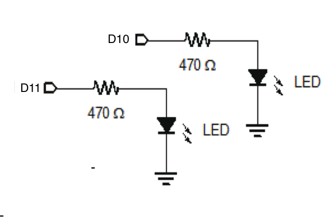
Set up your two LEDs on the breadboard following the circuit diagram in the second photo. First, run jumper cables from the positive rail of your breadboard to the 5V pin and from the negative rail to ground. Connect the positive ends to 470Ω resistors and into digital pins 10 and 11. Then connect the negative ends to the negative rail on the breadboard. When you are finished, your breadboard should look something like the first photo.
Connect the Photoresistor
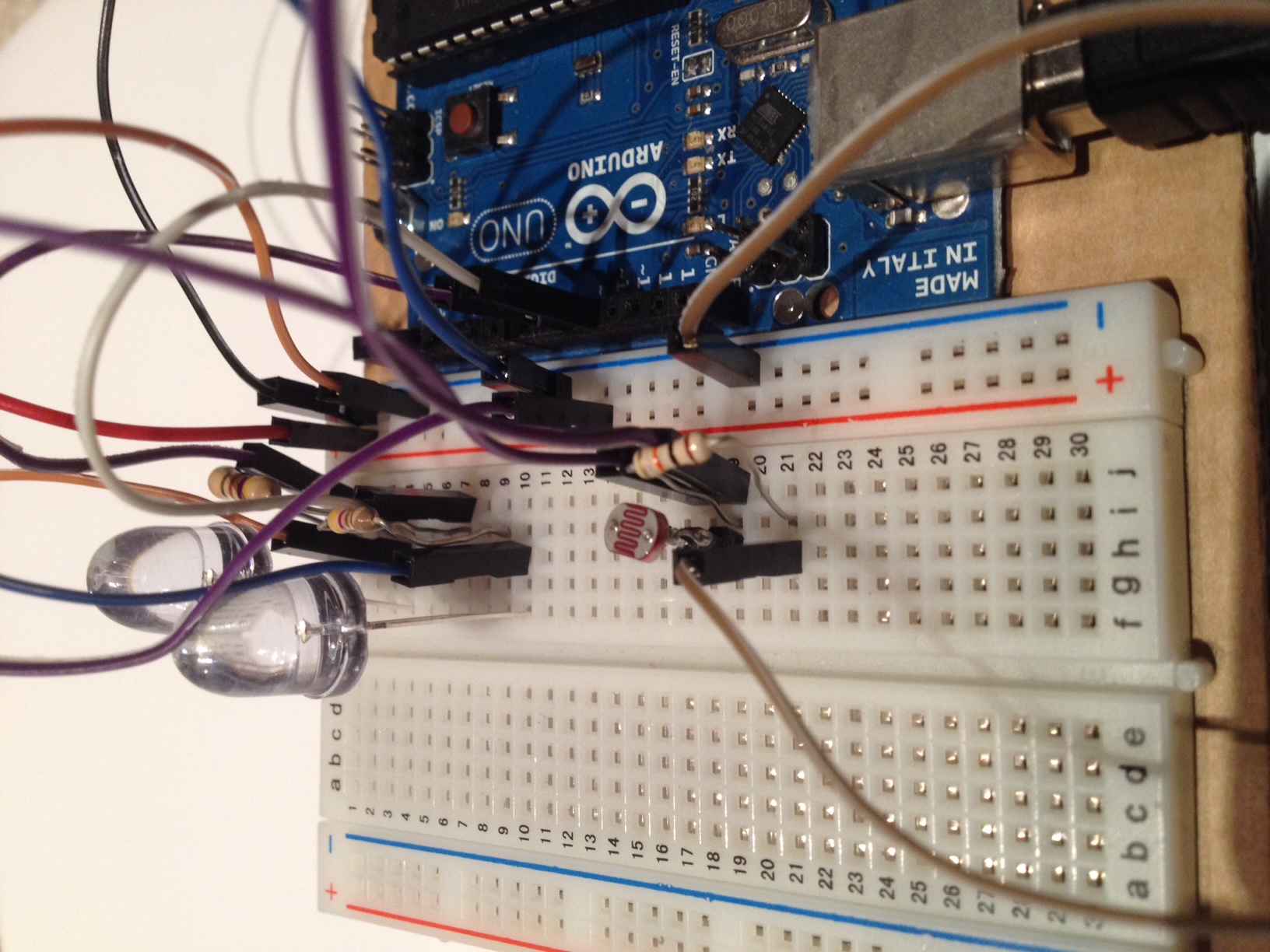
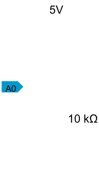
Now, add your photoresistor to the circuit. Connect one end to the positive rail of your breadboard, and the other end to analog pin 0 and a 10 kΩ resistor. Then connect the other end of the resistor into the negative rail, as show in the second photo.
Program the Arduino to Fade the LEDs
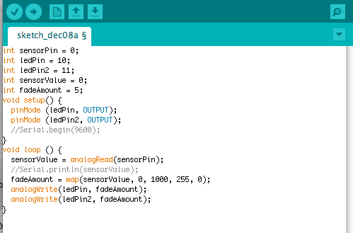
First, we will program the Arduino to take in an input from the photoresistor and dim or brighten the LEDs accordingly. Enter the following code:
int sensorPin = 0; //connects the photoresistor to pin A0
int ledPin = 10; //connects the LEDs to pins D10 and D11
int ledPin2 = 11;
int sensorValue = 0;
int fadeAmount = 5;
void setup() {
pinMode (ledPin, OUTPUT); //declares pins D10 and D11 as outputs
pinMode (ledPin2, OUTPUT);
//Serial.begin(9600);
}
void loop () {
sensorValue = analogRead(sensorPin); //reads the input of the photoresistor
//Serial.println(sensorValue);
fadeAmount = map(sensorValue, 0, 1000, 500, 0); //maps the input of the photoresistor to a corresponding brightness
analogWrite(ledPin, fadeAmount); //brightens or dims the LEDs according the the photoresistor input
analogWrite(ledPin2, fadeAmount);
}
You can map the input of your photoresistor by uncommenting the following two lines in your code:
Serial.begin(9600);
Serial.println(sensorValue);
Then, open the serial monitor and expose your photoresistor to various amounts of light. Decide on the range that you would like to use, and enter the values in the following line:
fadeAmount = map(sensorValue, [lower value], [upper value], 500, 0);
Connect the Servo
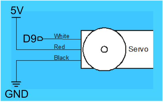
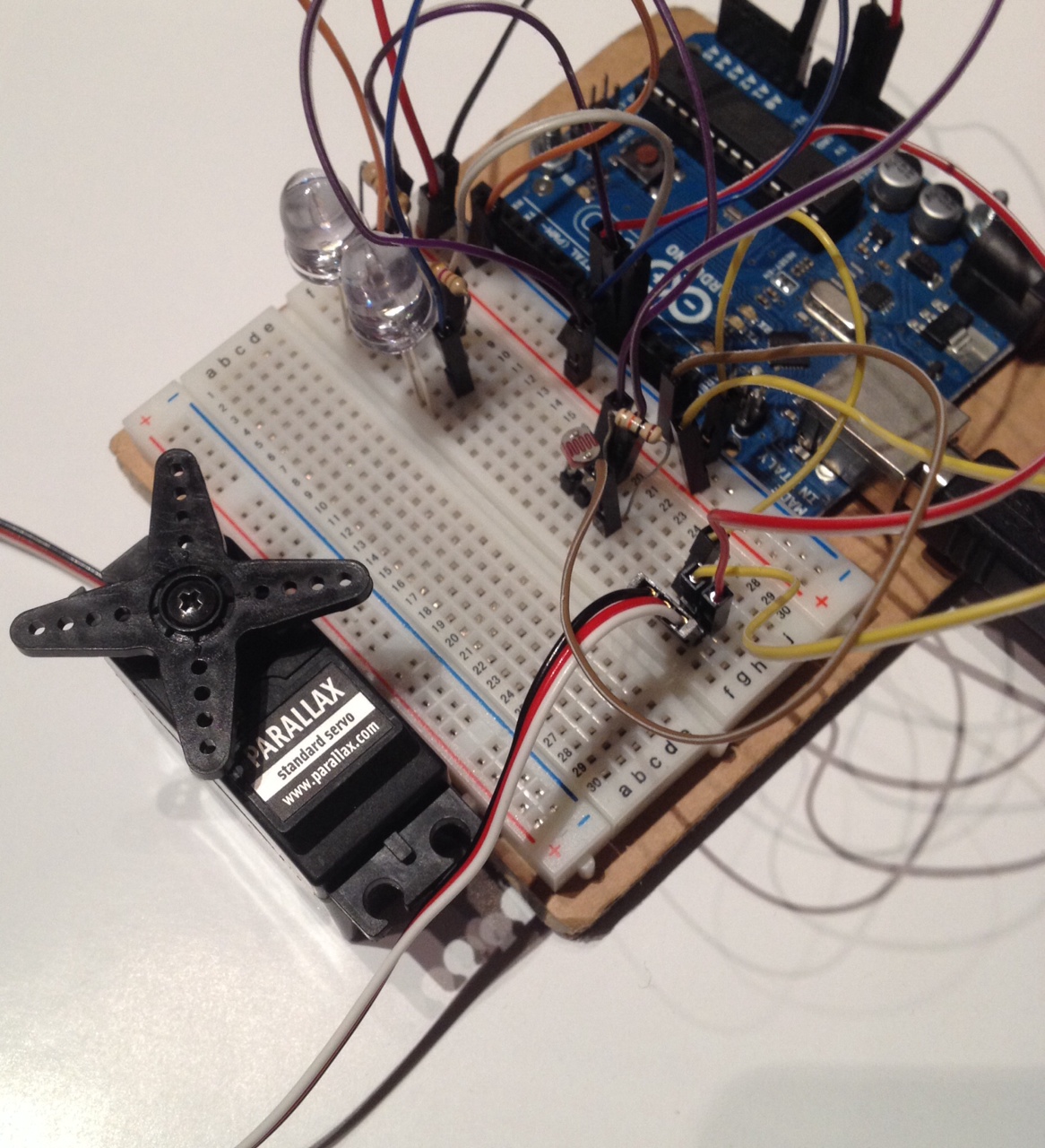
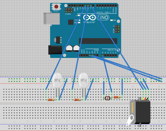
Now that we have the LEDs working, add the servo to your circuit. Connect the white wire to digital pin 9, the red wire to the positive rail (5V), and the black wire to the negative rail (GND). Your completed circuit should look something like the third photo.
Program the Servo to Turn at a Certain Brightness
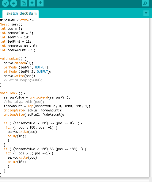
Add the following bolded lines to your code:
#include <Servo.h>
Servo servo;
int pos = 0;
int sensorPin = 0;
int ledPin = 10;
int ledPin2 = 11;
int sensorValue = 0;
int fadeAmount = 5;
void setup() {
servo.attach(9); //connects servo to pin 9
pinMode (ledPin, OUTPUT);
pinMode (ledPin2, OUTPUT);
servo.write(pos);
//Serial.begin(9600);
}
void loop () {
sensorValue = analogRead(sensorPin);
//Serial.println(pos);
fadeAmount = map(sensorValue, 0, 1000, 500, 0); //maps input
analogWrite(ledPin, fadeAmount); //adjusts brightness of LEDs based on input
analogWrite(ledPin2, fadeAmount);
if ( (sensorValue > 500) && (pos == 0) ) { //turns servo 180° in increments of 1° if input is greater than 500 and the position of the servo is at 0
for (; pos < 180; pos +=1) {
servo.write(pos);
delay(10);
}
}
if ( (sensorValue < 400) && (pos == 180) ) { //turns servo back 180° in increments of 1° if input is less than 400 and the position of the servo is at 180
for (; pos > 0; pos -=1) {
servo.write(pos);
delay(10);
}
}
}
This will be used to lower a shade if the brightness sensed by the photoresistor is greater than 500 and raise the shade if it is less than 400.
Set Up the LEDs and Photoresistor in the Box
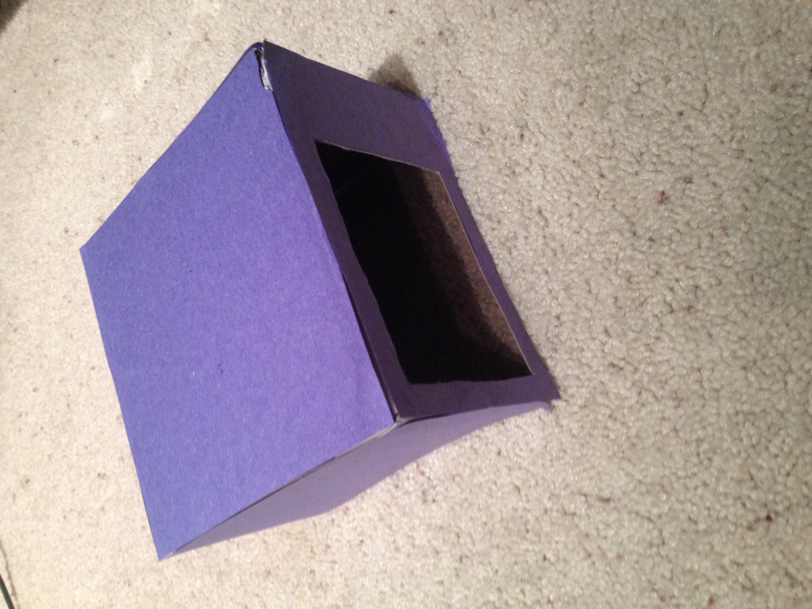
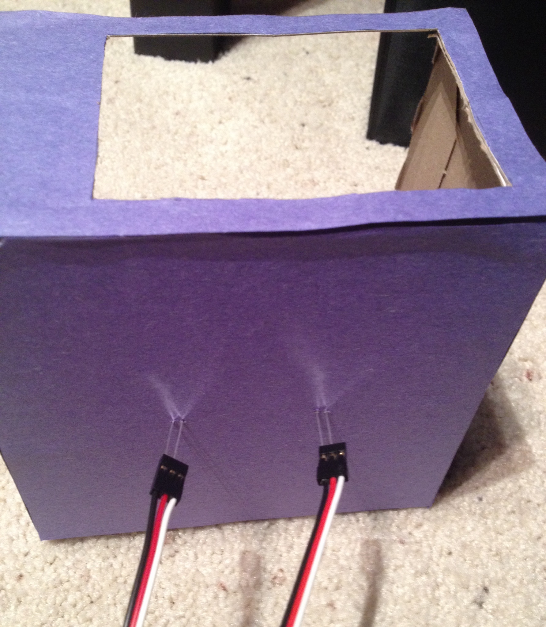
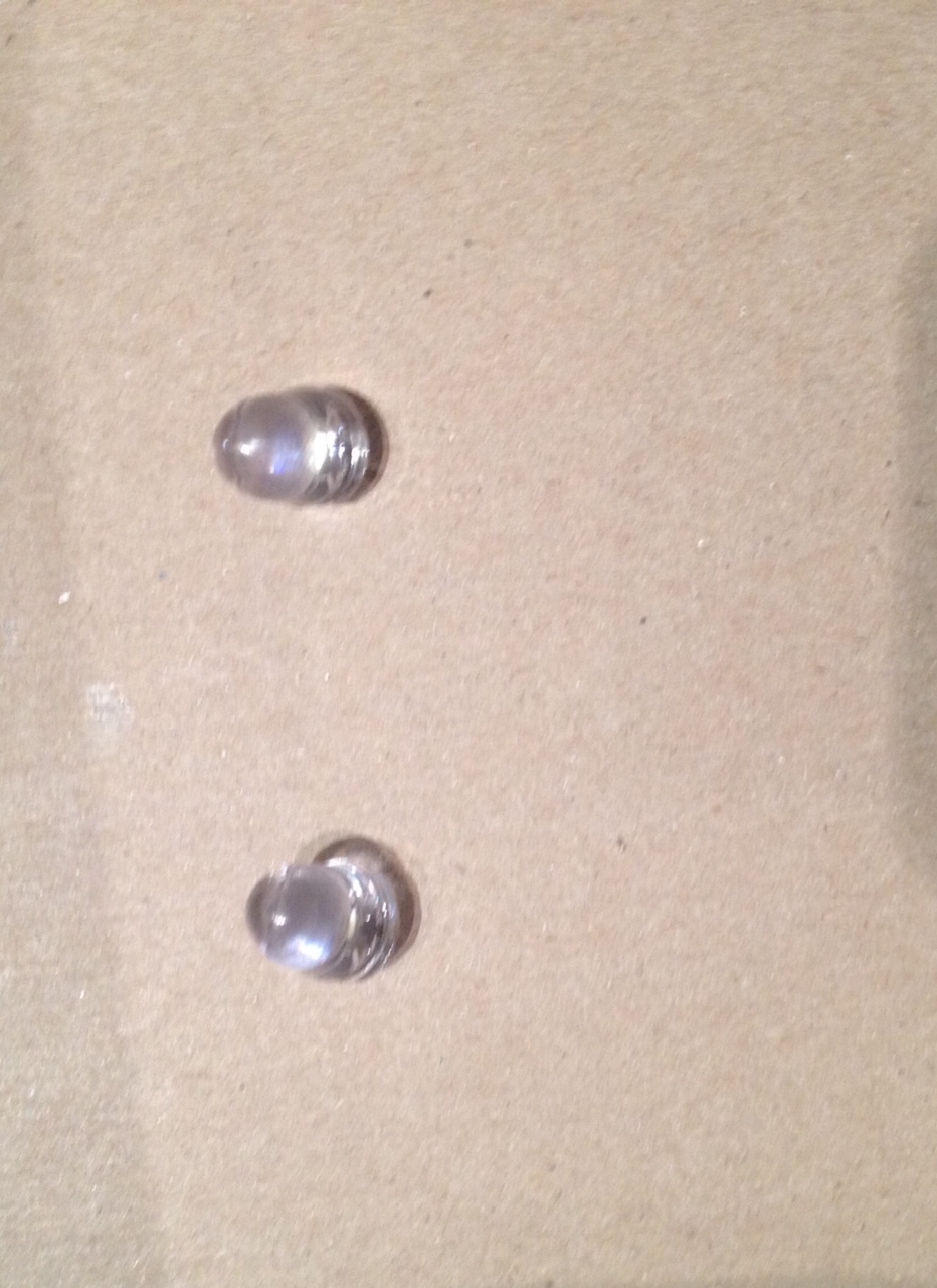
Find a small box and cut a hole in one side to represent a window. Then poke two pairs of small holes in the top of the box. Put the LEDs through the holes and put the photoresistor in a bottom corner of the "window." Connect them back to the breadboard using servo cables.
Set Up the Servo and Shade in the Box
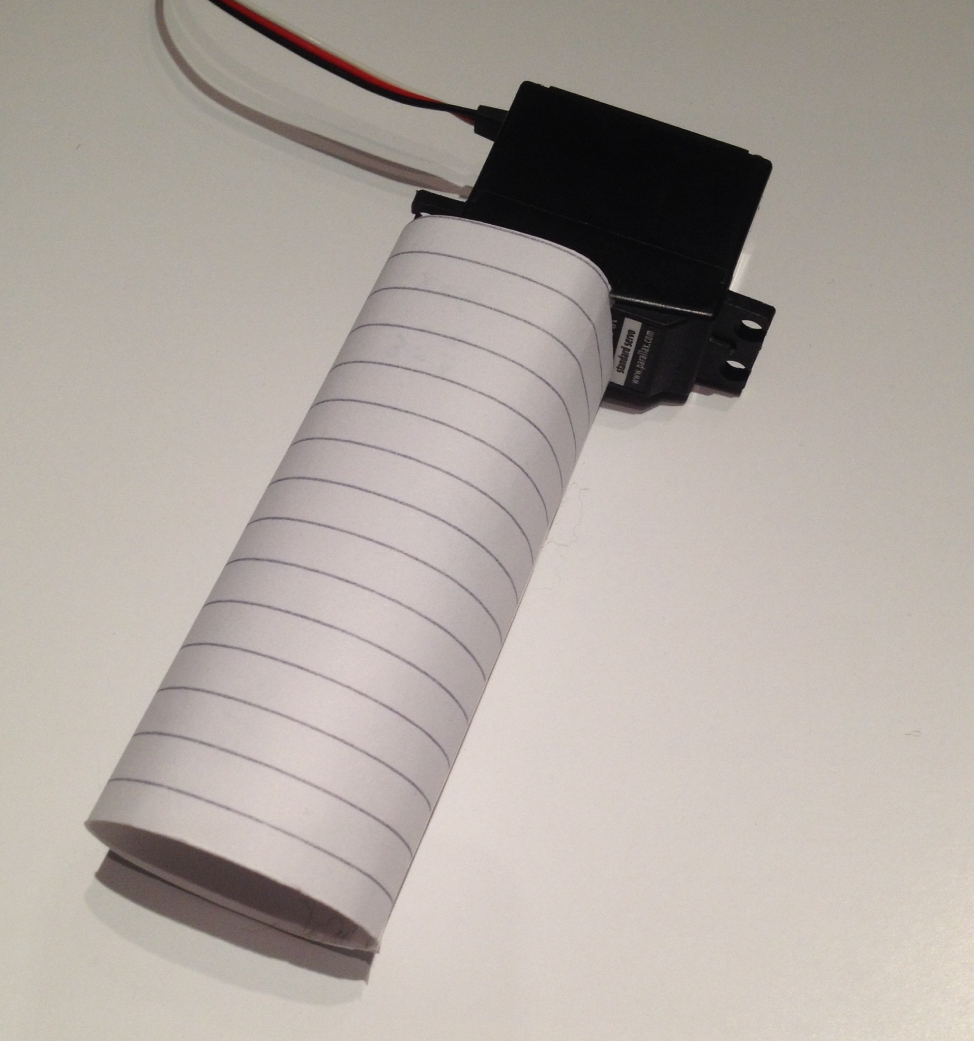
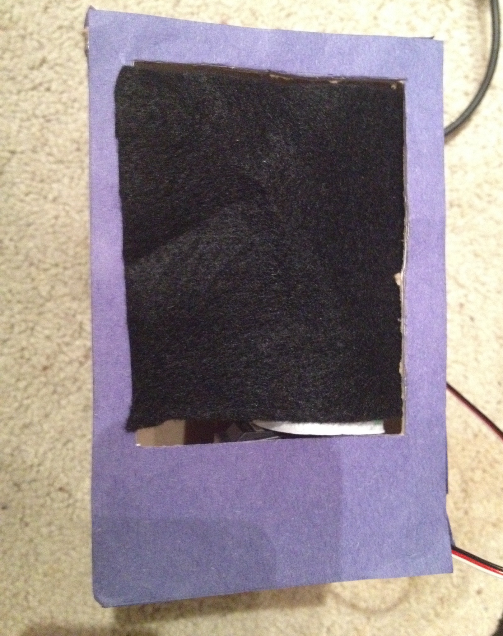
For the last part of this project, we need to set up a window shade. First, cut a small piece of cloth in the shape of your window. Then roll a small piece of paper into a tube that will fit around your servo. This will function as a "curtain rod." Attach the servo to the inside of the box, next to the window. With the servo rotated 180° in the "lowered" position, tape the cloth to the rod.