Upcycled Alarm Clock Smart Light
by theredbryophyte in Circuits > Raspberry Pi
8421 Views, 59 Favorites, 0 Comments
Upcycled Alarm Clock Smart Light
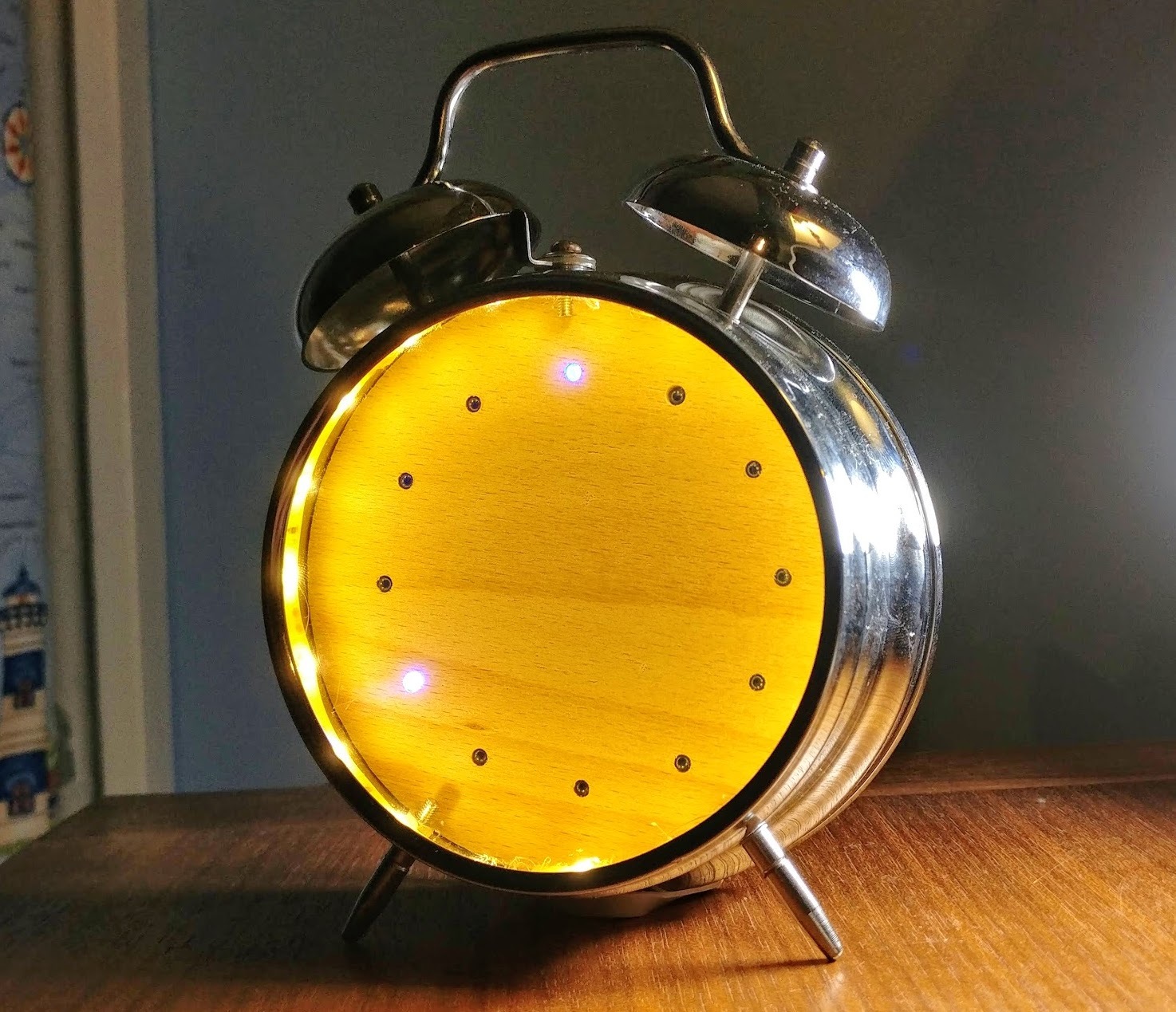
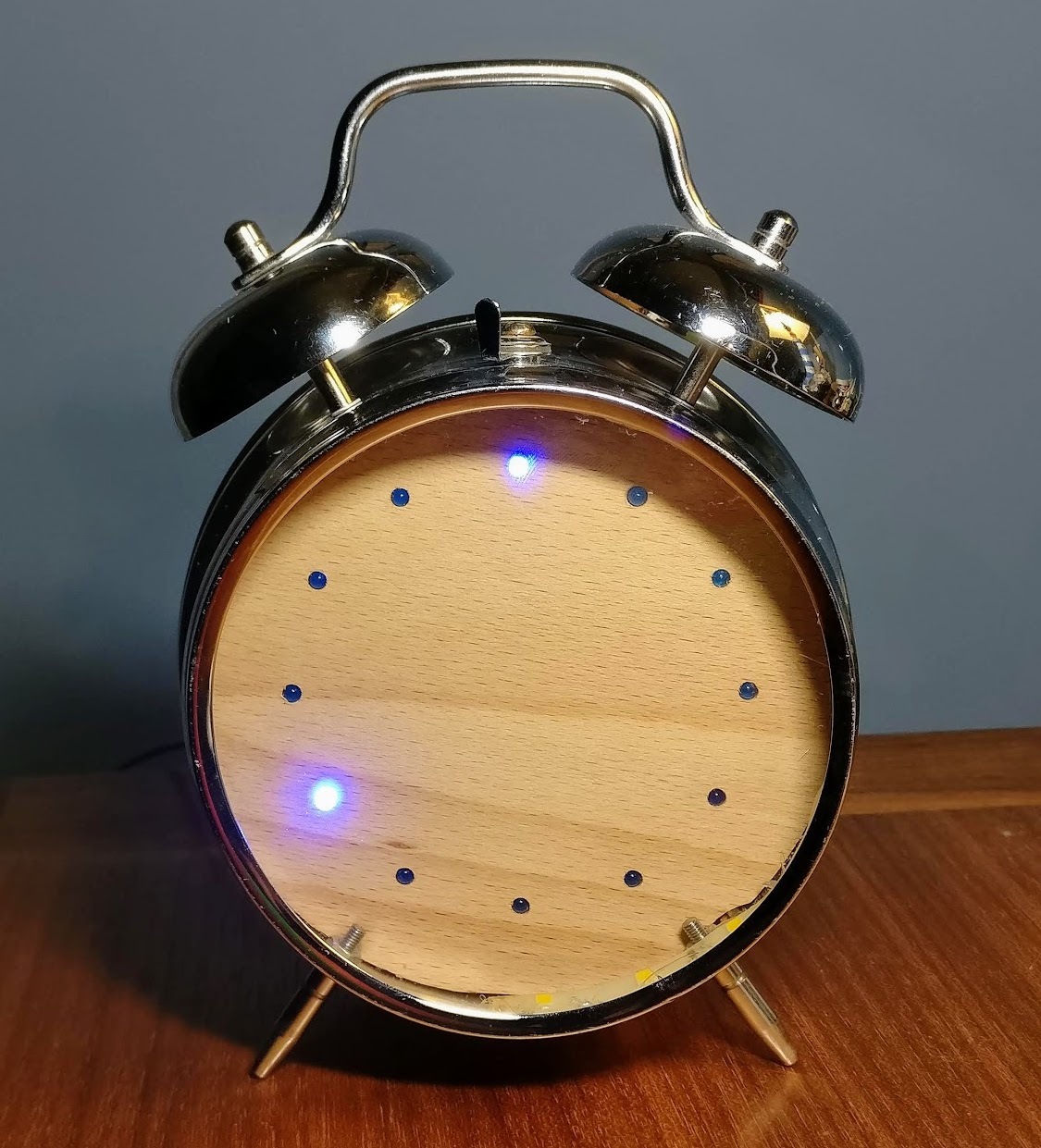
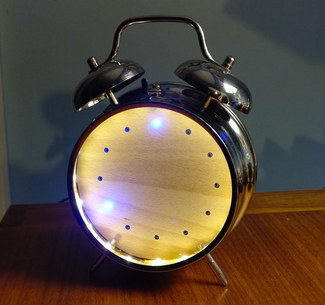
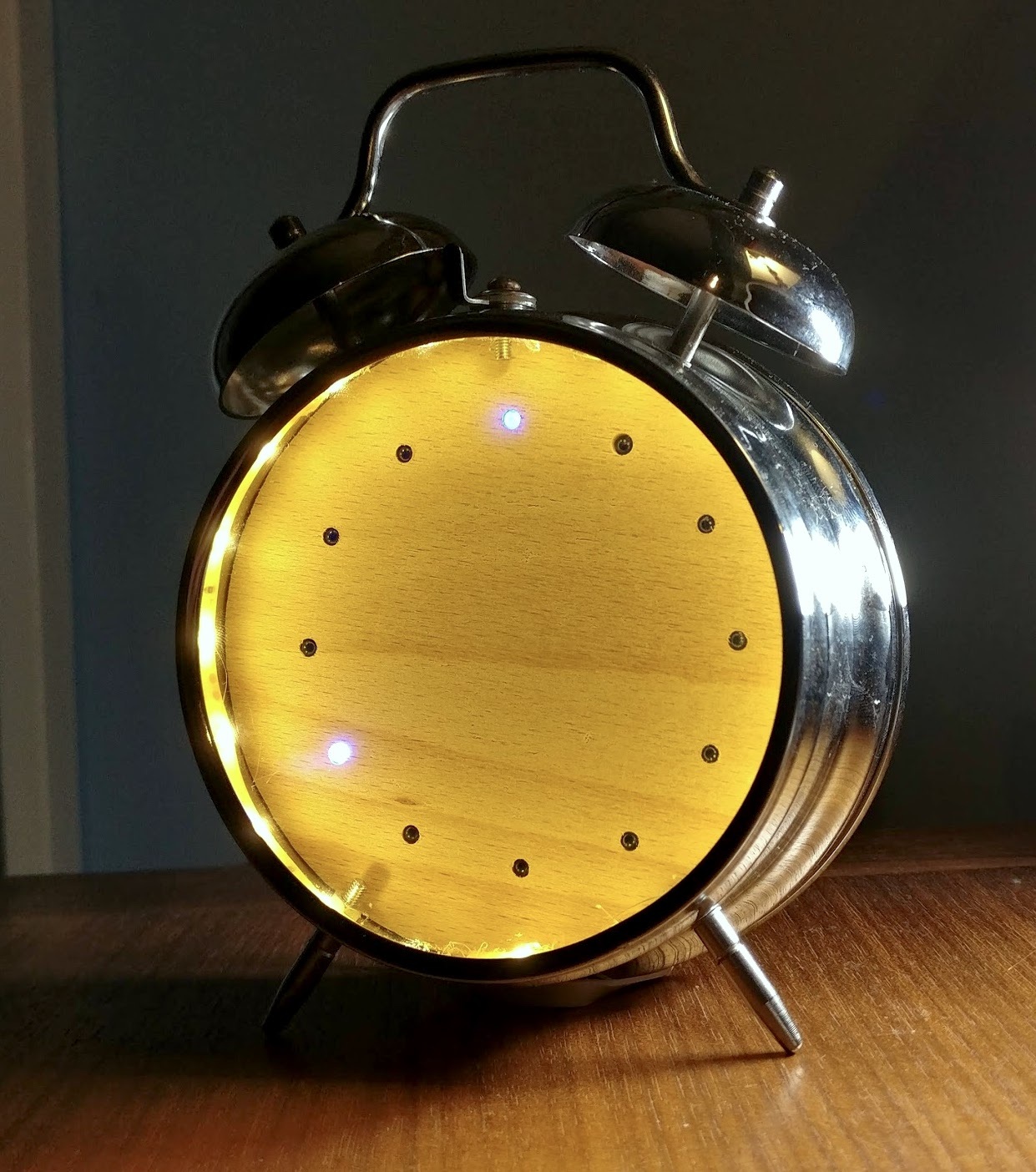
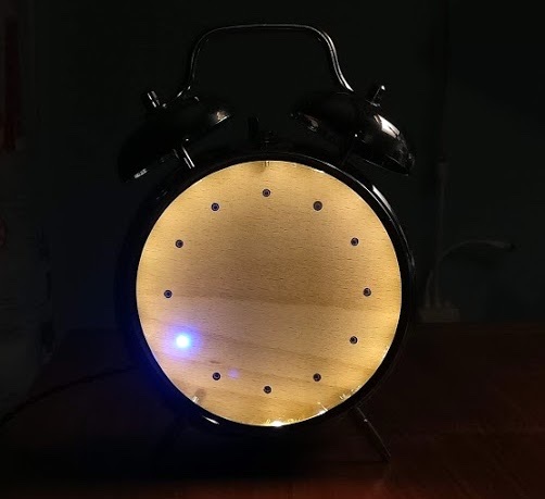
In this project I upcycle a completely broken wind-up alarm clock. The clock face is replaced by 12 LEDs, illuminated by an LED strip around the rim of the clock. The 12 LEDs tell the time and the LED strip is programmed to act as an alarm, turning up to full brightness at the set time. Everything is controlled by a Raspberry Pi Zero allowing for countless integration and expansion possibilities such as automatically synchronising the light alarm with your phone alarm or flashing the LEDs when you receive an email.
The project uses relatively cheap or reused components - the only thing I ended up buying was the voltage regulator. Everything else I happened to have lying around such as an off-cut of LED strip. This Instructable will guide you through how I gave a new life to my broken clock and hopefully might inspire you to upcycle something of your own.
Parts
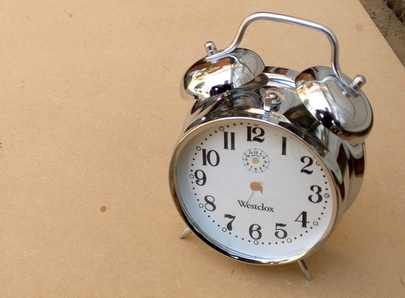
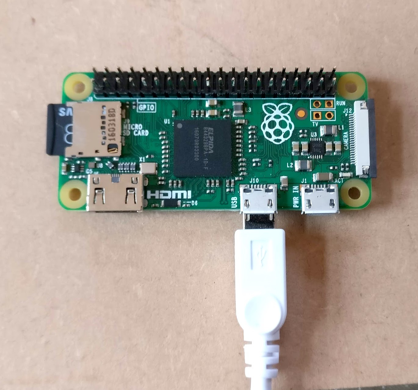
To control everything we're going to use a Raspberry Pi Zero as it's small, costs very little and can be connected to WiFi which means we don't need as real time clock and can therefore easily update the code over remotely from a laptop. Unless you have a Pi Zero W, we'll connect to a WiFi network using a USB WiFi dongle.
Here is a list of the parts I used but most things can be swapped out for suitable alternatives. For example instead of a Raspberry Pi you could use an Arduino with a real time clock to control the project.
Parts used
- An old alarm clock
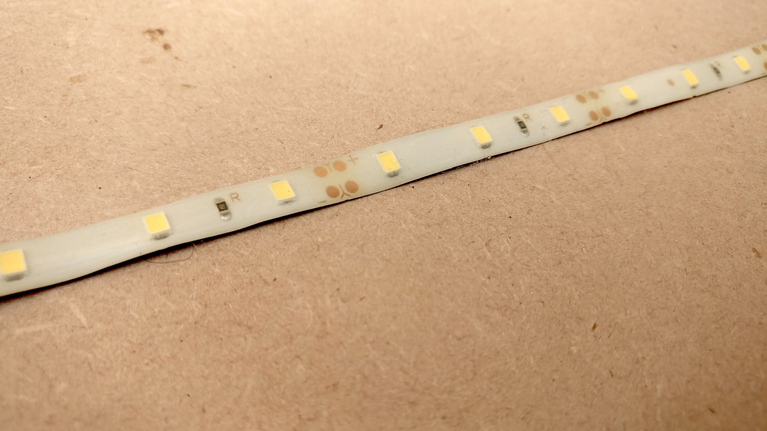
- 30cm of warm white LED strip
- 1x Raspberry Pi Zero + micro SD card
- 1x USB WiFi dongle + micro USB to USB converter
- 12x LEDs
- 12x 330ohm resistors (use higher if you want dimmer LEDs)
- 1x TIP31a (or other npn power transistor or MOSFET)
- 1x 1k resistor
- 1x LM2596 DC-DC adjustable buck converter (steps down 12V for 5V for the Raspberry Pi)
- 1x 12v power supply (+ way of getting in into your project)
- 10cm x 10cm of wood for the clock face (should be suitably thin to mount your LEDs in)
- Various pieces of different colour wire
Useful things to have
- Soldering iron + solder
- Hot glue
- Multimeter
- Breadboard
- Female header pins
- Micro SD card reader or converter
- A computer
- Mini HDMI adaptor + HDMI screen if you want to use the Pi's desktop environment
Setting Up the Raspberry Pi
Operating System
Because the Raspberry Pi won't be connected to a screen, I chose to use Raspbian Buster Lite which doesn't come with a desktop environment. If you are newer to Raspberry Pi you may want to stick to the standard Raspbian Buster which comes with a desktop. If you're not sure how to install your operating system, this is a great resource. Both operating systems can be downloaded from the Raspberry Pi website.
For the moment, power the Pi via its Micro USB power input. Also connect up the USB WiFi dongle.
Talking to the Raspberry Pi
Once everything is packaged up it's quite hard to access the Pi if you want to change the code etc. Using SSH lets use connect to the Pi and control it from another computer. This isn't turned on by default but we can do by simply making a folder called ssh in the boot partition of your SD card. If you've already logged into your Pi you can also do this by typing sudo raspi-config in the Terminal and navigating to Interfacing Options > SSH and choosing Yes to enable it.
Now you can connect to your Pi on another computer. On Mac or Linux you can use your terminal application but on most versions of Windows you'll have to install a SSH client such as PuTTY. Connect to the Pi by typing ssh pi@ where hostname is replaces with the hostname of IP address of your Pi. The default hostname is raspberrypi.local. It will ask you for a password which, if you haven't changed it yet, is raspberry.
Installing stuff needed
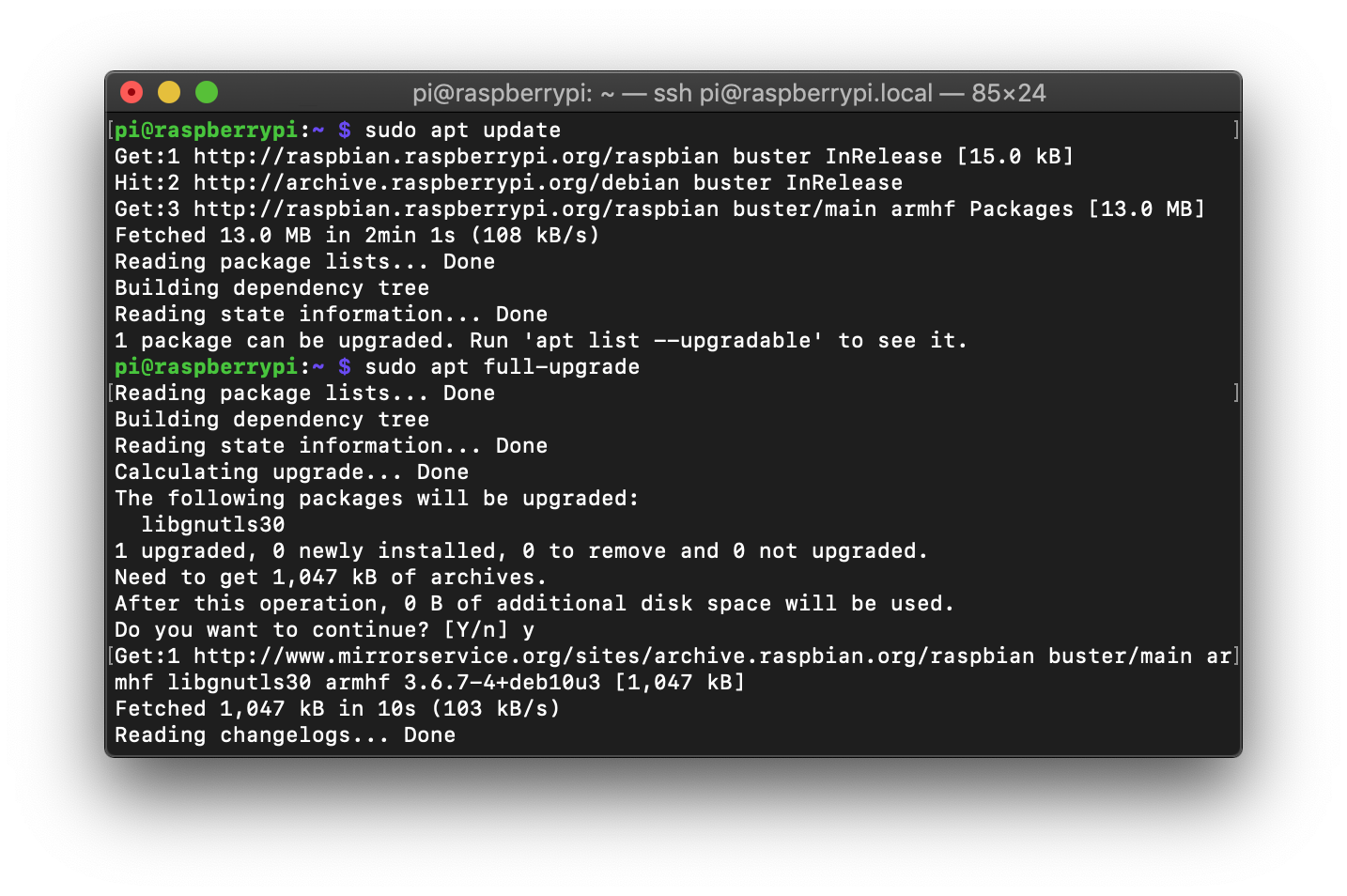
First make sure everything is up to date by running sudo apt update and then sudo apt full-upgrade.
To make sure what we need to control the GPIO pins on the Pi type sudo apt-get install python-rpi.gpio and sudo apt-get install python3-rpi.gpio. These should already be installed on the full version of Raspbian.
The code
Here's the code to download to get it all working. If you're using a desktop environment paste these in your Documents folder.
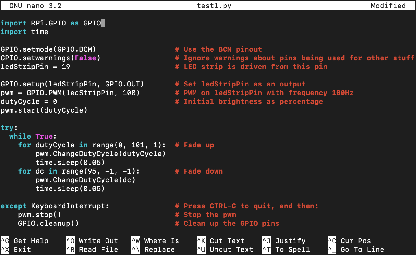
If you're using the command line of SSH, navigate to your home folder by typing cd ~/Documents and pressing enter. Make a new file called test1.py with nano test1.py. This will open the nano text editor where you can paste in the code of the downloaded test1.py file. CTRL-O and press enter to save the file and CTRL-X to quit the editor. Repeat the process for the remaining files.
Installing the LED Strip
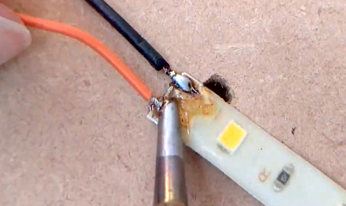
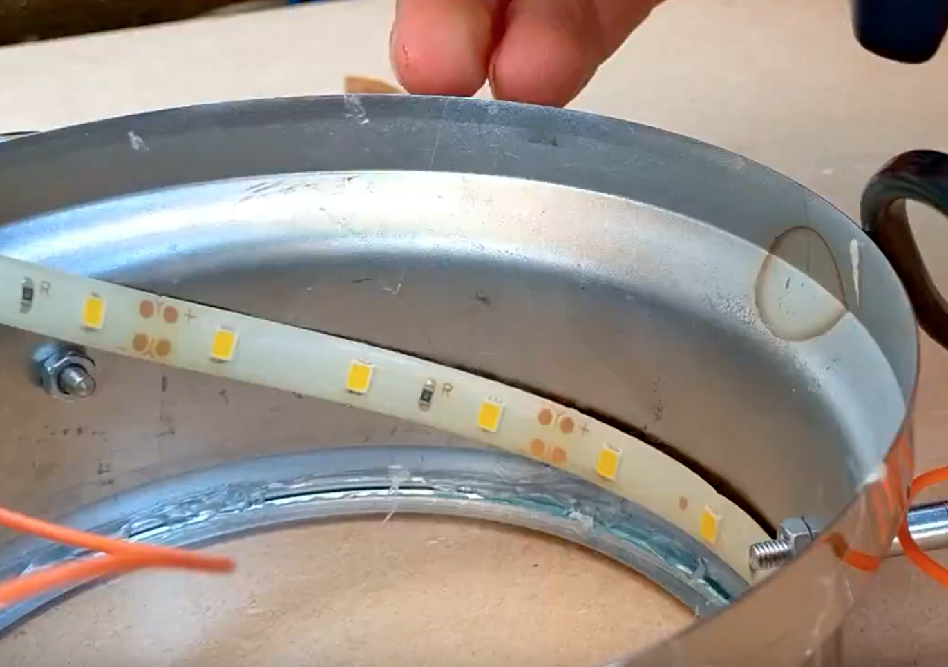
First pop the LED strip in the clock to see how much you'll need, mark this length and cut the strip at the next cut point as shown. It's a lot easier to solder wires to the strip before the strip gets stuck in place. This is a pretty good guide on how to do this but if you're unsure I'd just practice on the solder join on the piece you've just cut your strip from. Solder one wire to the positive solder point and one wire to the negative. Make sure you test your LED strip works before you stick it in your clock.
Since the LED strip I used had been used before it had lost its self adhesive backing so I had to use hot glue to fix the strip around the edge of the clock rim. If you have excess length, cover the point where the wires are attached. You may want to install the strip later on but I found it easier to have it tucked away in the clock.
Controlling the LED Strip
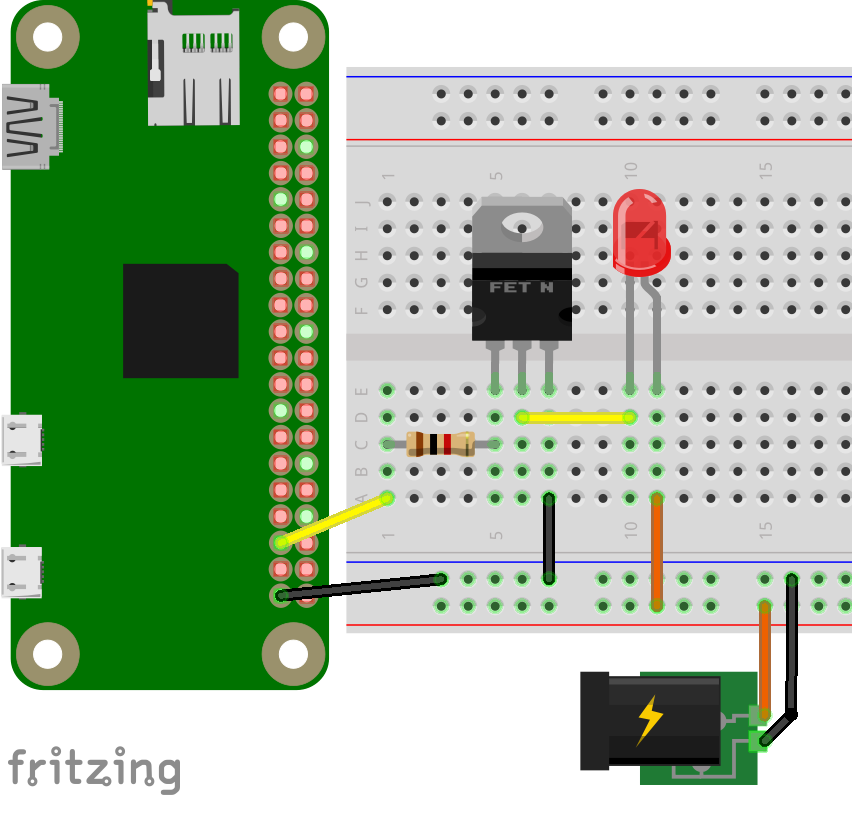
Connecting the LED strip
The LED strip runs on 12V so can't be powered from the Pi directly. In order to control them we'll be using a power transistor (eg TIP31a) connected up to the Pi as shown above. I'd recommend first checking this all works on a breadboard.
- Connect GPIO 19 to the base through a 1k resistor
- The emitter should be connected to GND
- Connect the collector to the negative terminal of the LED strip
- Connect the positive LED strip terminal to +12V
Testing
In the command line nagivate to your documents folder (cd ~/Documents) and type python test1.py and enter. You should see the LED strip increase and decrease in brightness. To quit the program press CTRL-C. You can edit the file (nano test1.py) to change the speed and brightnesses in the program.
import RPi.GPIO as GPIO
import time

GPIO.setmode(GPIO.BCM)                  # Use the BCM pinout
GPIO.setwarnings(False)                 # Ignore warnings about pins being used for other stuff
ledStripPin = 19                        # LED strip is driven from this pin

GPIO.setup(ledStripPin, GPIO.OUT)       # Set ledStripPin as an output
pwm = GPIO.PWM(ledStripPin, 100)        # PWM on ledStripPin with frequency 100Hz
dutyCycle = 0                           # Initial brightness as percentage
pwm.start(dutyCycle)

try:
  while True:
    for dutyCycle in range(0, 101, 1):  # Fade up
        pwm.ChangeDutyCycle(dutyCycle)
        time.sleep(0.05)
    for dc in range(95, -1, -1):        # Fade down
        pwm.ChangeDutyCycle(dc)
        time.sleep(0.05)

except KeyboardInterrupt:               # Press CTRL-C to quit, and then:
    pwm.stop()                          # Stop the pwm
    GPIO.cleanup()                      # Clean up the GPIO pins
Making the Clock Face
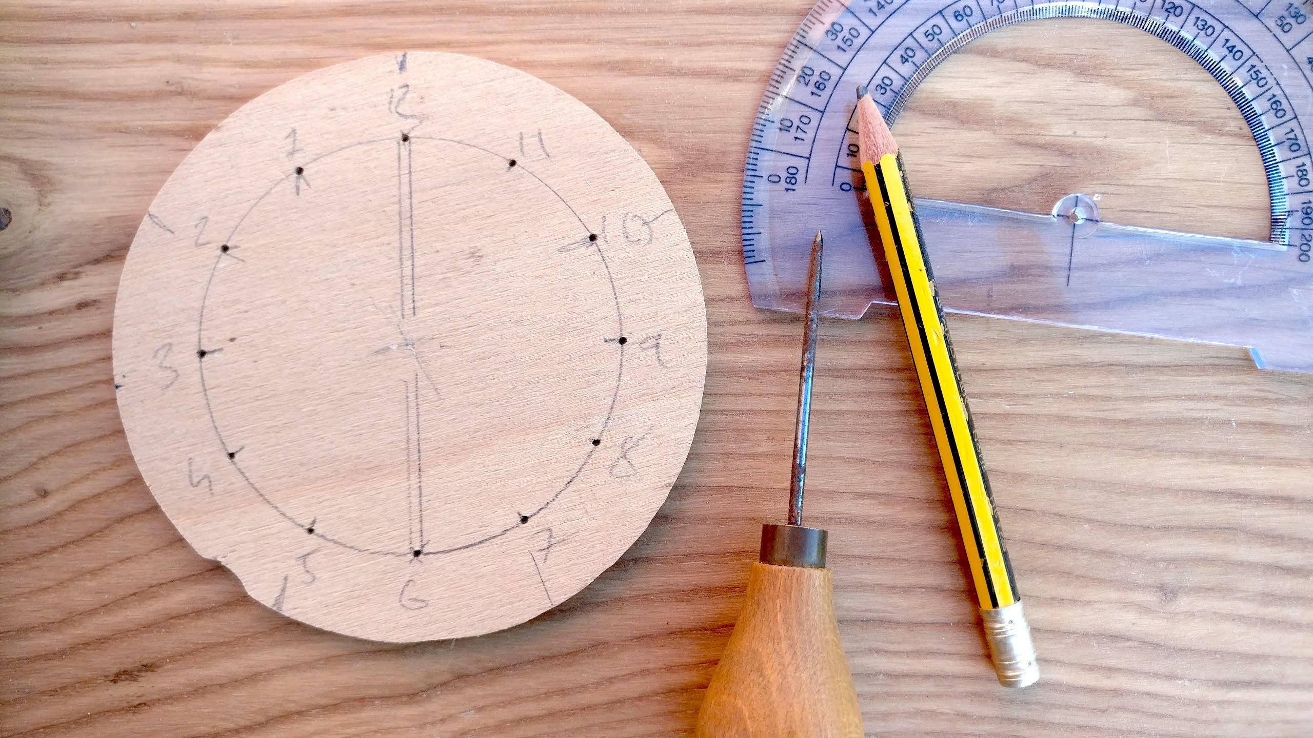
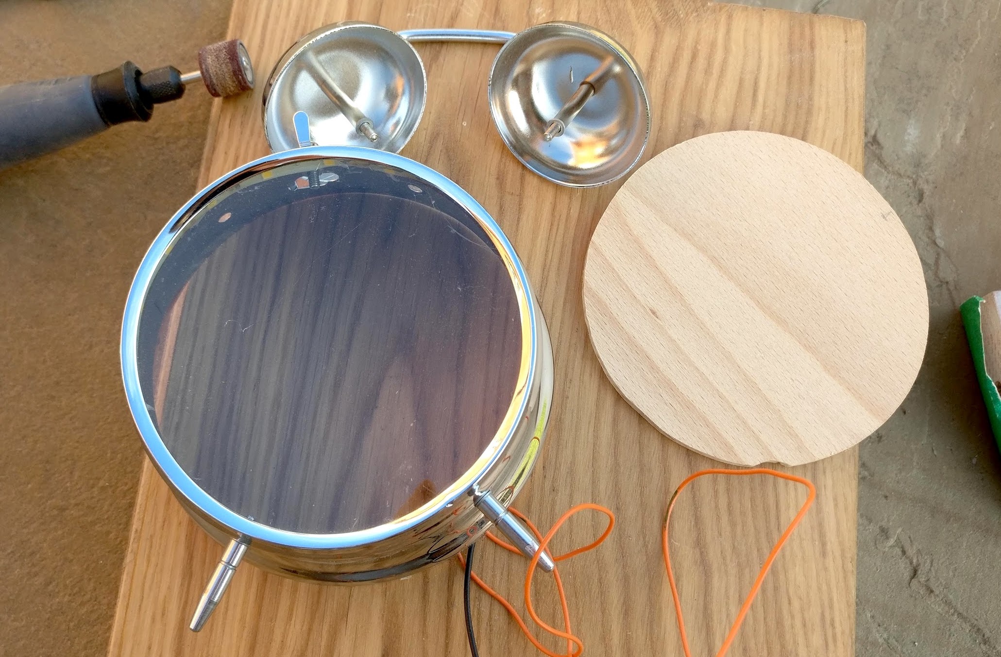
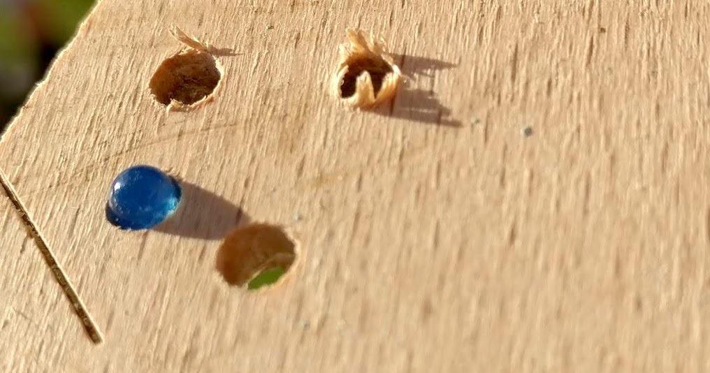
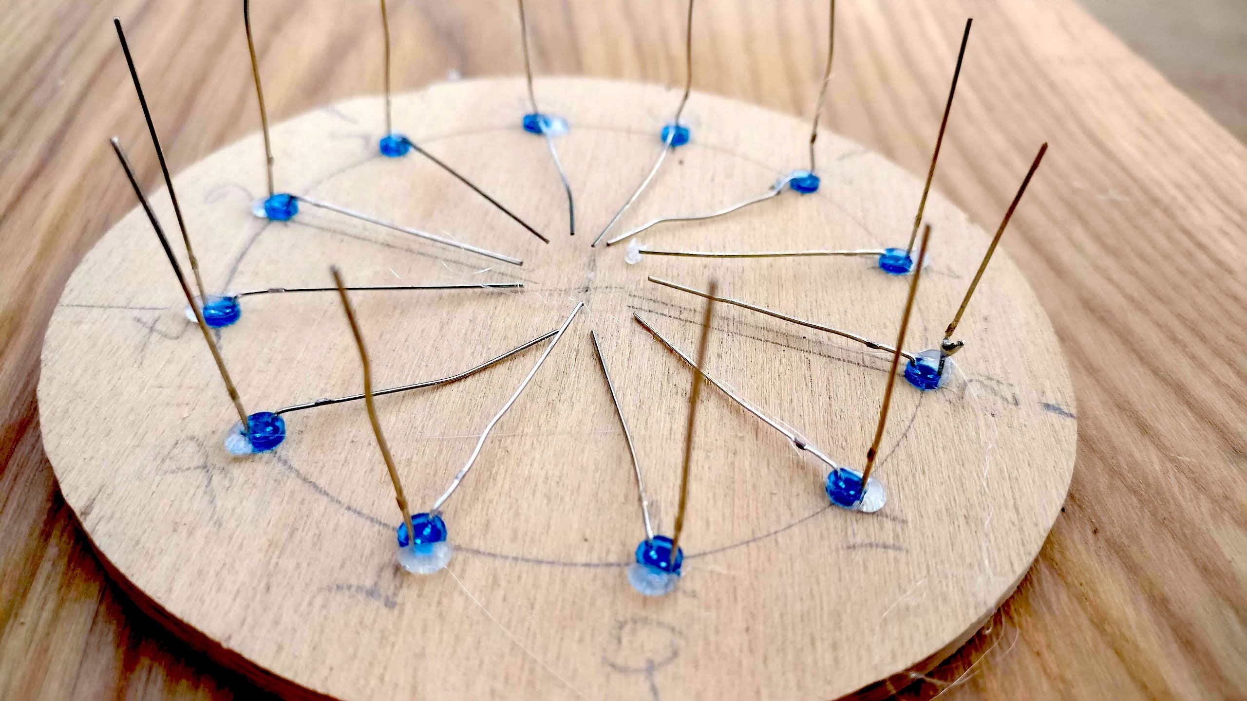
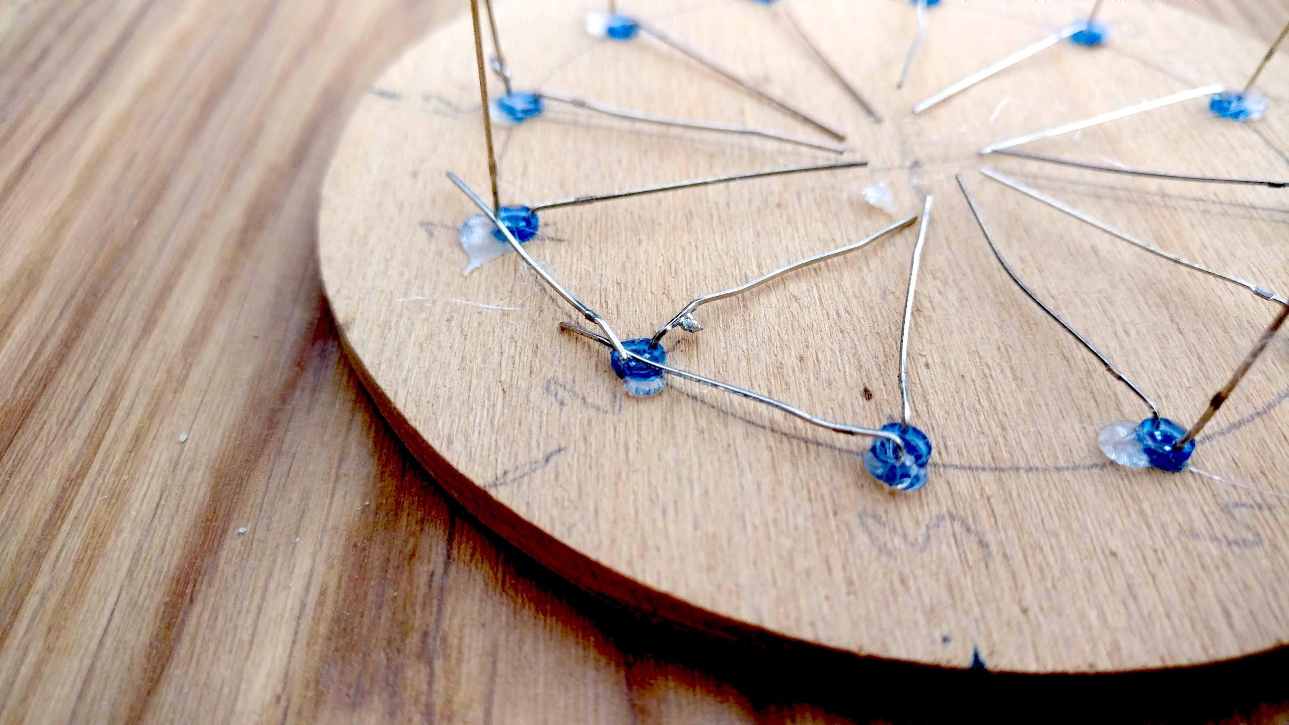
Cut the piece of wood for your clock face down to size so it fits in your clock. I made mine to rest at about 3cm from the front. Drill 12 holes the diameter of your LEDs (usually 3mm or 5mm) spaced 30 degrees from each other. Sand the front face down and apply a finish of your choice. From the back side place the LEDs so they point through to the front. I used hot glue to keep the LEDs in place with the positive terminal (longer wire) facing inwards. The size of my clock face meant I could solder all the negative terminals together (see above) so only one wire was needed to connect all 12 LEDs to GND. Next, solder a wire to each LED.
If you want to test this on a breadboard first remember to use a resistor (330ohm is pretty standard) in series with each LED before you connect it to one of the Pi GPIO pins. Play around with the value of resistor you use to get a brightness level you're happy with. A t-cobbler is really useful for breaking out the Pi's pins to a breadboard although you'll need to solder the header pins on for this. Use test2.py (run using python test2.py) but make sure you first edit the program and enter the Pi's GPIO pins you have used for each LED.
import RPi.GPIO as GPIO
import time

GPIO.setmode(GPIO.BCM)                  # Use the BCM pinout
GPIO.setwarnings(False)                 # Ignore warnings about pins being used for other stuff

# Replace one, two,... with corresponding pin number
hourPin = [one, two, three, four, five, six, seven, eight, nine, ten, eleven, twelve] # The pins the LEDs are connected to from 1-12

for i in range(0, 12):
    GPIO.setup(hourPin[i], GPIO.OUT)    # Set all the hourPins as outputs
    GPIO.output(hourPin[i], 0)          # Make sure all LEDs are off

try:
  while True:
    for i in range(0, 12)
        GPIO.output(hourPin[i], 1):
        time.sleep(0.05)
    for i in range(0, 12)
        GPIO.output(hourPin[i], 0):
        time.sleep(0.05)

except KeyboardInterrupt:               # Press CTRL-C to quit, and then:
    GPIO.cleanup()                      # Clean up the GPIO pins
Powering the Pi
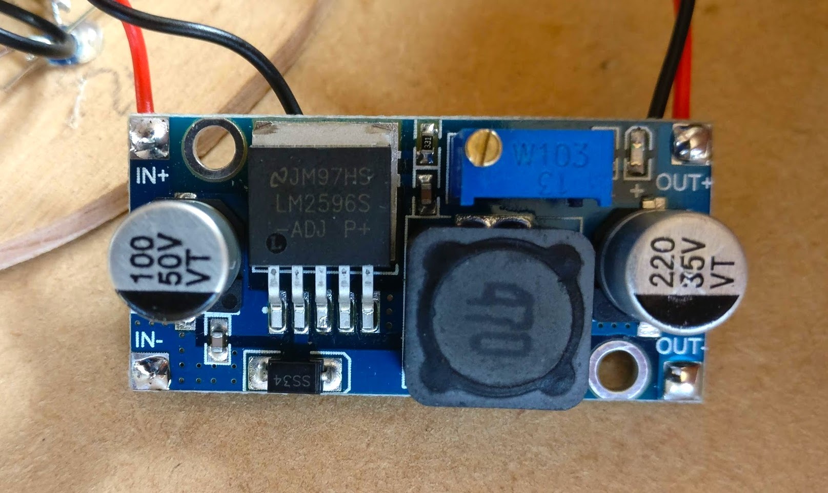
We need a easy way of getting 5V to the Pi Zero so we can get rid of the micro USB cable we've been using to power it so far. There are a number of solutions which step down 12V to 5V such as an LM7805 linear voltage regulator but these aren't very efficient so instead I opted to use the more efficient adjustable buck converter using the LM2596 chip. NB with this you'll have to twist the potentiometer until the output voltage is reduced to 5V as required so you'll need some way of measuring voltage.
Using the LM2596 is simple: connect the +12V to IN+, ground to IN-. The Pi can be connected directly to 5V by connecting OUT+ to one of the Pi's 5V pins but make sure you've have changed the output voltage to 5V before you do this or you will fry your Pi!
Complete the Circuit and Packaging
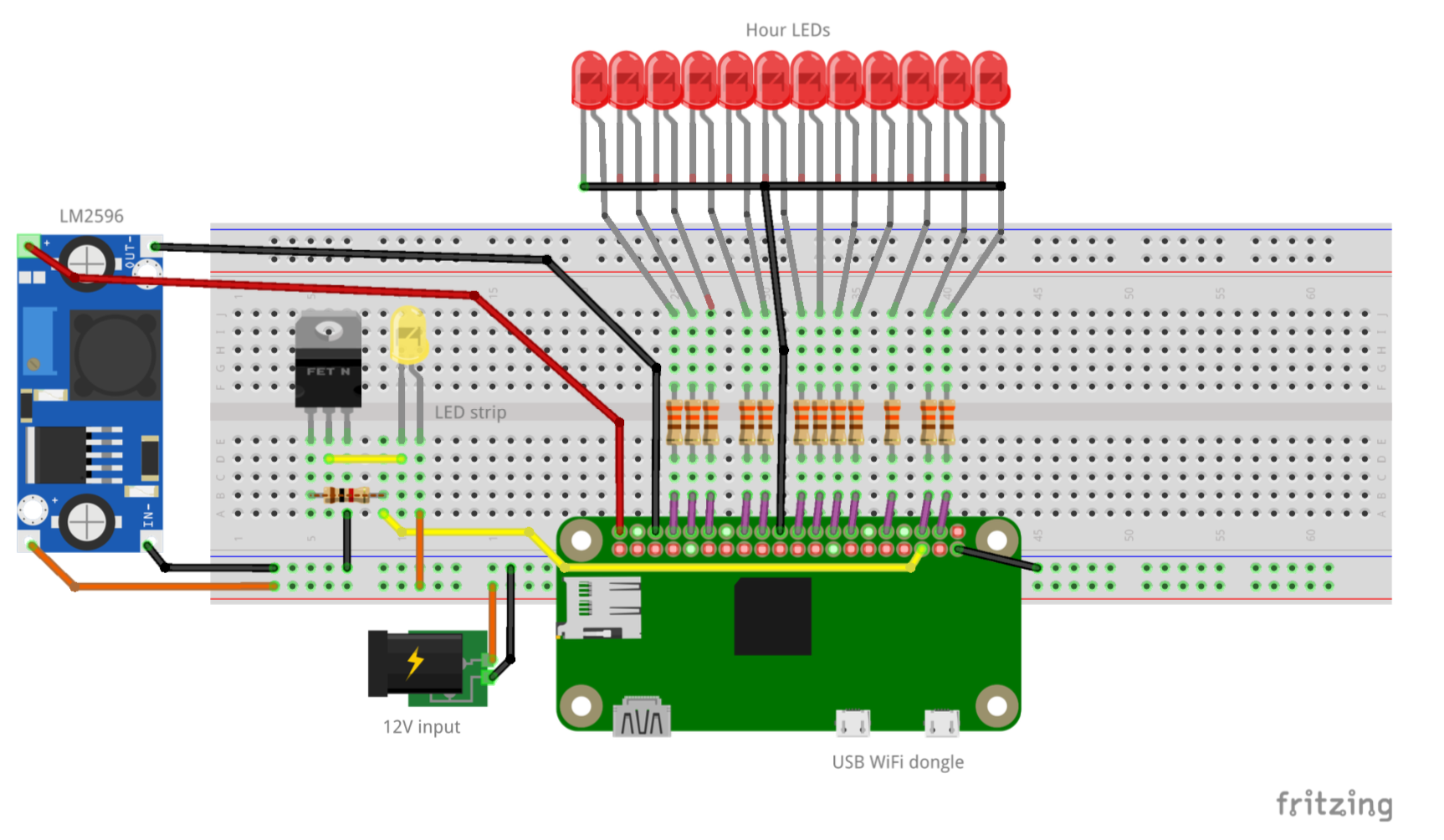
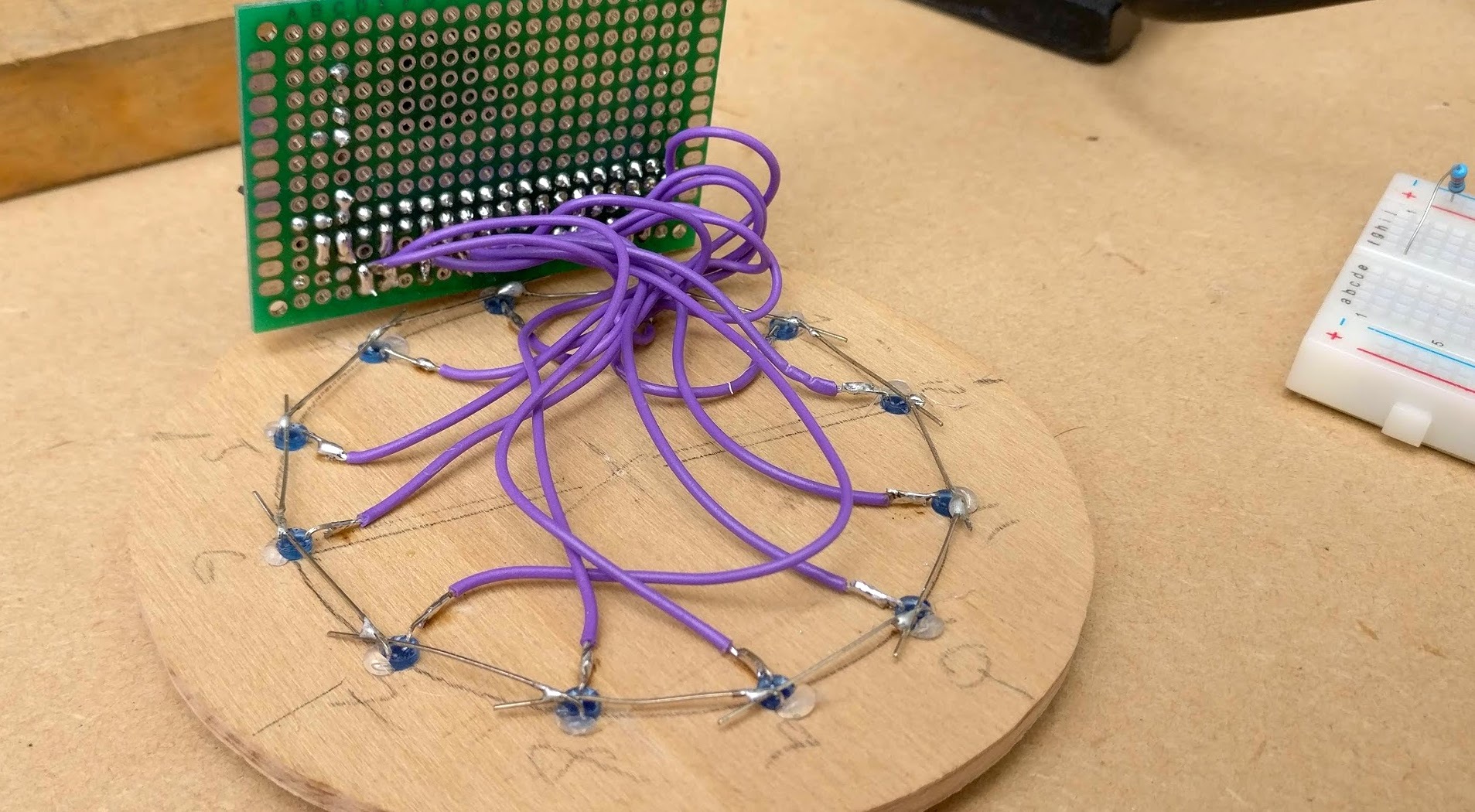
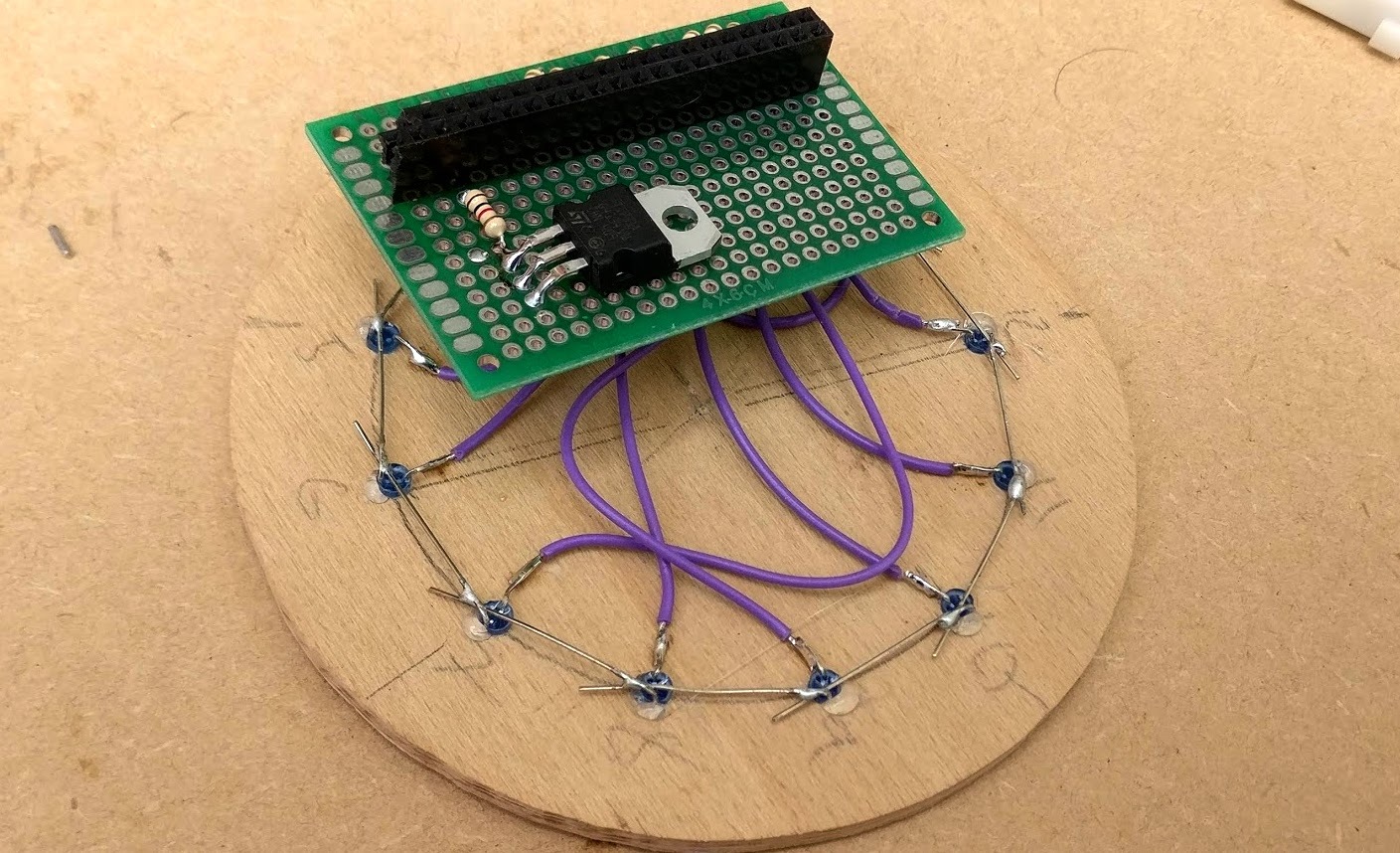
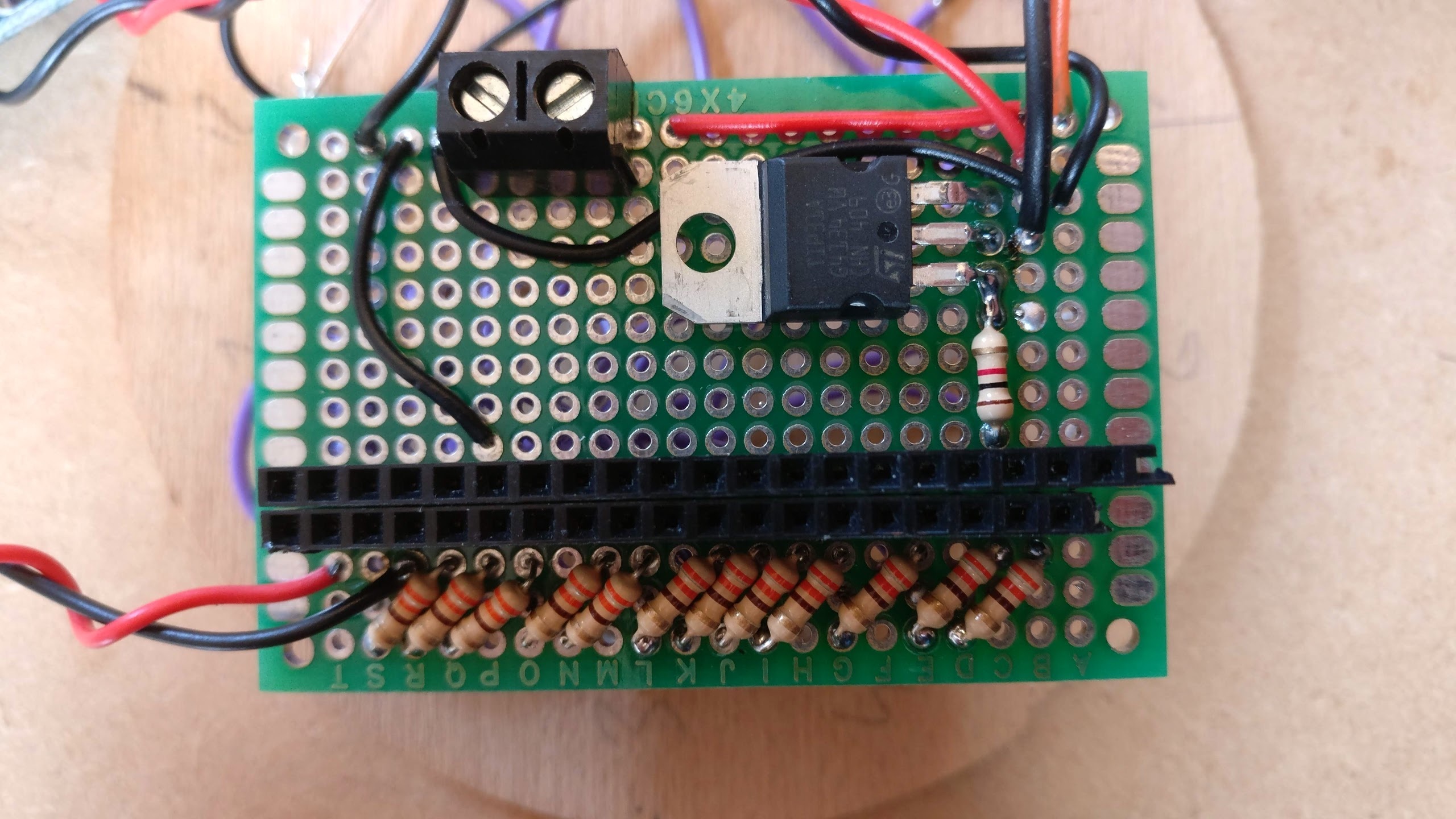
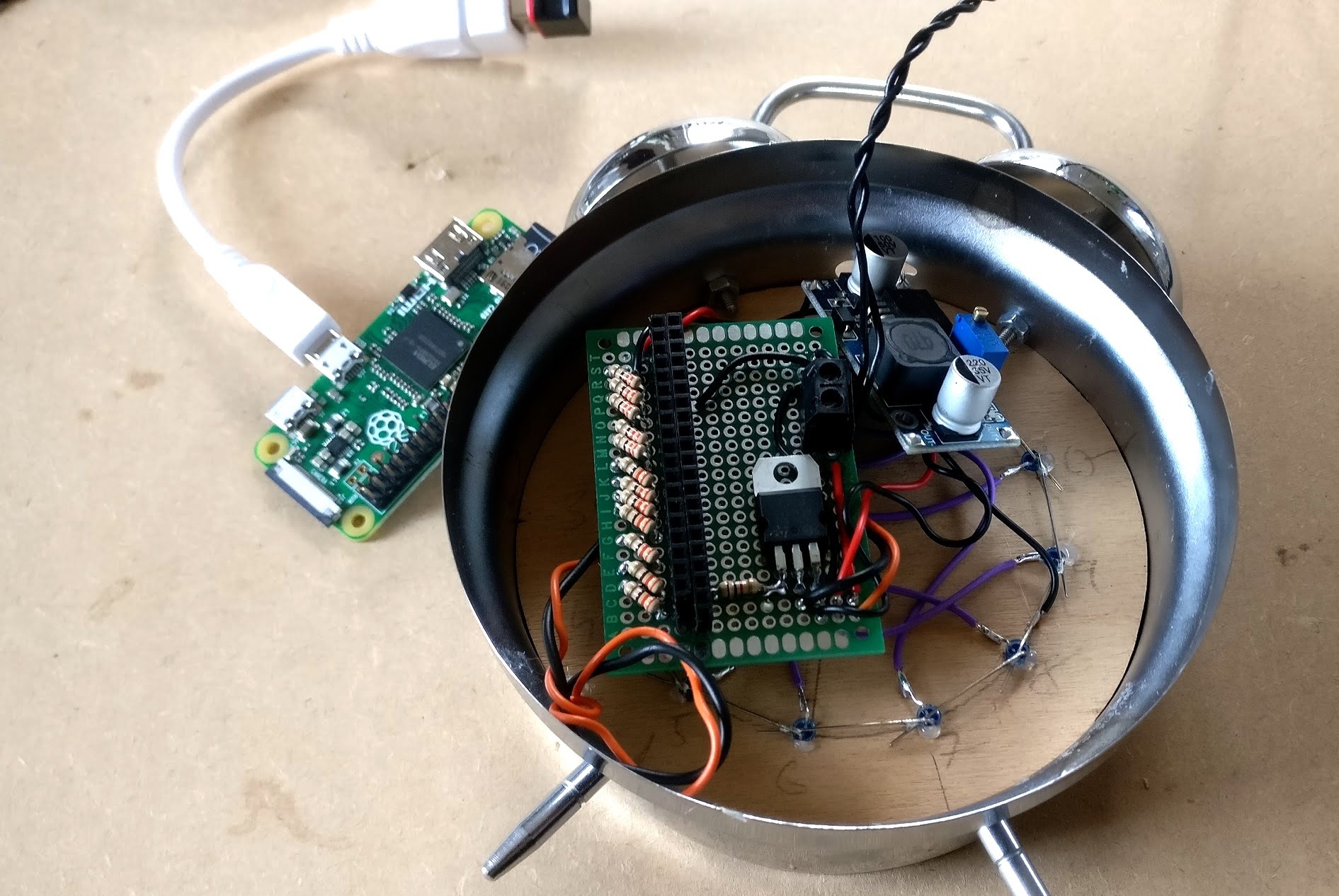
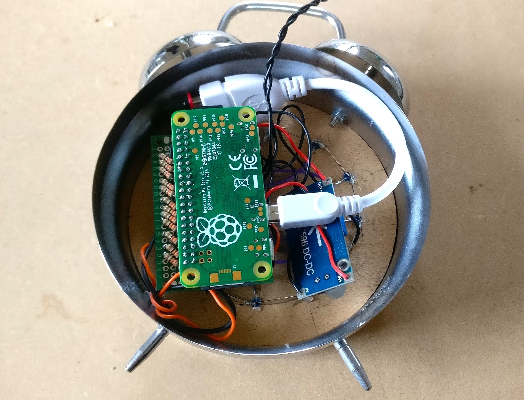
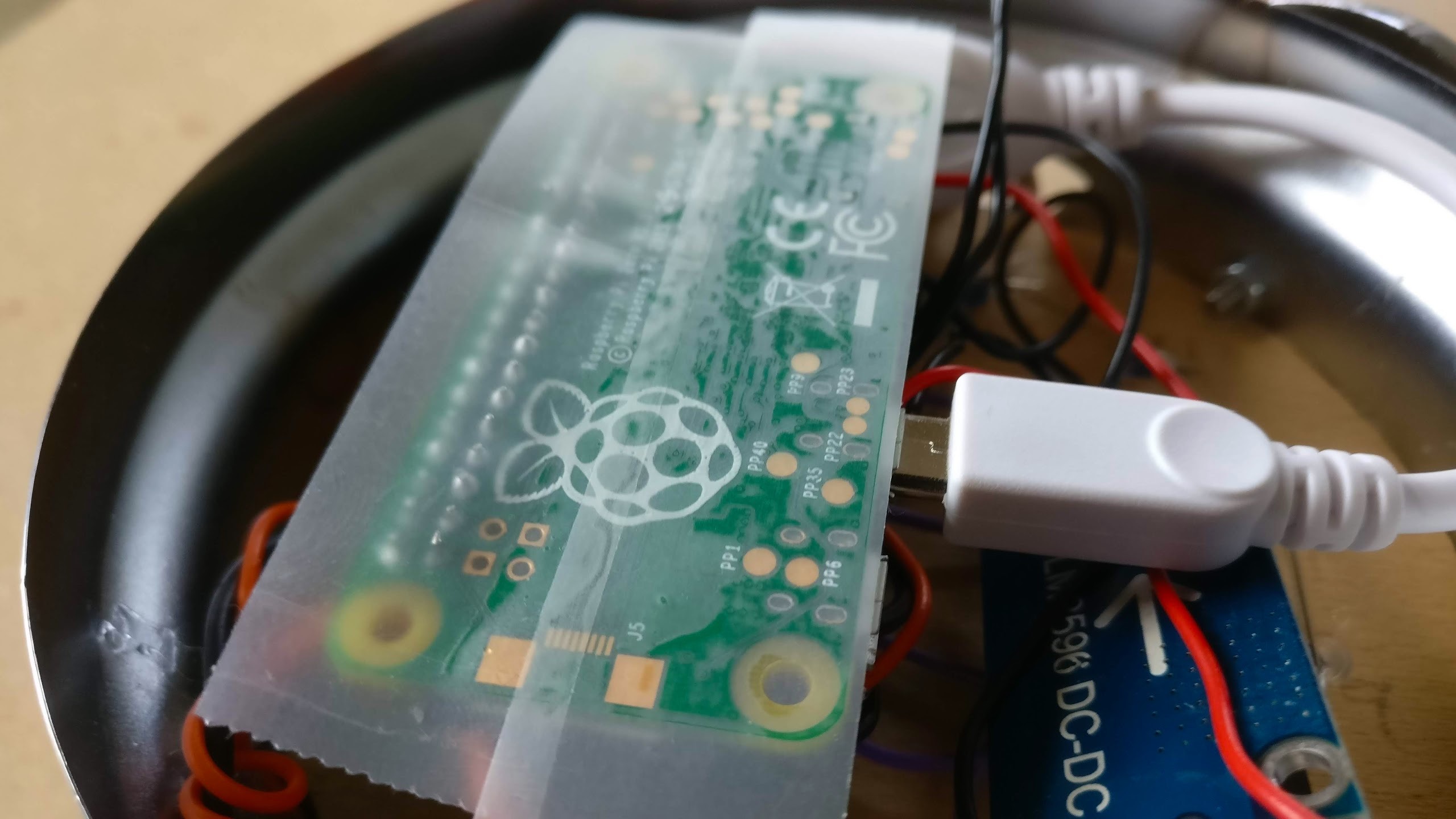
We've now covered all three elements of the circuit which are shown together in the overall circuit above. To save space and make the circuit neater put your circuit on strip board or prototype board. First solder the smallest components, the resistors, then the power transistor, any connectors and finally the wires. Plan out your circuit before you solder to make sure you have got space for everything.
I connected everything up on a prototyping PCB and used female header pins so the Pi could mount directly onto the PCB. The LEDs on the clock face are connected through resistors on one side of the board and I've kept space on the other side of the board for the power transistor and free for any other circuitry I might want to add later on.
Attach the clock face to the clock and make sure the electronics all fit in. Everything was quite a tight fit for me so you might need to do some rearranging. Connect up the power supply and run test1.py and test2.py from SSH to check everything works before attaching the back.
Upload the Code + Finish

The code
Finally if you haven't already, upload the code and adapt it as you like (using nano filename.py). The benefit of connecting to the Pi over SSH is that you can update the code without opening up the clock.
These python programs from Step 2 do the following:
- light_clock_simple.py simply displays the hour on the LEDs and fades up and down the LED strip at certain times
- light_clock_pwm.py is the same as above but also allows the brightness of the LEDs to be reduced and displays the minutes at a different brightness to the hours. You'll need to play around with the brightness levels of both so the contrast between the two is noticeable
These should provide a solid basis for adding to the code, for example you might want to add a button to snooze the light alarm.
To launch the program when the Pi boots we need to add '@reboot nohup python light_clock_pwm.py &'to the end of the crontab file which can be opened from the terminal with crontab -e. Restart your Raspberry Pi to check it's working with sudo shutdown -r now.
Potential additions
Here are some ideas of extra functionality that could be added
- Adding a snooze button
- Adding a lamp mode
- Connecting to IFTTT (eg light could turn on when you phone alarm goes off/flash when email received)
- Adding capacity touch capability ie make the clock into a touch lamp
You may notice when using PWM that at times, especially with lower brightness, the LED flickers a bit. This is because the Pi uses software PWM so CPU processes can affect the duty cycle. Having fewer processes running help with this so I used pared down operating system Raspbian Lite. Hardware PWM is also available on a few pins so if flicker is proving an issue, this might be something to look into.
I hope you have found this Instructable informative and either feel inspired to upcycle an old alarm clock or use elements of the code for your own project.