Lie Detector With the Data Sent to Your Phone
by tmcarbajal in Circuits > Microcontrollers
712 Views, 5 Favorites, 0 Comments
Lie Detector With the Data Sent to Your Phone
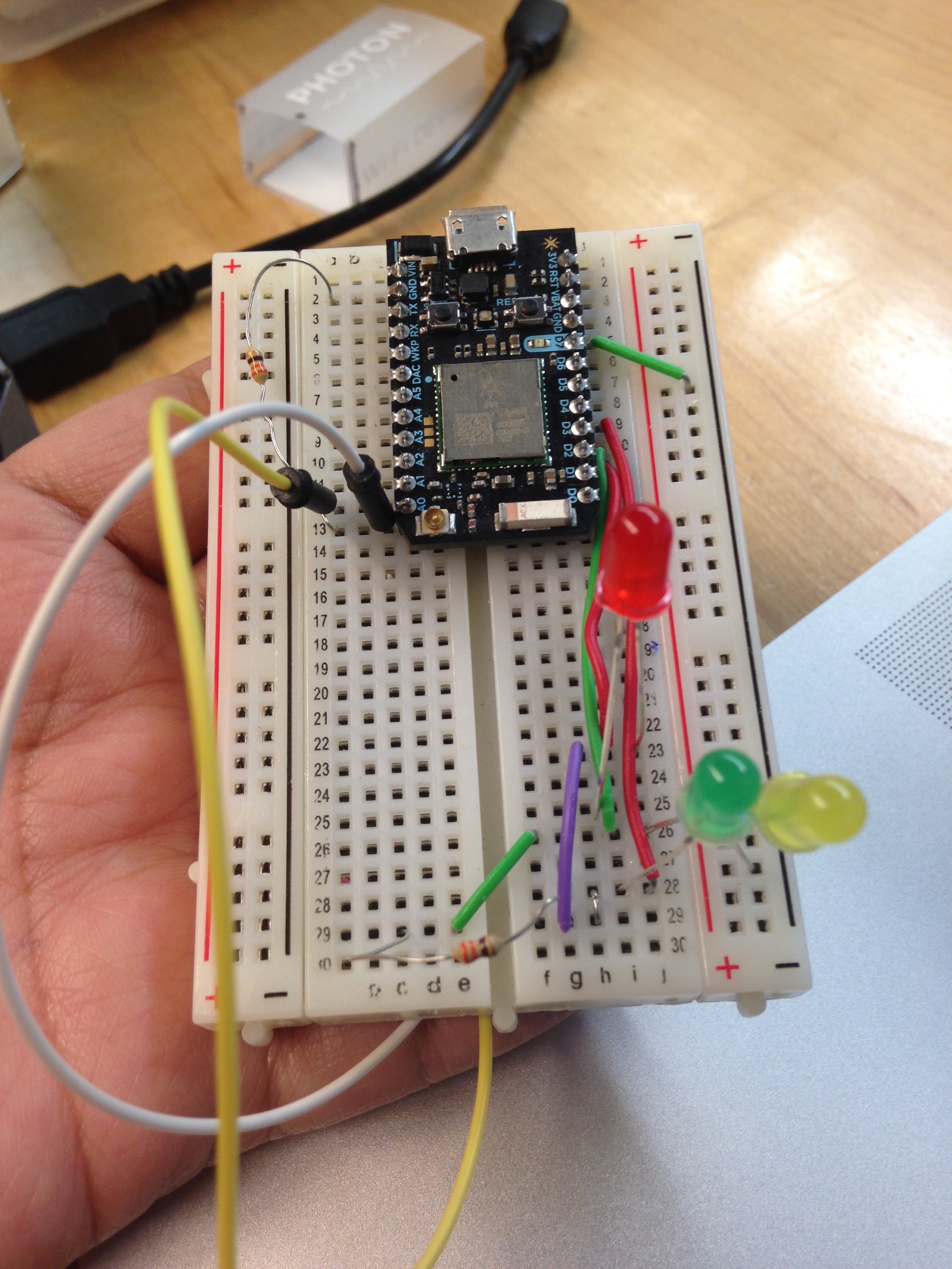
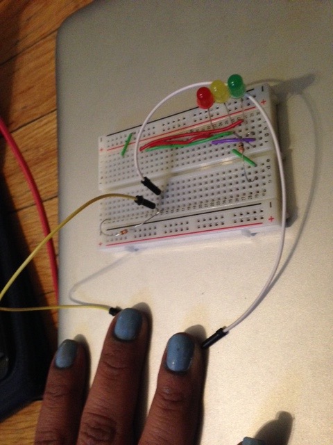
Skin changing conductivity based on our mood is called Electrodermal activity (EDA).
If you would like to learn more about this look at this link https://en.wikipedia.org/wiki/Electrodermal_activ... .
Once the lie detector has been constructed have the user put their middle and ring finger each on one of the visible jumper wire ends. You will have to view their typical data ranges by observing for a few minutes. Once you have done this ask a few basic questions (name, age, etc.) and then a question about something personal. It will give you a baseline of data to base your lie and truth decisions upon.
**An important thing to note is that the user of the lie detector has to truly be nervous about the topic at hand and not only about being connected to a lie detector.
Materials
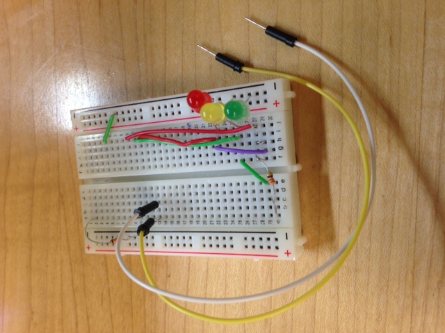
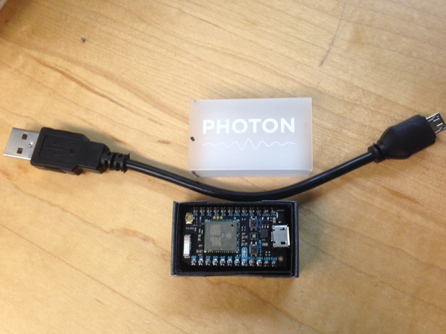
Materials-
Particle Photon
1 red LED
1 yellow LED
1 green LED 2
320 Volt Resistors
8 jumper wires
Breadboard
**You will also need to download two apps to an android phone and create an online account for the particle photonMaterials-
Download the Particle and Blynk Apps


After you've gathered your materials, download the Particle and Blynk app create an account and be sure to use the same email for both(it will make your life easier). Register the photon. The instructions to set up your particle photon are listed in this link. Your code can only be added on a computer, the link to send code to your photon through particle build is in this link. To download the blynk app the link is here. There will be a step in setting up the code that will connect the two programs.
Wiring
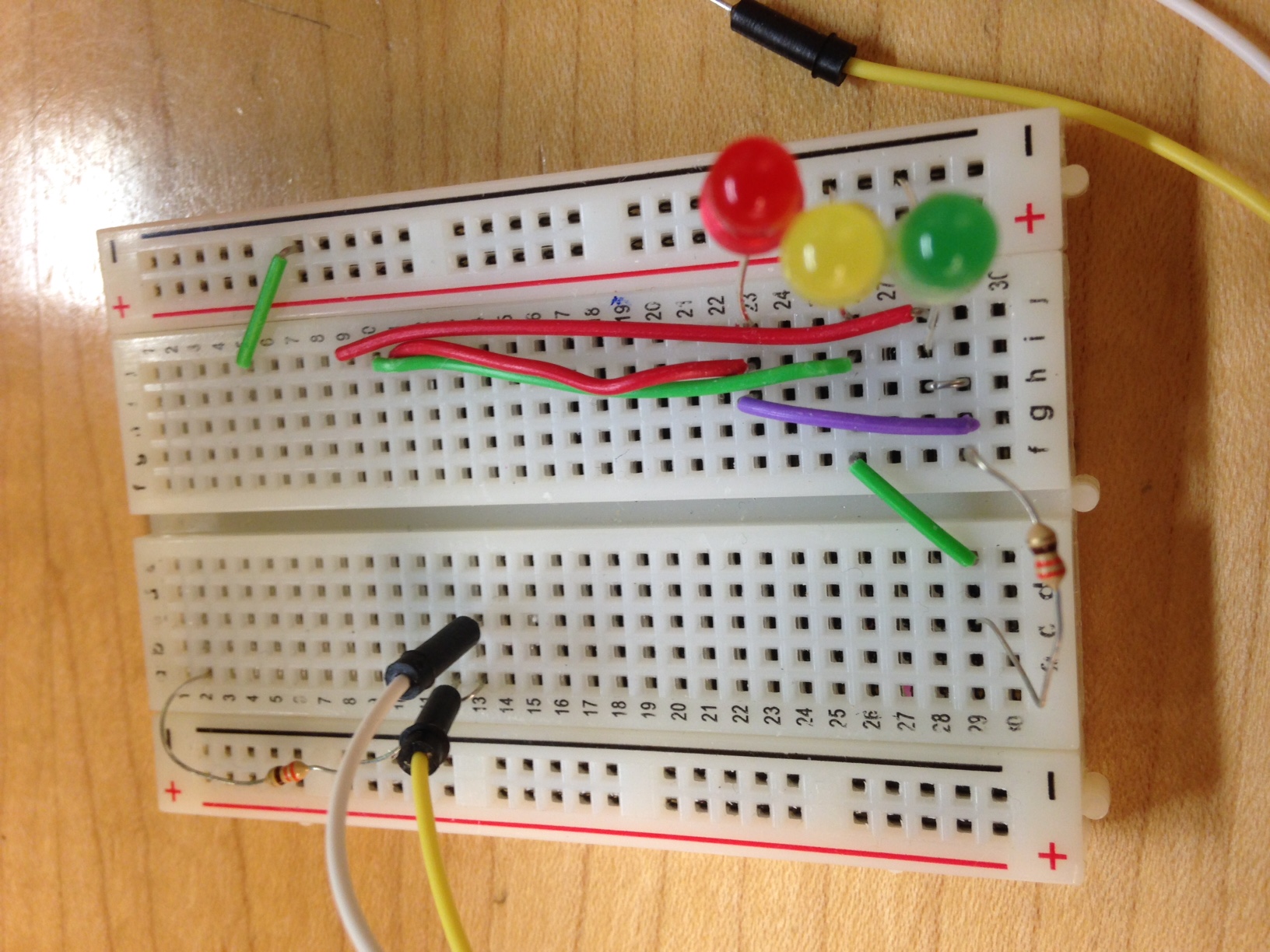
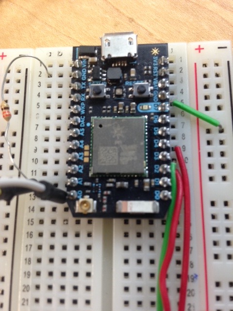
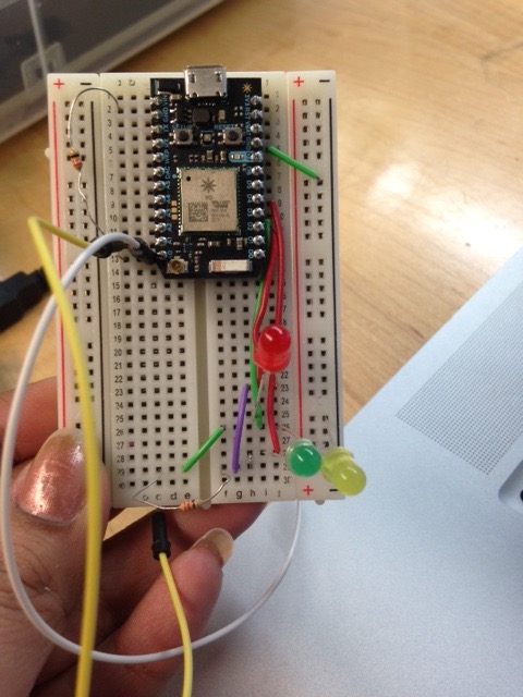
Resistor 1->Ground to A0
Red LED(Place midway on the board)-> Positive(Long leg) to last column Negative(Short leg) to negative
Yellow LED(Place 3 squares down from Red)-> Positive(Long leg) to last column Negative(Short leg) to negative
Green LED(Place 3 squares down from Yellow)- Positive(Long leg) to last column Negative(Short leg) to negative
Jumper wire 1->A0 to nothing Jumper wire 2 ->A1 to nothing Jumper wire 3->Ground to negative Jumper wire 4->A0 toA1 Jumper wire 5->D1 to square next to positive green leg Jumper wire 6->D2 to square next to positive yellow leg Jumper wire 7->D3 to square next to positive red leg Jumper wire 8->Next to positive green leg to resistor 2 Jumper wire 9 ->Next to positive yellow leg to resistor 2 Jumper wire 10->Next to positive red leg to resistor 2 Resistor 2->In the same column as A0 to row below green LED
Blynk App- Value Display Widget
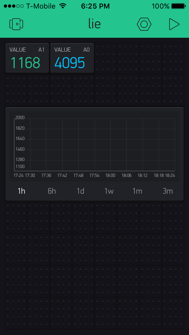
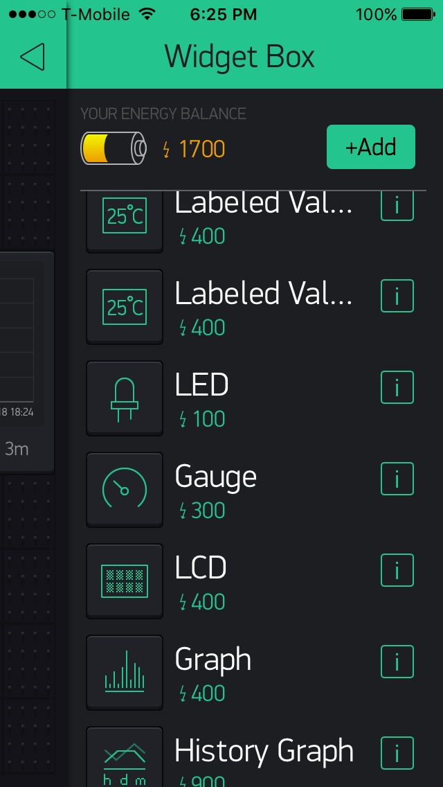

After setting up the Blynk app with your photon tapping the screen and add the graph and two of the value display widgets.
Once you have added them click on one of the value display widgets and connect it to A0, connect the second one to A1.
Lights- Particle Code
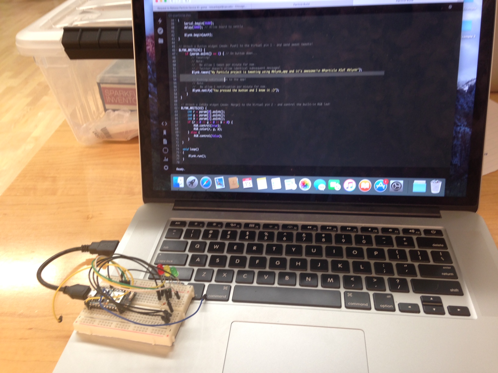
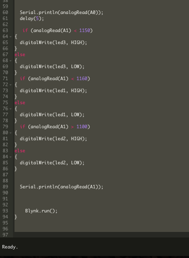
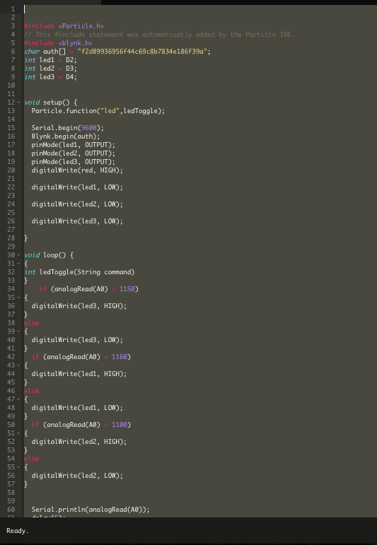
Currently the LED's connected to the photon turn on under the correct values but to get the correct value to turn on and demonstrate if a lie or truth is being told you will have to increase or decrease them while looking at the data.
The code is given below, copy and paste it https://build.particle.io. After you have done this click on the downward facing flag that is libraries and download the BLYNK library. Add it to the lie detector project you are working on.
#include // This #include statement was automatically added by the Particle IDE.
#include char auth[] = "f2d89936956f44c69c8b7834e186f39a";
int led1 = D2; int led2 = D3;
int led3 = D4;
void setup() { Particle.function("led",ledToggle);
Serial.begin(9600); Blynk.begin(auth);
pinMode(led1, OUTPUT);
pinMode(led2, OUTPUT);
pinMode(led3, OUTPUT);
digitalWrite(red, HIGH);
digitalWrite(led1, LOW);
digitalWrite(led2, LOW);
digitalWrite(led3, LOW); }
void loop()
{
{ int ledToggle(String command) }
if (analogRead(A0) < 1150)
{ digitalWrite(led3, HIGH); }
else { digitalWrite(led3, LOW); }
if (analogRead(A0) < 1160)
{ digitalWrite(led1, HIGH); }
else { digitalWrite(led1, LOW); }
if (analogRead(A0) > 1100) { digitalWrite(led2, HIGH); }
else { digitalWrite(led2, LOW); }
Serial.println(analogRead(A0));
delay(5); if (analogRead(A1) < 1150)
{ digitalWrite(led3, HIGH); }
else { digitalWrite(led3, LOW); }
if (analogRead(A1) < 1160) { digitalWrite(led1, HIGH); }
else { digitalWrite(led1, LOW); }
if (analogRead(A1) > 1100)
{ digitalWrite(led2, HIGH); }
else { digitalWrite(led2, LOW); }
Serial.println(analogRead(A1));
Blynk.run(); }
Finished Product
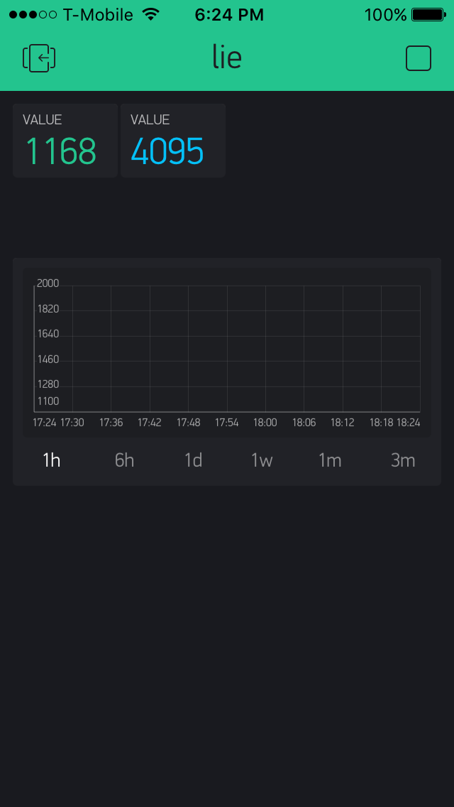

The finished product will send the data to your phone, you will have to analyze it to see if the person is lying or not and the LED's will all turn on but will not adjust according to truth, normal, or lie according to the lights if you don't change the values according to your constants. Overall one of the most difficult aspects of the project was adding the code to connect the data transmittance to the phone but as long as you attach all of the code it will work.