Li-ion Cell Charger With TP4056 and XIAO ESP32S3
by Arnov Sharma in Circuits > Electronics
2927 Views, 5 Favorites, 0 Comments
Li-ion Cell Charger With TP4056 and XIAO ESP32S3


Hello everyone, and welcome back.
Here's something useful: a Li-ion Cell Charger Setup.
This Li-ion cell charger features an incorporated XIAO ESP32S3-based battery voltage monitoring system that shows the battery's current voltage as measured by a simple voltage divider circuit.
We are using the well-known TP4056 Li-ion Charging IC to charge the Li-ion cell. We are utilizing a DC-DC Buck Module to supply a stable 5V to this circuit. It does this by converting the 12V input side to 5V 3A or QC3.0, which is plenty to power the Li-ion cell. Moreover, it contains a few USB ports that can be used to power XYZ devices.
Essentially, there are two primary applications for this device: first, it charges Li-ion cells, which is very helpful because I have a lot of fresh Li-ion cells that are stored for a long time.
Since their internal resistance decreases after more than four to five months, we can simply put any low-voltage cell in and charge it to its operating voltage. Second, it offers steady 5V via USB ports, which is sufficient to power XYZ USB devices.
This whole Instructables is about the building process, so let's get started.
Supplies
Here are the materials used in this build:
- Custom PCB
- XIAO ESP32S3 Sense
- DC-DC Buck Module
- 3D-printed parts
- SSD1306 OLED
- TP4056
- 1K resistor
- Blue and Green 0805 LED
- 1uF Capacitor
- M2 Screws
DESIGN


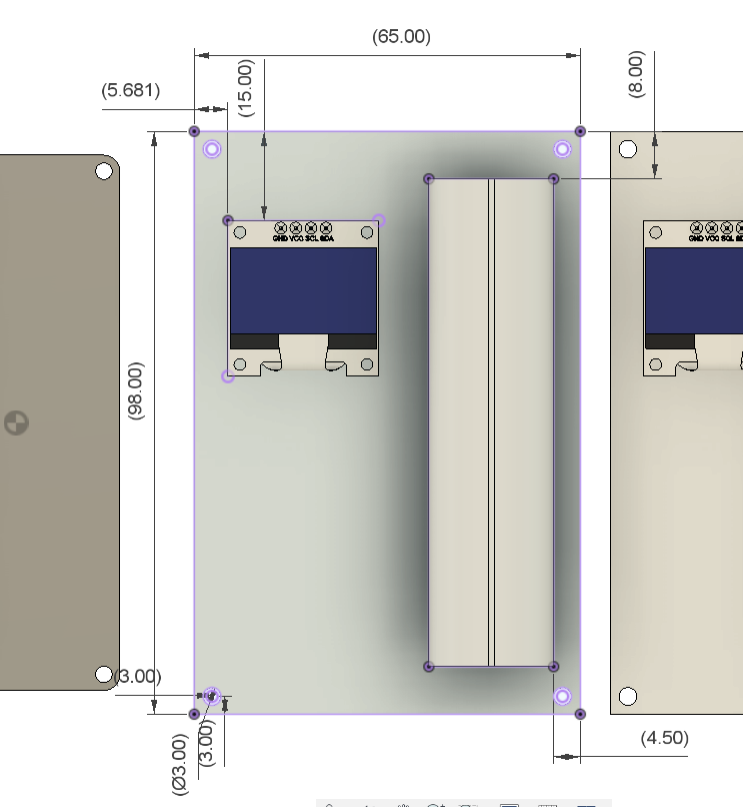
The process of designing the battery charger began with the making of a model for the circuit, which will include an SSD1306 screen and a Li-ion cell holder mounted on a 1.5 mm thick PCB.
In addition, we had to model the circuit for the DC-DC Buck Module, which is mounted on the bottom side, and the main circuit on the top side.
The concept was to use a 3D printed frame made out of a base attached to four mounting pillars, one of which had a holder for a rocker switch, to connect these two circuits together.
Following the model's preparation, we used yellow PLA and a 0.4mm nozzle with 20% infill to 3D print each part of the frame.
Downloads
CIRCUIT


Let's have a closer look at the circuit.
It consists mainly of three sections: the XIAO ESP32S3 and SSD1306 display are connected via the XIAO MCU's I2C pins in the first section.
The voltage divider part comes next, and it is made up of two resistors that are wired in series between the battery + port and GND. The D0 pin of the XIAO, which will be reading analog readings and showing analog values on a serial monitor, is linked to the middle connection of the voltage divide. These analog values will subsequently be converted into voltage values.
The TP4056 setup is the third and most crucial element of this project. It is a commonly used Li-ion charging IC that is used when we only need to charge Li-ion or Li-Po batteries. Because of its overcharge and overdicharge protection features, the battery voltage is maintained between 2.5 and 4.2 V, which is the optimal range for lithium-ion batteries to operate in.
We have added a CON2 port and paired it with a switch in series to charge the cell. The 5V/3A input of a DC-DC Buck converter will be connected to the entire circuit. Li-ion cells will be charging with a maximum current of 1A due to TP4056, and this maximum current will decrease linearly with increasing battery voltage.
After the schematic is complete, we use the board dimensions from the previously created circuit CAD file to create the project's PCB using PCB Cad software.
Seeed Fusion Service


After finalizing the PCB and generating its Gerber data, I sent it to SEEED Studio for samples.
The PCB was ordered in a black solder mask with white silkscreen.
PCBs were received in a week, and their quality was super good considering the rate, which was also pretty low.
Seeed Fusion PCB Service offers one-stop prototyping for PCB manufacture and PCB assembly, and as a result, they produce superior-quality PCBs and fast turnkey PCBAs within 7 working days.
Seeed Studio Fusion PCB Assembly Service takes care of the entire fabrication process, from Seeed Studio Fusion Agile manufacturing and hardware customization to parts sourcing, assembly, and testing services, so you can be sure that they are getting a quality product.
After gauging market interest and verifying a working prototype, Seeed Propagate Service can help you bring the product to market with professional guidance and a strong network of connections.
Next is the PCB assembly process.
PCB ASSEMBLY PROCESS


- Using a solder paste dispensing needle, we first add solder paste to each component pad individually to begin the PCB assembly process. In this instance, we are using standard 37/63 solder paste.
- Next, we pick and place all the SMD components in their places on the PCB using an ESD tweezer.
- With extreme caution, we lifted the complete circuit board and placed it on the SMT hotplate, which increases the PCB's temperature to the point at which the solder paste melts and all of the components are connected to their pads.
- Next, we add all the THT components, which include the header pins, CON2 screw terminal, CON2 JST connector, and SSD1306 display, to their locations and then solder their pads using a soldering iron.
- At last, we added the Li-ion 18650 Battery Holder in its position using a soldering iron.
The circuit is now complete.
RESULT SO FAR


Here is the finished PCB assembly end result: a Li-ion cell charging circuit based on the TP4056 with an SSD1306 display and header pins for an XIAO MCU and Li-ion cell holder.
The assembly is now prepared for the first test after we installed the XIAO ESP32S3 on its header pins.
CODE
Here's the code that was used in this build, and its a simple one: it measures analog voltage using a voltage divider circuit and displays the corresponding voltage value on a 128x64 OLED screen using the Adafruit SSD1306 library.
#include <Wire.h>
#include <Adafruit_SSD1306.h>
#include <Adafruit_GFX.h>

#define OLED_WIDTH 128
#define OLED_HEIGHT 64

#define OLED_ADDR   0x3C

Adafruit_SSD1306 display(OLED_WIDTH, OLED_HEIGHT);

float input_volt = 0.0;
float temp=0.0;
float r1=100000.0;    //r1 value
float r2=10000.0;      //r2 value


void setup() {
  display.begin(SSD1306_SWITCHCAPVCC, OLED_ADDR);
  display.clearDisplay();
  Serial.begin(9600);
}

void loop() {
  int analogvalue = analogRead(D0);
    temp = (analogvalue * 0.8) / 1024.0;  // FORMULA USED TO CONVERT THE VOLTAGE
    input_volt = temp / (r2/(r1+r2));
    if (input_volt < 0.1)
    {
      input_volt=0.0;
    }


  display.setTextSize(2);
  display.setTextColor(WHITE);
  display.setCursor(0, 0);
  display.println("Voltage=");
 // display.display();
  display.setTextSize(2);
  display.setTextColor(WHITE);
  display.setCursor(0, 20);
  display.println(input_volt);
  display.display();

  display.clearDisplay();


 delay(300);

}
Here's the main part of this sketch
void loop() {
  int analogvalue = analogRead(A0);
  temp = (analogvalue * 0.8) / 1024.0;  // Formula used to convert the voltage
  input_volt = temp / (r2 / (r1 + r2));

  if (input_volt < 0.1) {
    input_volt = 0.0;
  }

  // Display voltage on OLED
  display.setTextSize(2);
  display.setTextColor(WHITE);
  display.setCursor(0, 0);
  display.println("Voltage=");
  display.setTextSize(2);
  display.setTextColor(WHITE);
  display.setCursor(0, 20);
  display.println(input_volt);
  display.display();

  display.clearDisplay();

  delay(300);
}
Here, the MCU Reads the analog voltage from pin A0, converts it to a voltage value, and displays it on the OLED screen. The loop repeats with a delay of 300 milliseconds between readings. The displayed voltage is calculated using a voltage divider formula based on the resistor values r1 and r2. If the calculated voltage is less than 0.1, it is set to 0.0 to avoid displaying small, insignificant values.
TESTING


First, we inserted the Li-ion cell into the battery socket with the proper polarity. It is important to avoid placing the cell in the holder incorrectly, as this could cause the TP4056 to short circuit.
Next, we compare the voltage of the cell with the voltage measured by the multimeter.
DC-DC Buck Module and Charger Circuit Assembly


- Using a soldering iron, we attach positive and negative wires to the DC buck module's GND and 5V terminals before beginning the main process.
- The positive and negative were then added to the charging circuit via input using a screw terminal connector.
The system is powered on, the OLED turns on, and the current voltage of the Li-ion cell is displayed after 12V is connected through the barrel DC Jack of the DC DC Module.
- Using four M2 screws, we now attach the DC-DC Module to the 3D-printed base.
- Next, we use four M2 screws to secure the base to the four circuit holding pillars.
- Furthermore, we connected the rocker switch's JST connector to the circuit and installed a rocker switch on one of the circuit holding pillars.
- Finally, we position the charging circuit on the top side and fasten it there using M2 screws.
The assembly is now complete.
FINAL RESULT


The end product of this project is a lithium-ion charger with an integrated battery monitoring system. The voltage of the battery is detected by the XIAO MCU and shown on the OLED screen.
The TP4056 features two indicator LEDs. One LED illuminates during the charging process, and it switches off the full charge LED when the battery reaches 4.2V. In our instance, a blue LED serves as the full charge indicator, and a green LED serves as the charging indicator.
Furthermore, this configuration has four USB ports, each of which can deliver a steady 5V and a maximum of 3A, which is sufficient to power XYZ devices like an Arduino project or a Raspberry Pi.
Leave a comment if you need any help regarding this project. This is it for today, folks.
Thanks to Seeed Studio Fusion for supporting this project.
You guys can check them out if you need great PCB and stencil service for less cost and great quality.
And I'll be back with a new project pretty soon!