Lets Build a LED CUBE
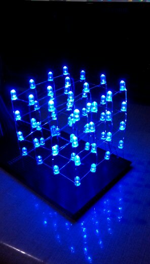
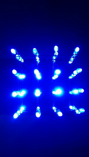
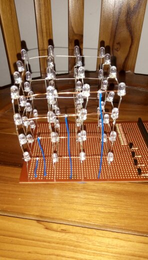
Hello everyone! . In this instructable I'm going to show you how I built my 4X4X4 Led Cube.
For this cube I used Blue LEDS and NPN Transistors to drive ground signals to the layers of the cube to
make coding easier. I hope you are all going to like this instructable.
Oder Your Parts.
The parts list
- 64 X Leds
- 16 X 220 Ohm resistors
- 4 x 1K resistors
- 4 X 2n2222A Transistors
- Prototyping PCB
- Arduino UNO
- Jumper wire
The tools needed for this build
- A drill machine
- 5mm drill bit
- pliers
- soldering iron
- solder
additional parts needed
- A piece of 10mm thick or more piece of wood.
Build the JIG
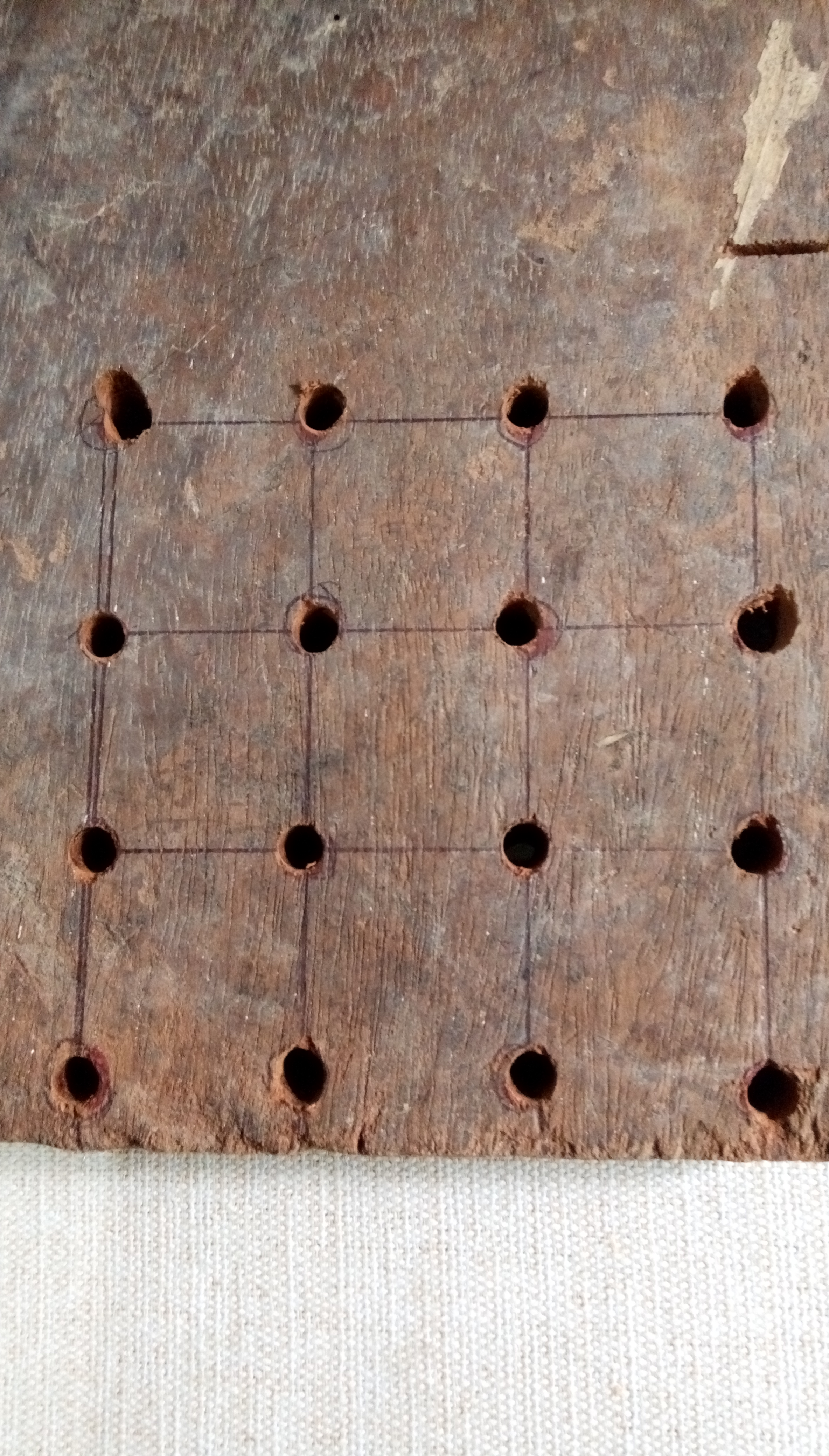
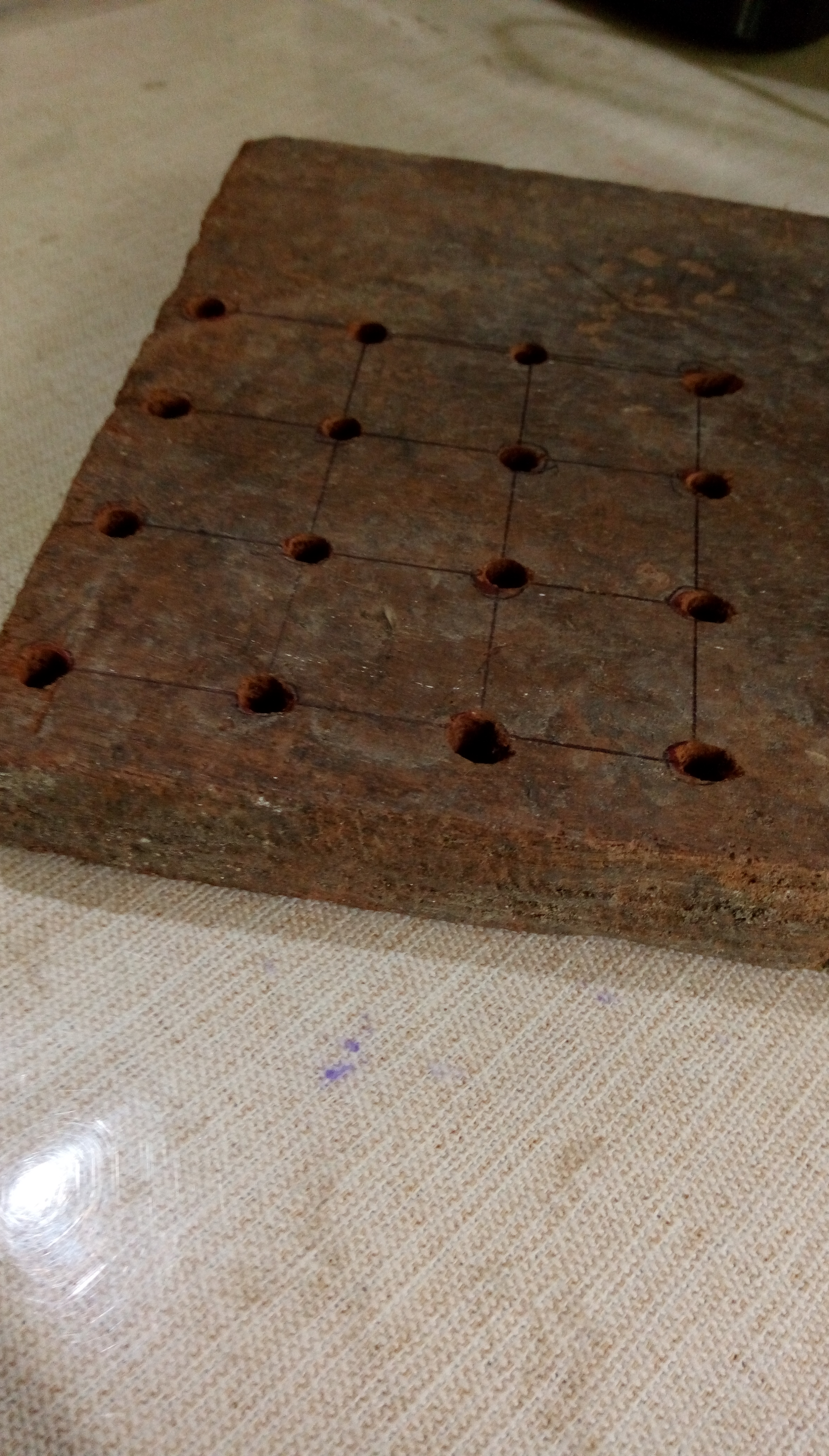
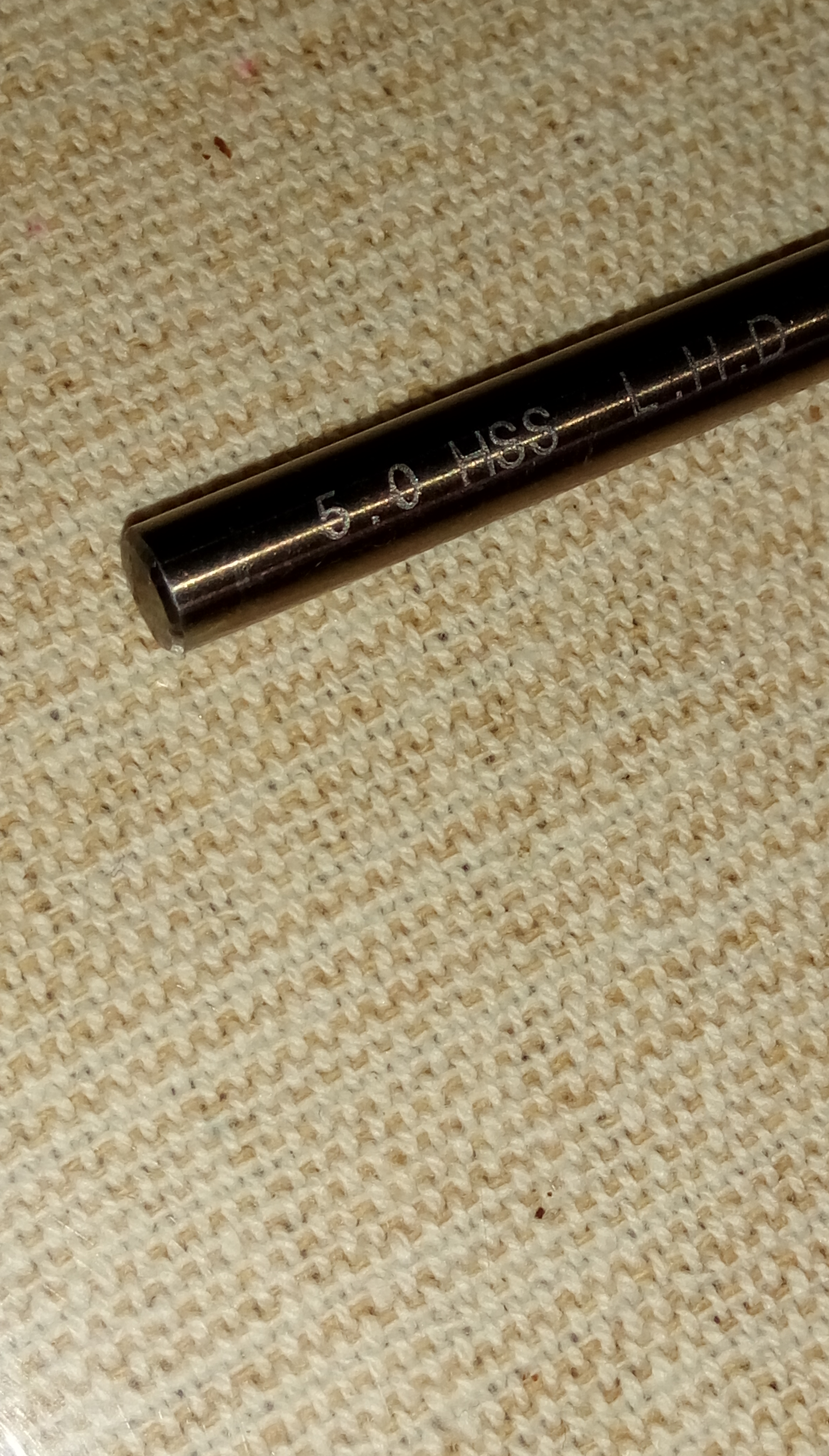
We will be building the jig to hold the LEDS while soldering, from the piece of wood.
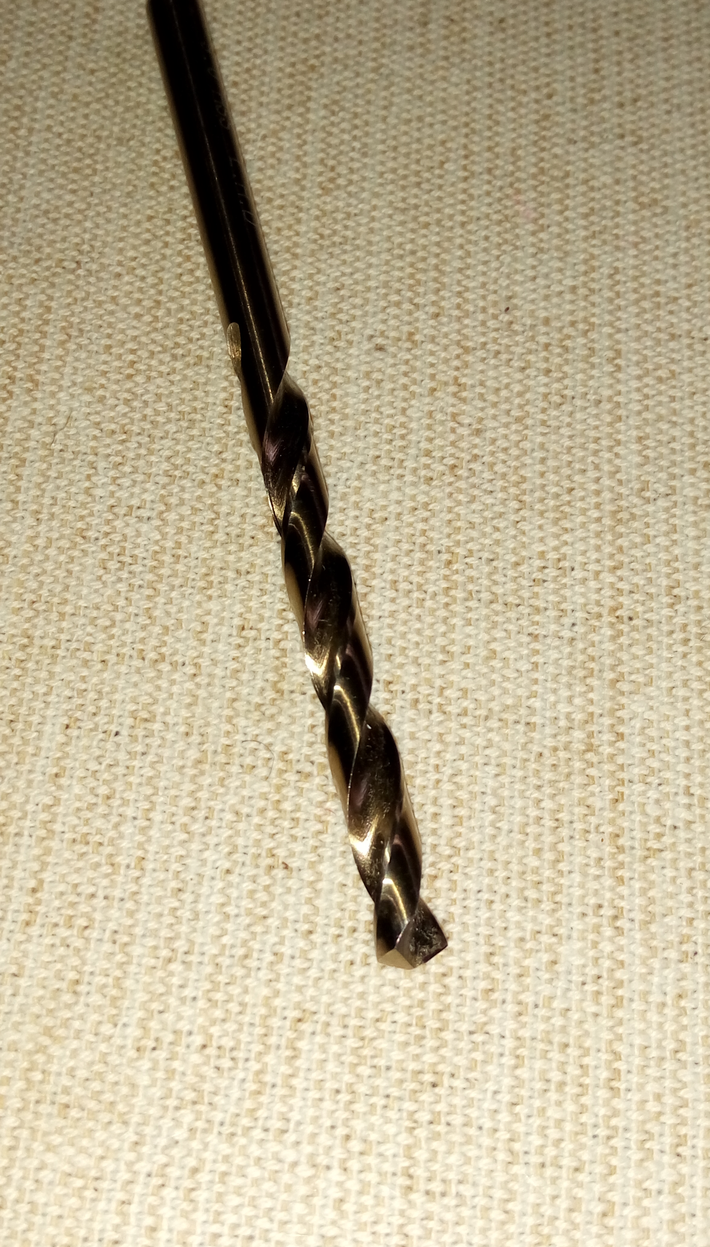
First install the 5mm drill bit to drilling machine and power it on. Mark the jig on to the wood, placing each hole approximately 2.5cm apart. Then take your drilling machine and drill away!.
The end result should look like these pictures given.
Solder the LEDS
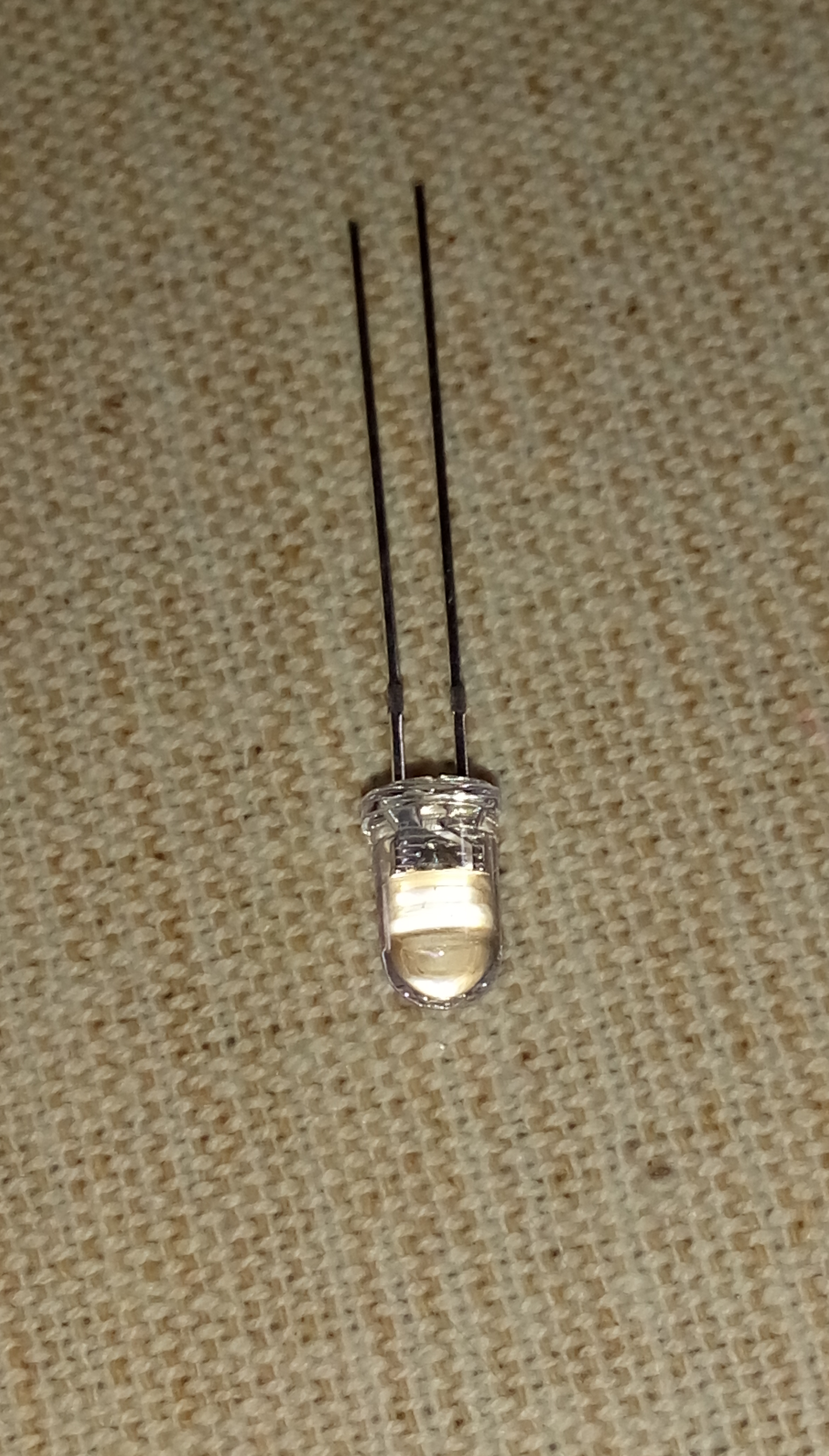
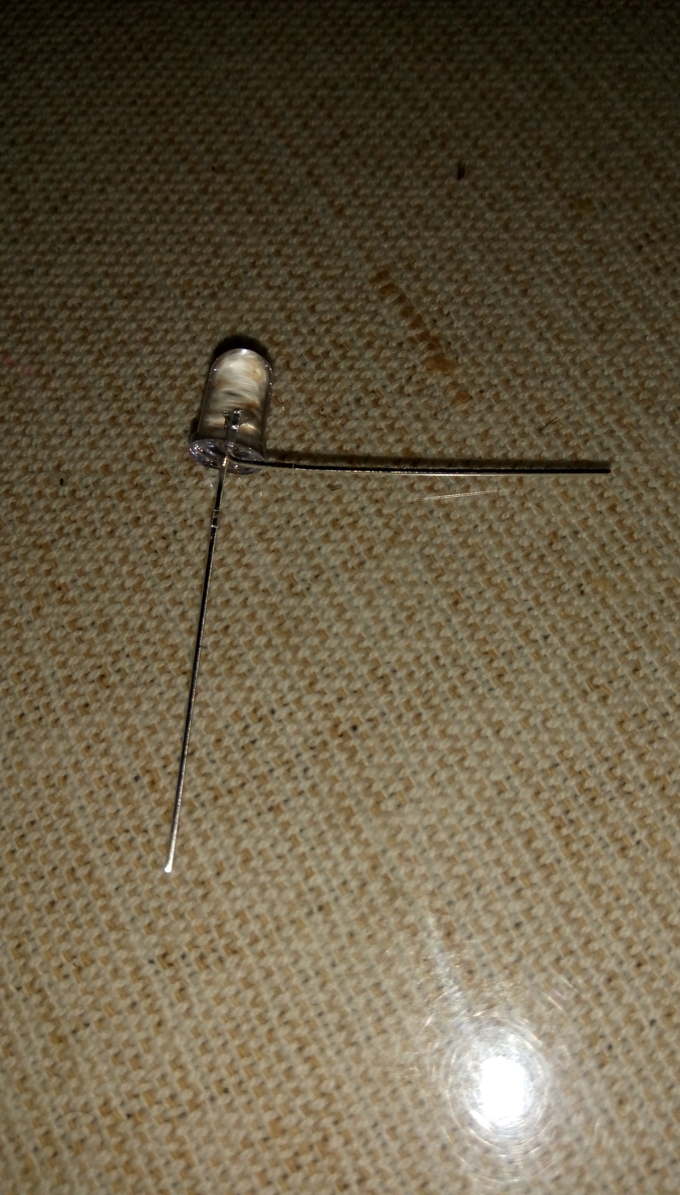
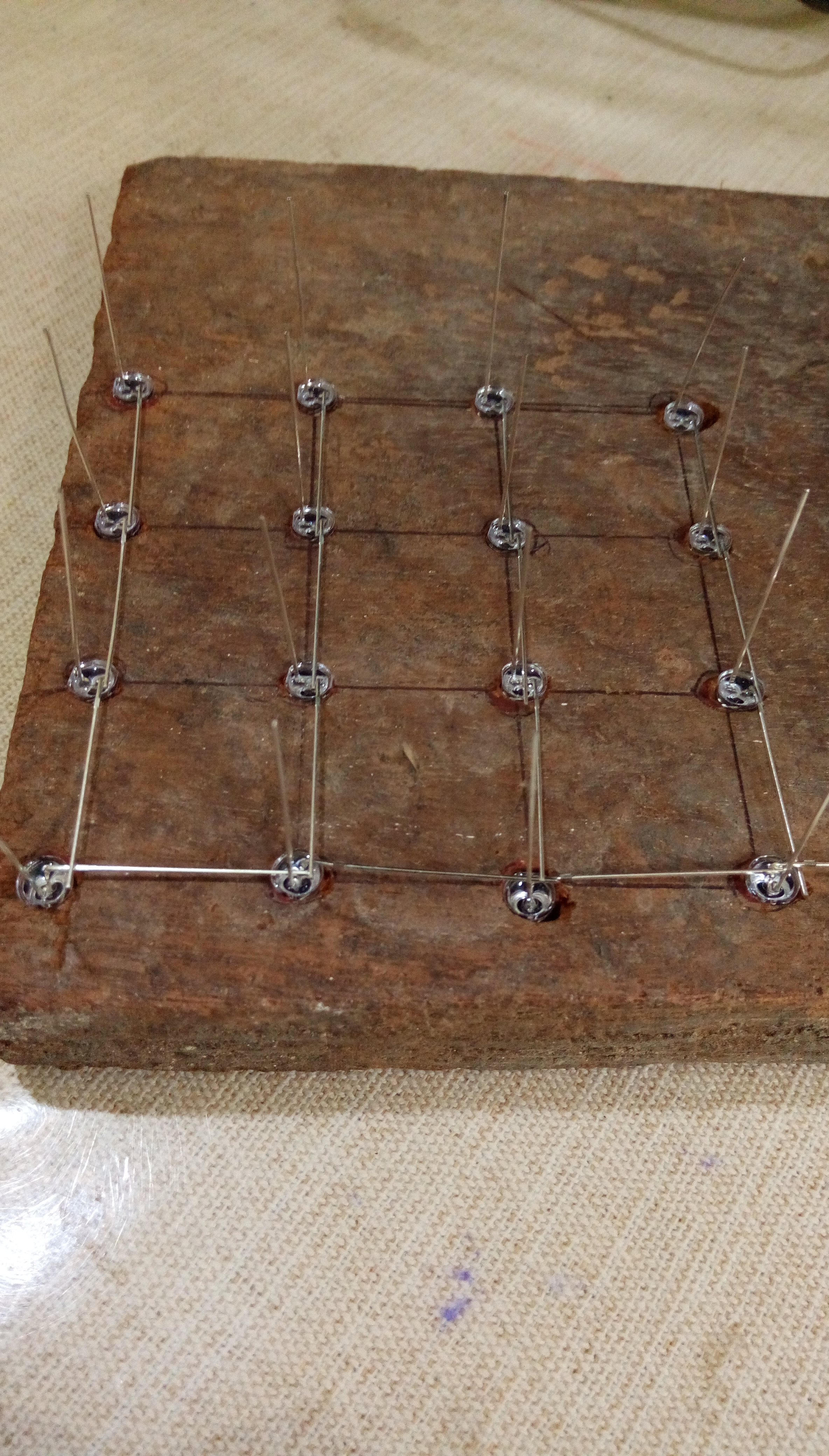
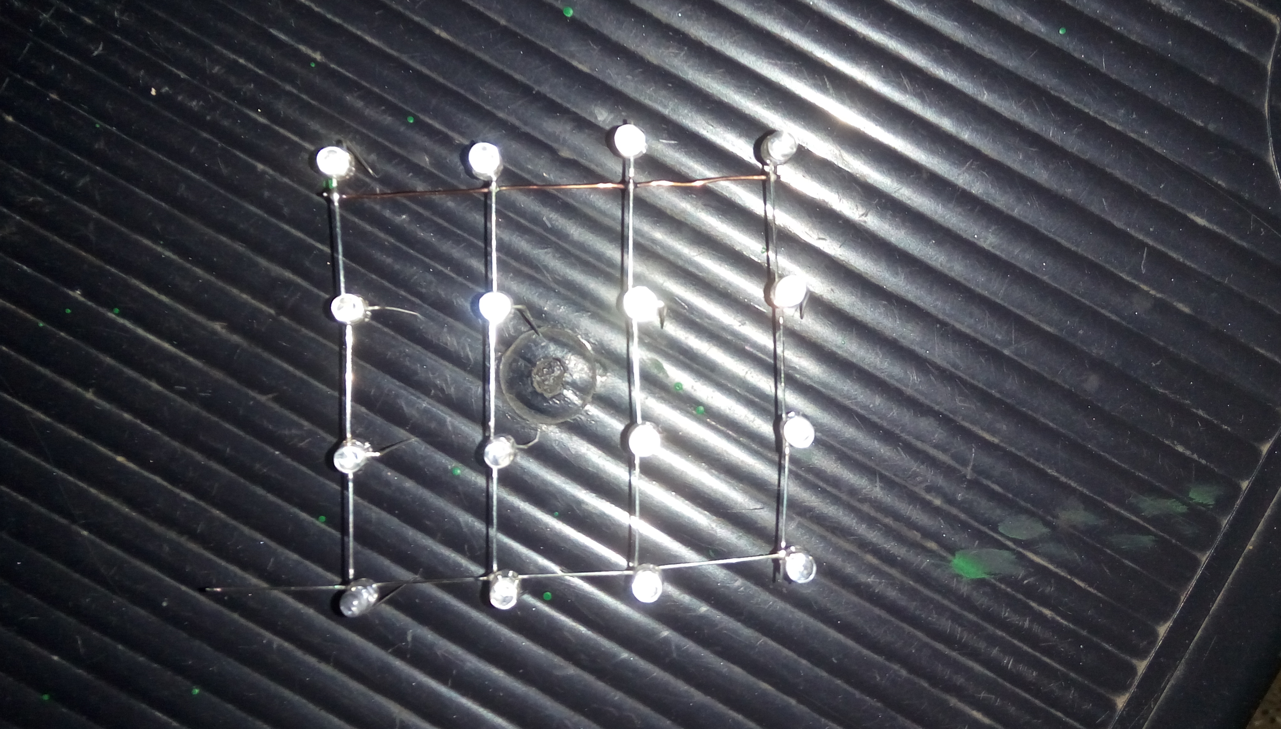
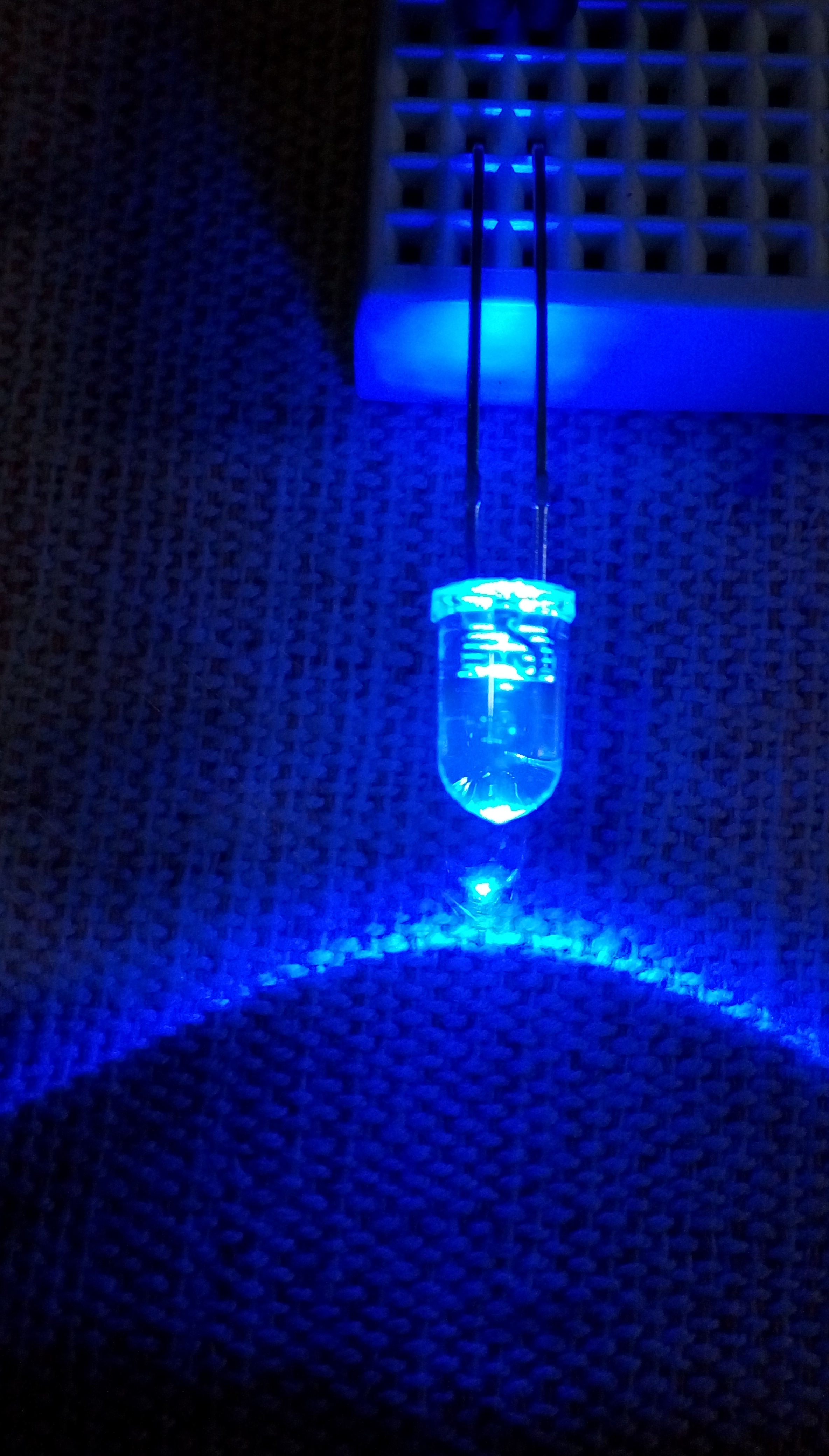
First test each LEDS to see if they work, unless after you have soldered them and found out there is a damaged or broken LED it will be hard to desolder it, especially if one of them happens to be soldered inside the cube.
Take a LED and bend it as it is shown in the pictures. Insert the them to the holes in the jig and solder all the cathodes as shown in the pictures.
But make sure you don't apply too much heat to the LEDS or they might get damaged.
I've also added a copper wire to one side of the layer to reinforce it, so that it won't bend easily.
Solder the Cube
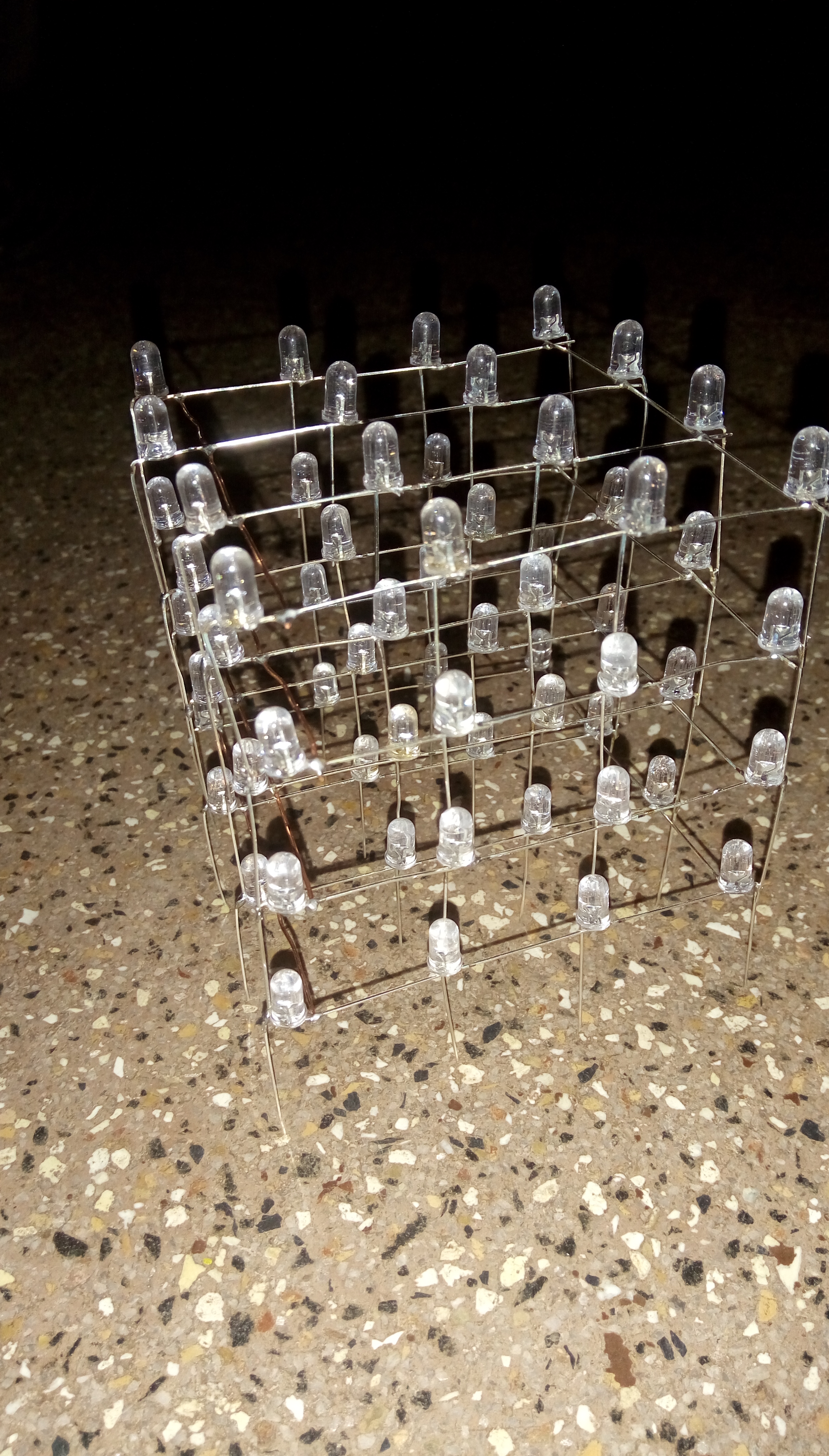
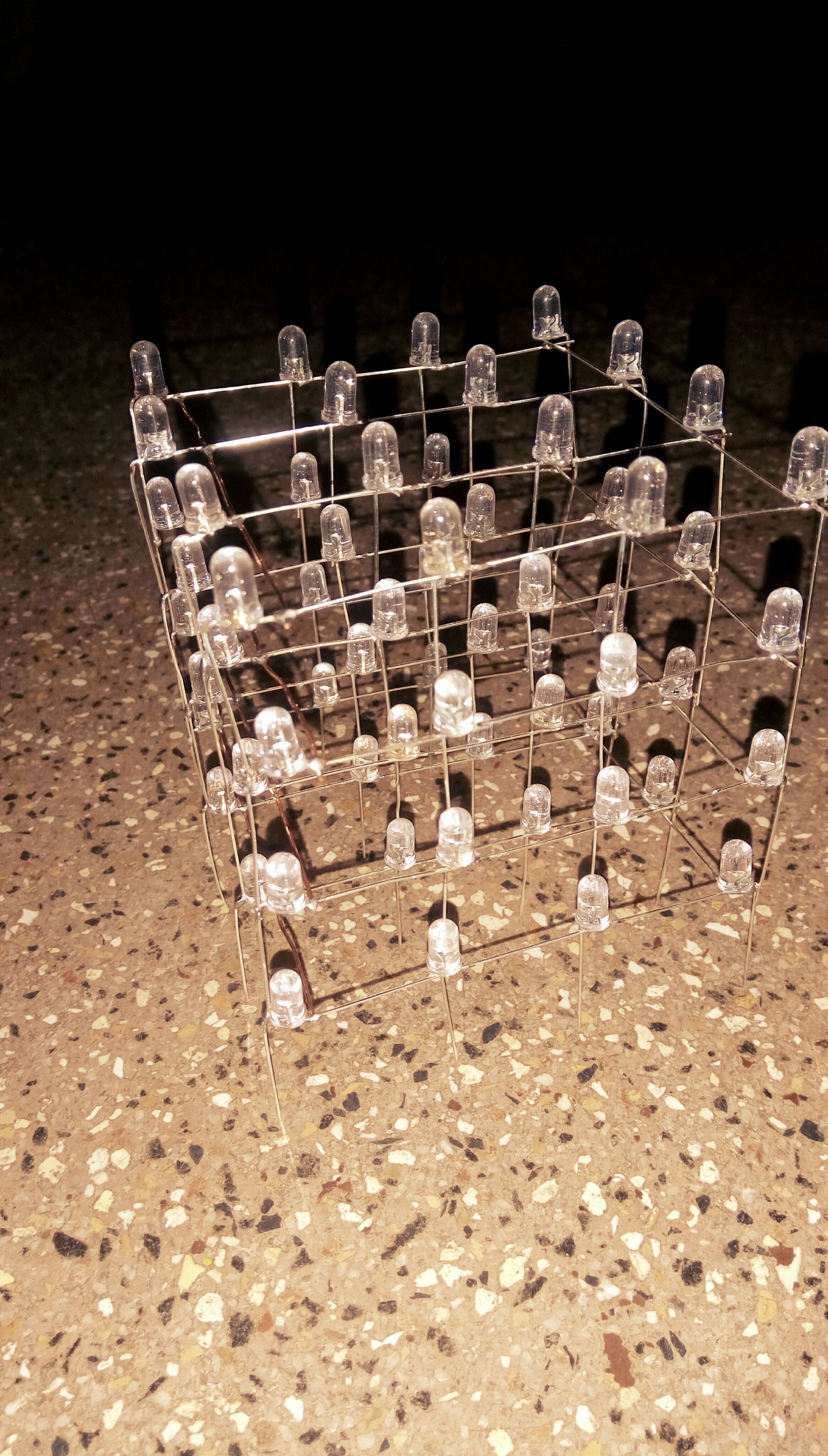
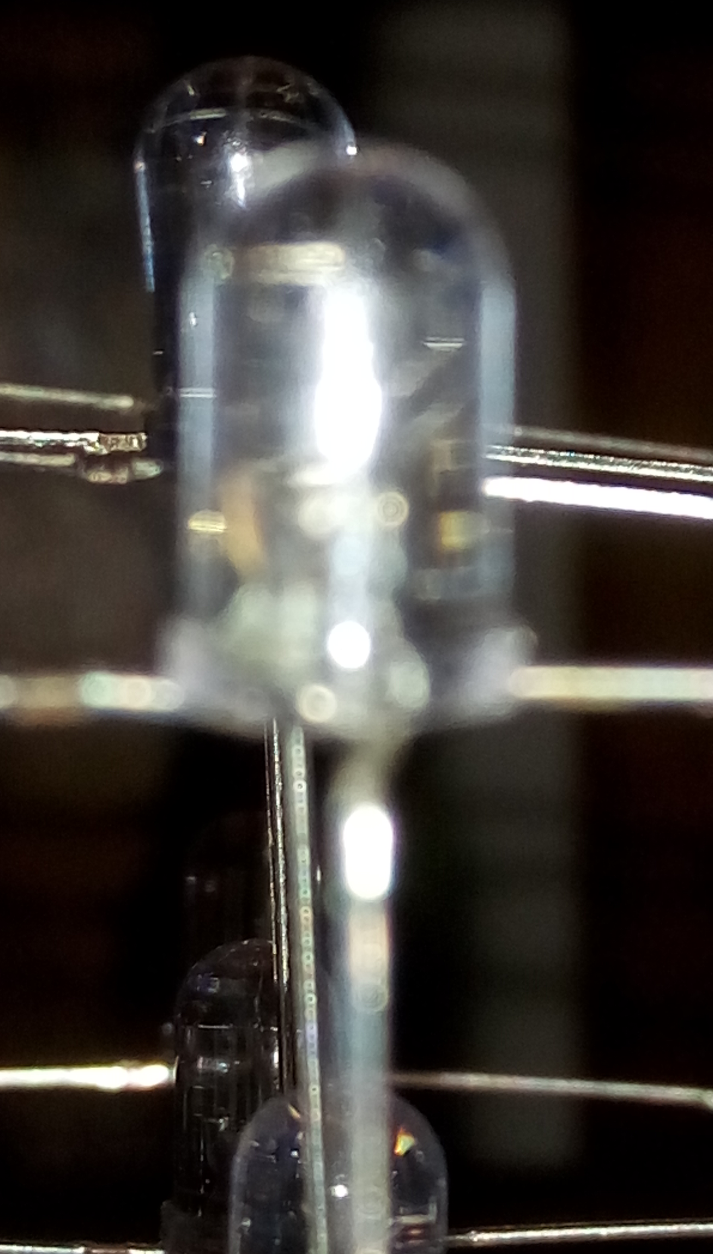
Once you are finished with soldering the four layers, it is time solder them on top of each other by the anodes to form the cube.
The end result would be a LED CUBE with anode leads coming out from the bottom of it.
These anodes will later be soldered to a PCB.
Solder the Cube and Cathodes Circuit to the PCB
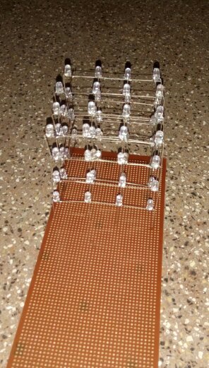
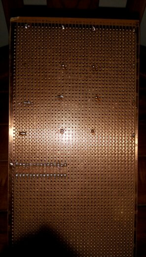
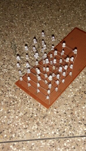
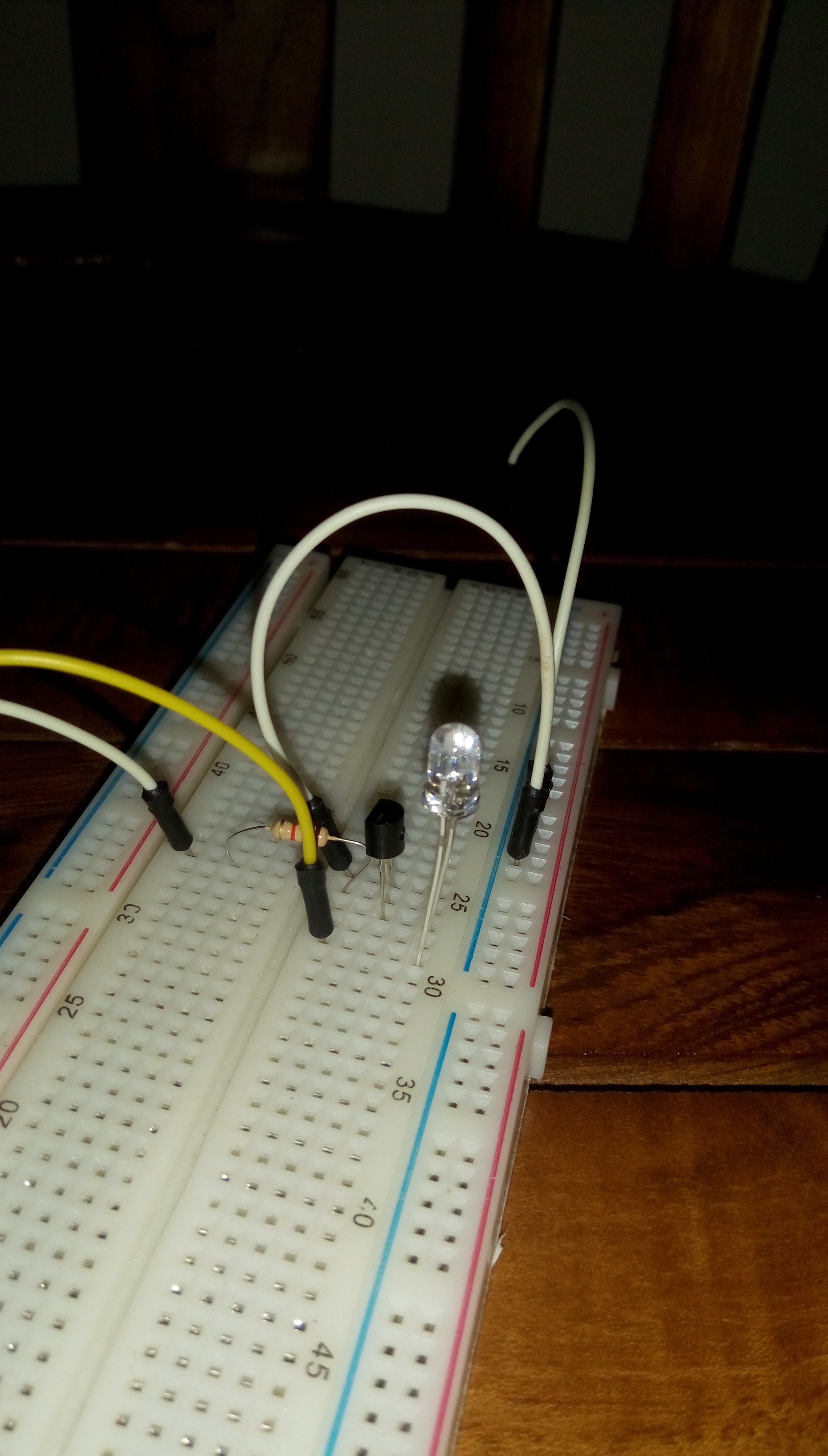
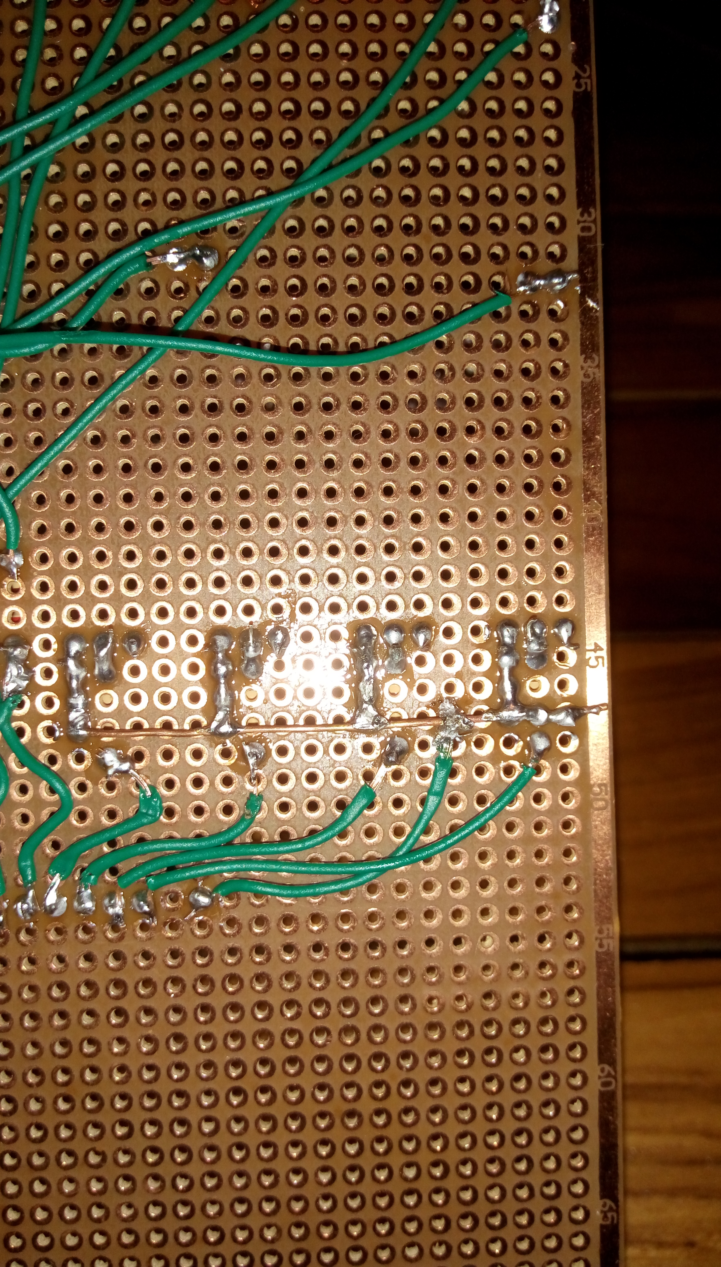
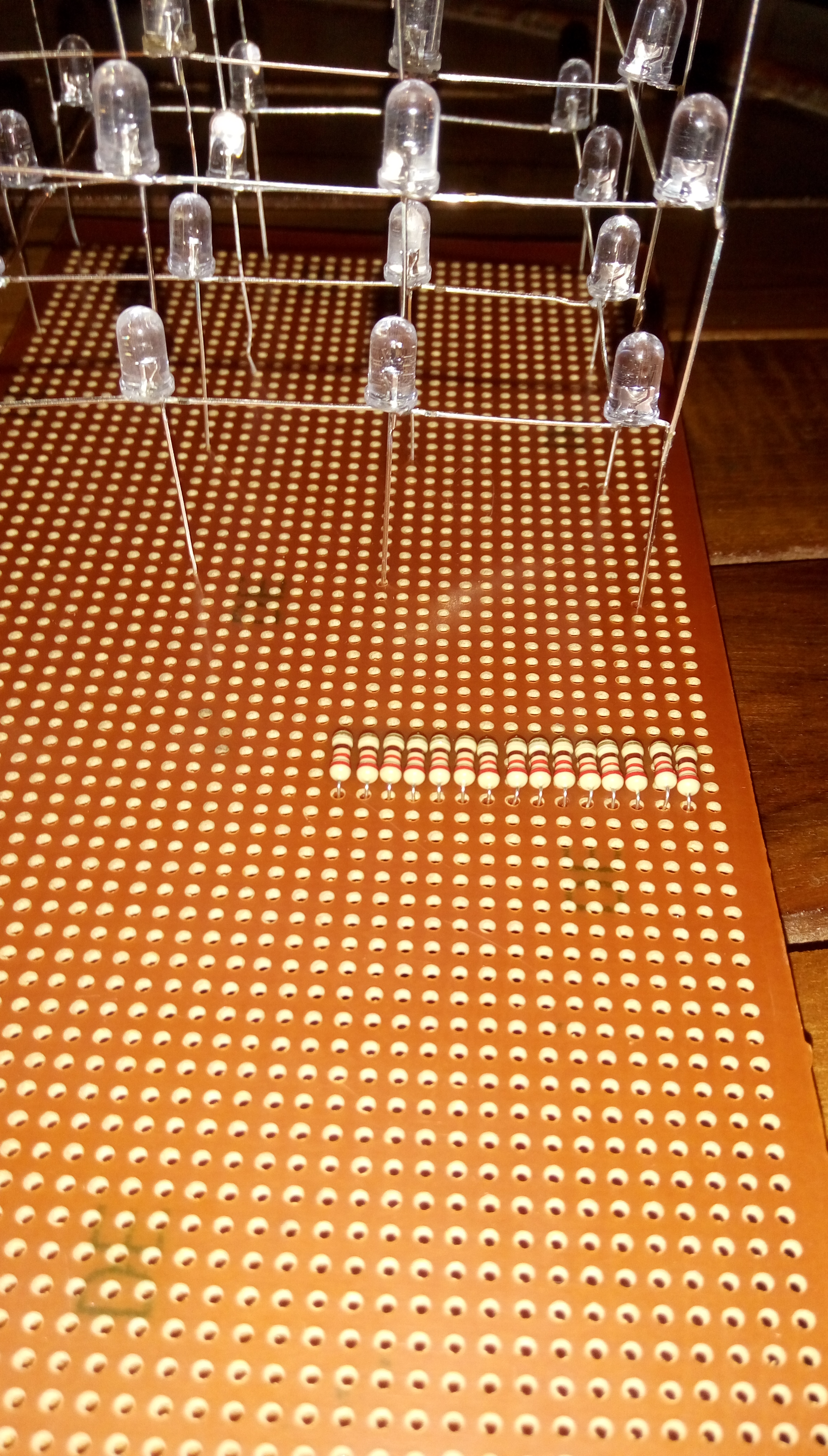
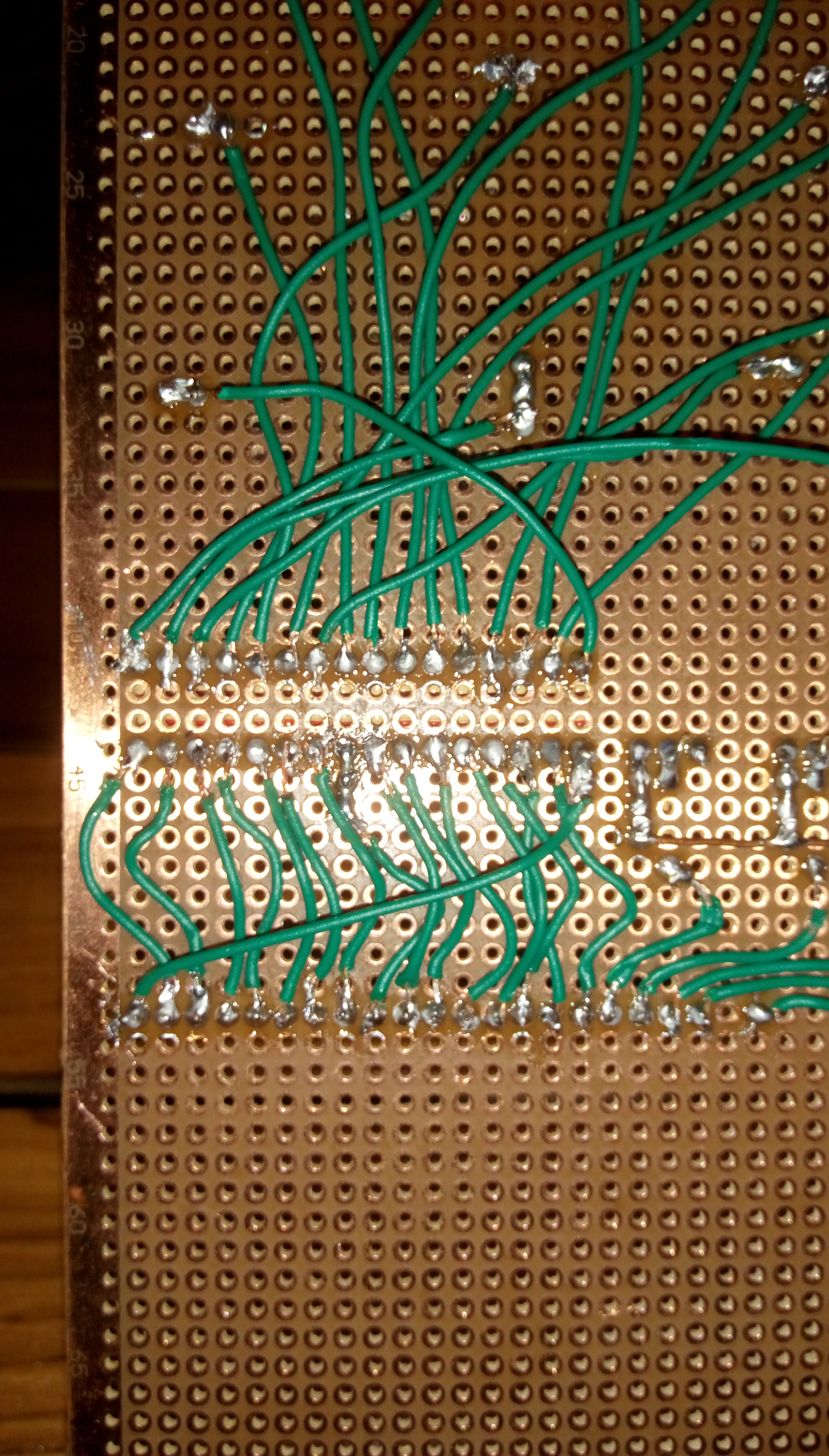
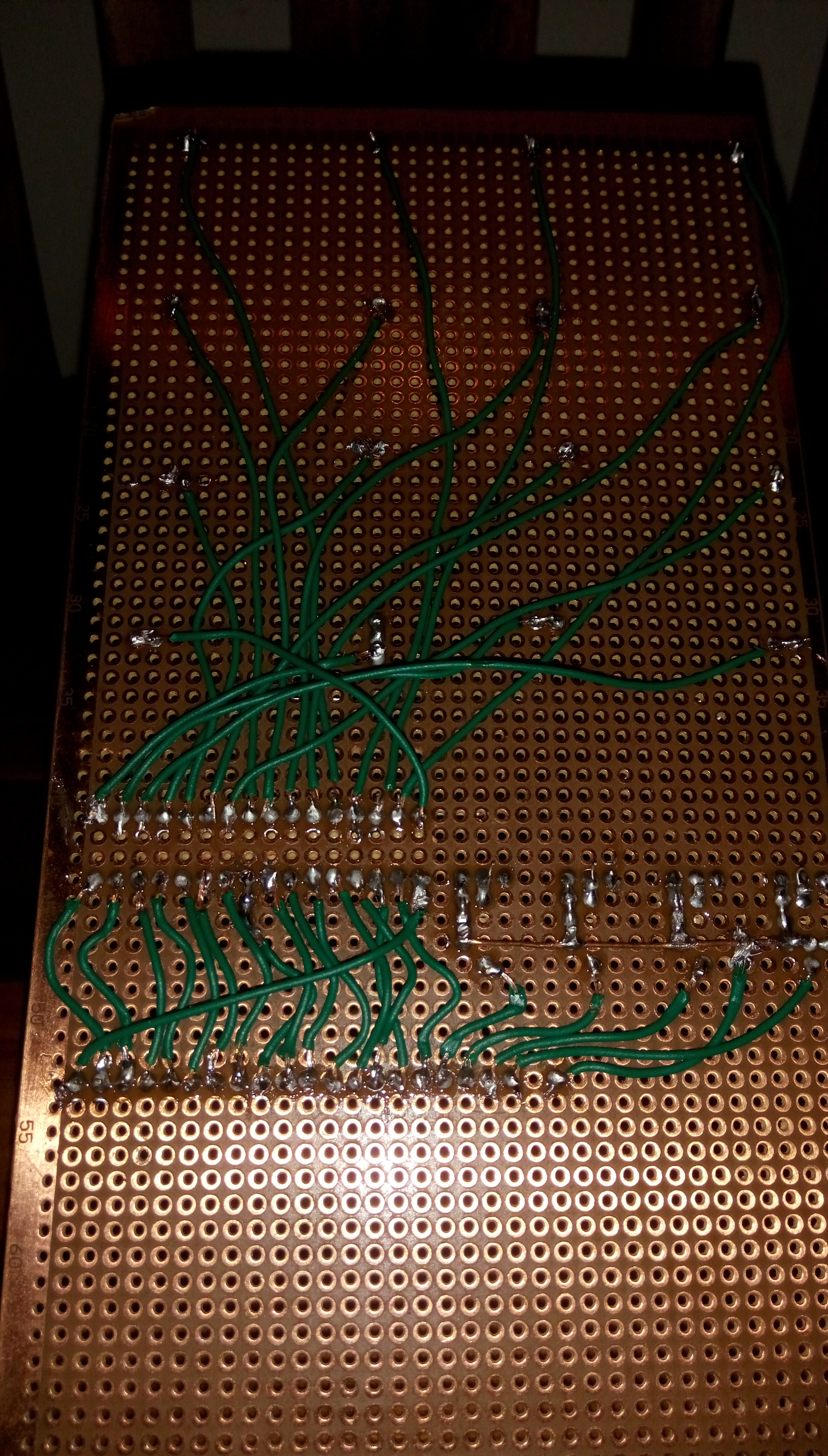
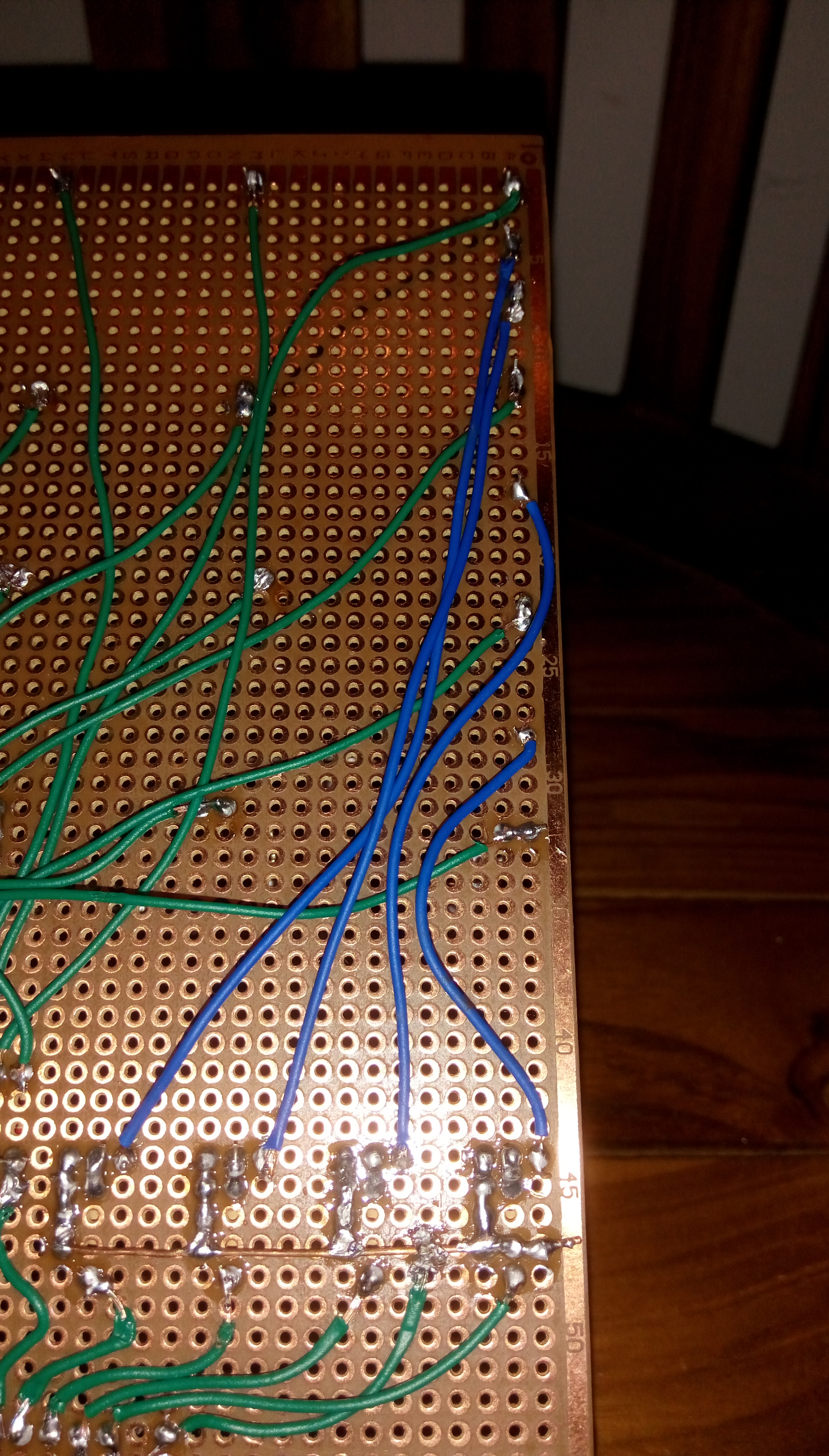
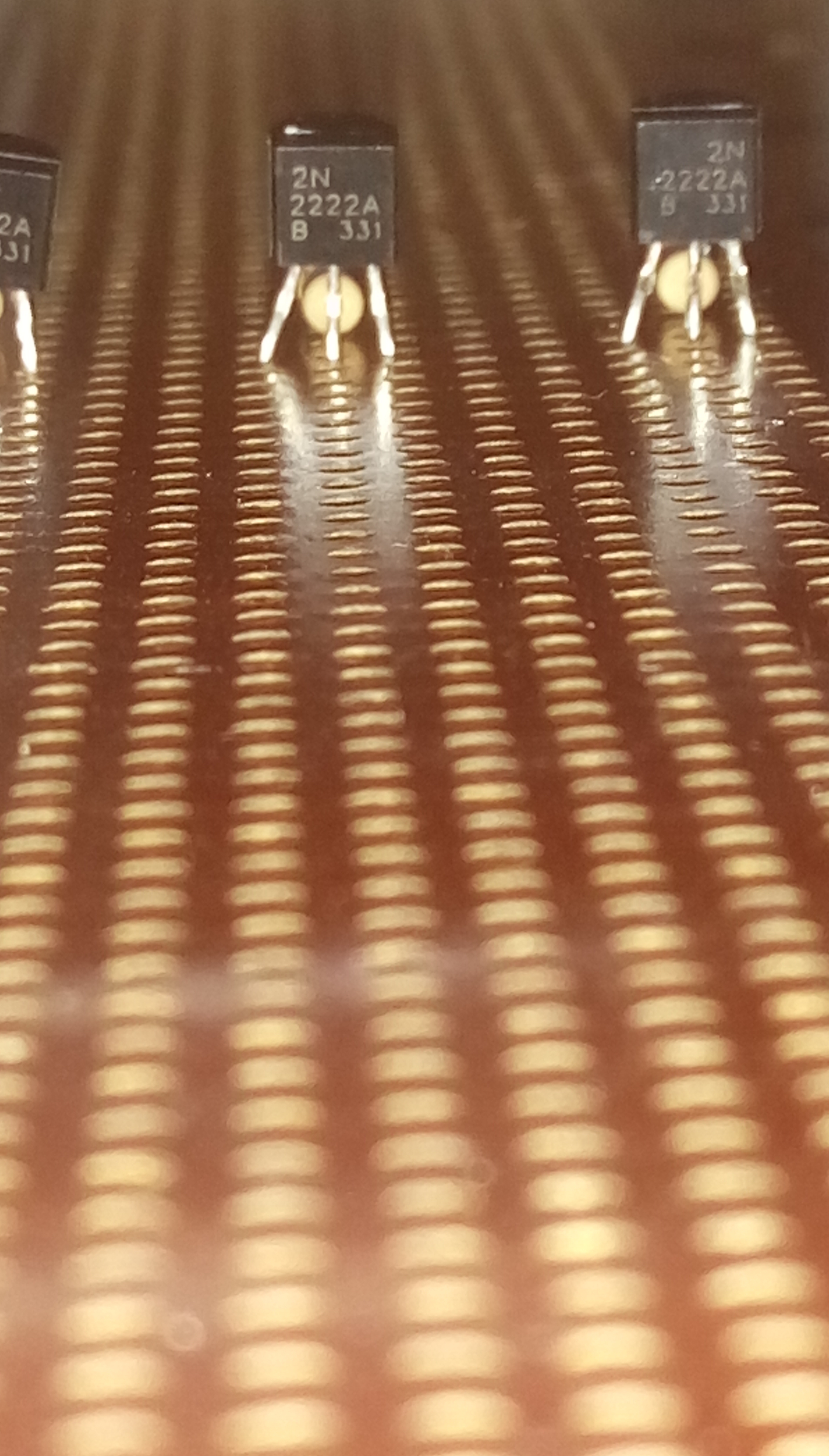
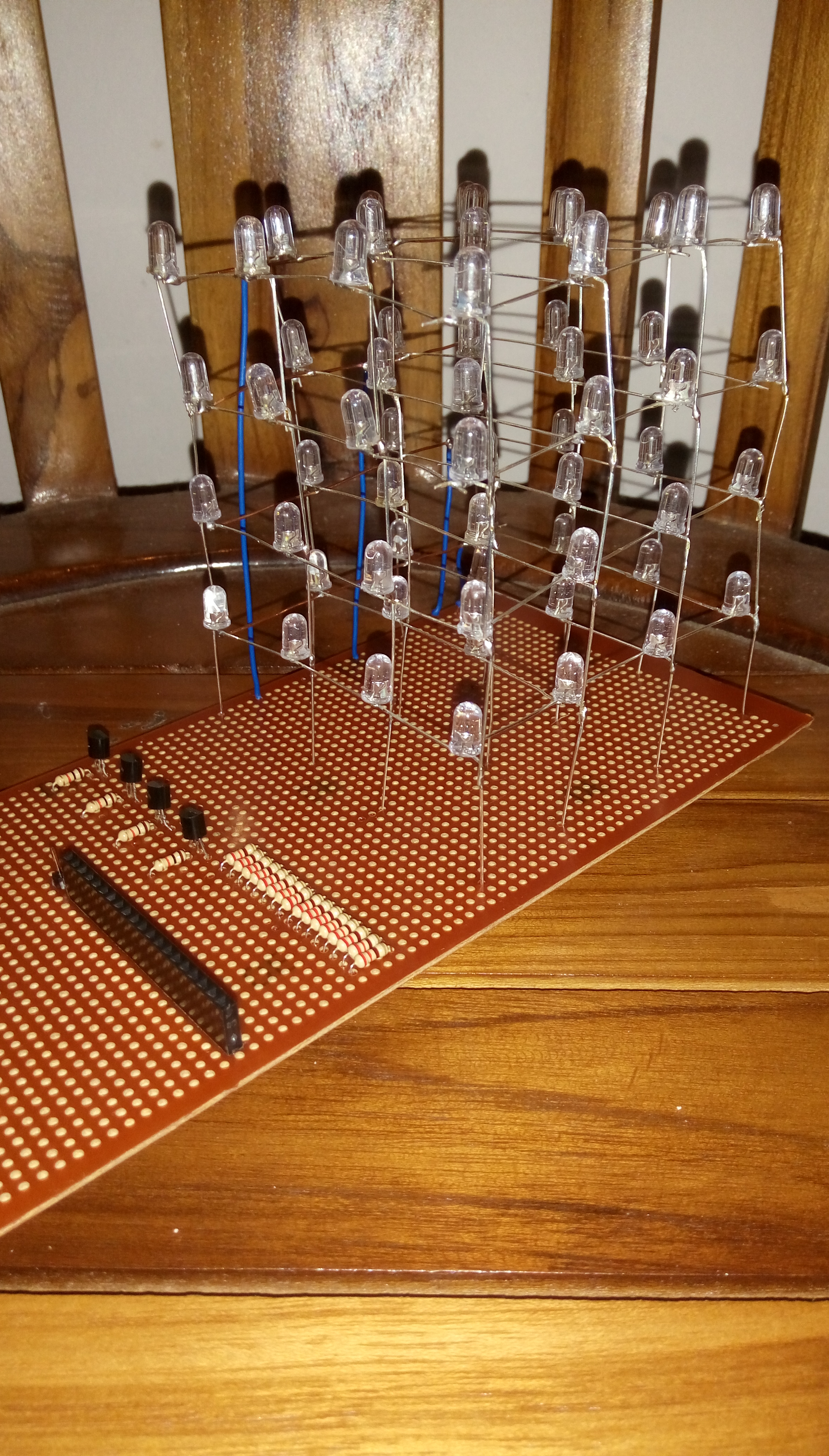
After soldering the cube to the PCB as shown in the pictures, it is time to solder the rest of the circuit.
This includes soldering the 220 OHM resistors to the anodes, soldering the transistor circuits to drive the cathode layers of the cube and soldering all those leads to a female header.
Also, before soldering I think it is best to test it in a breadboard.
Arduino Connections
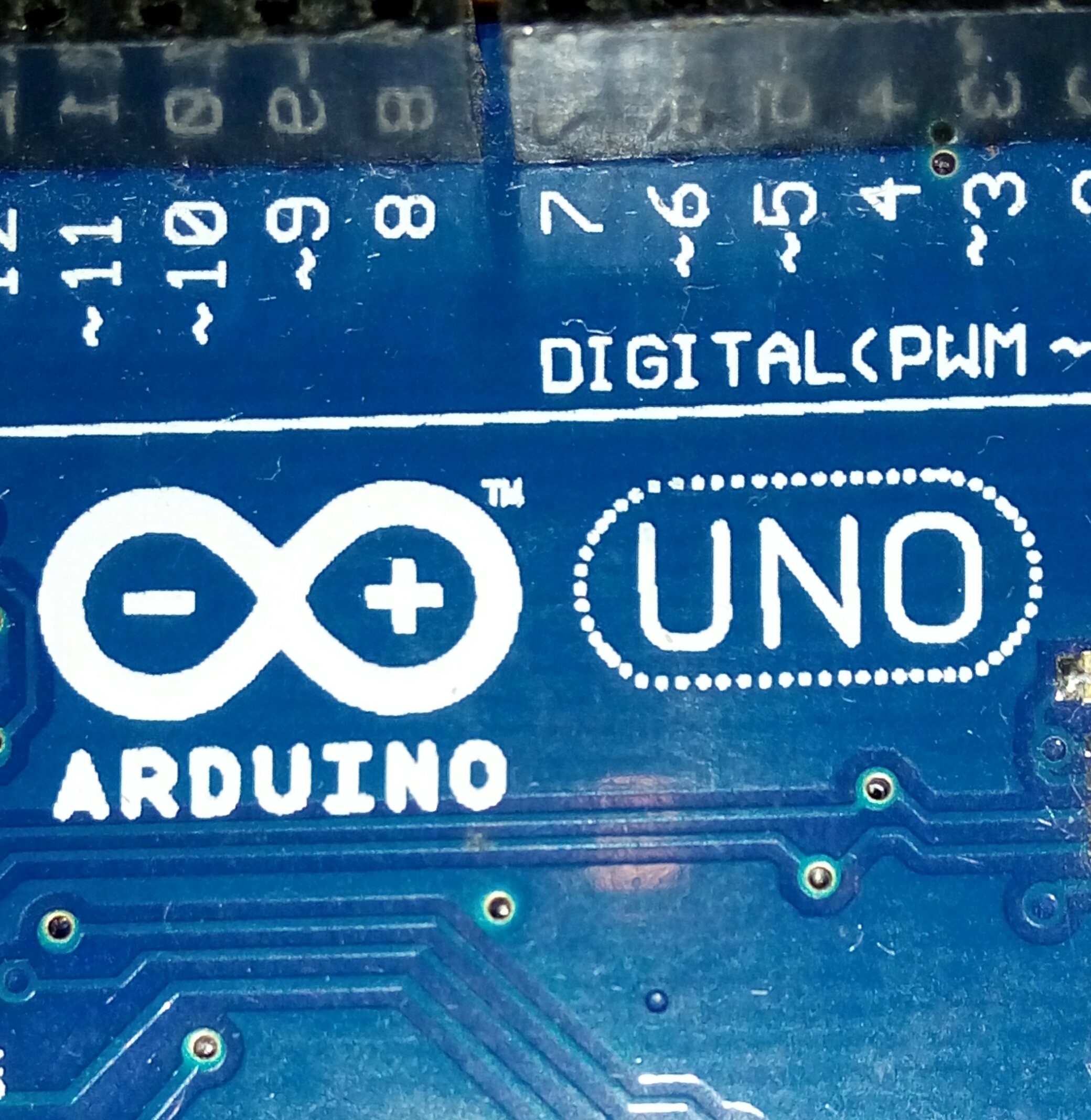
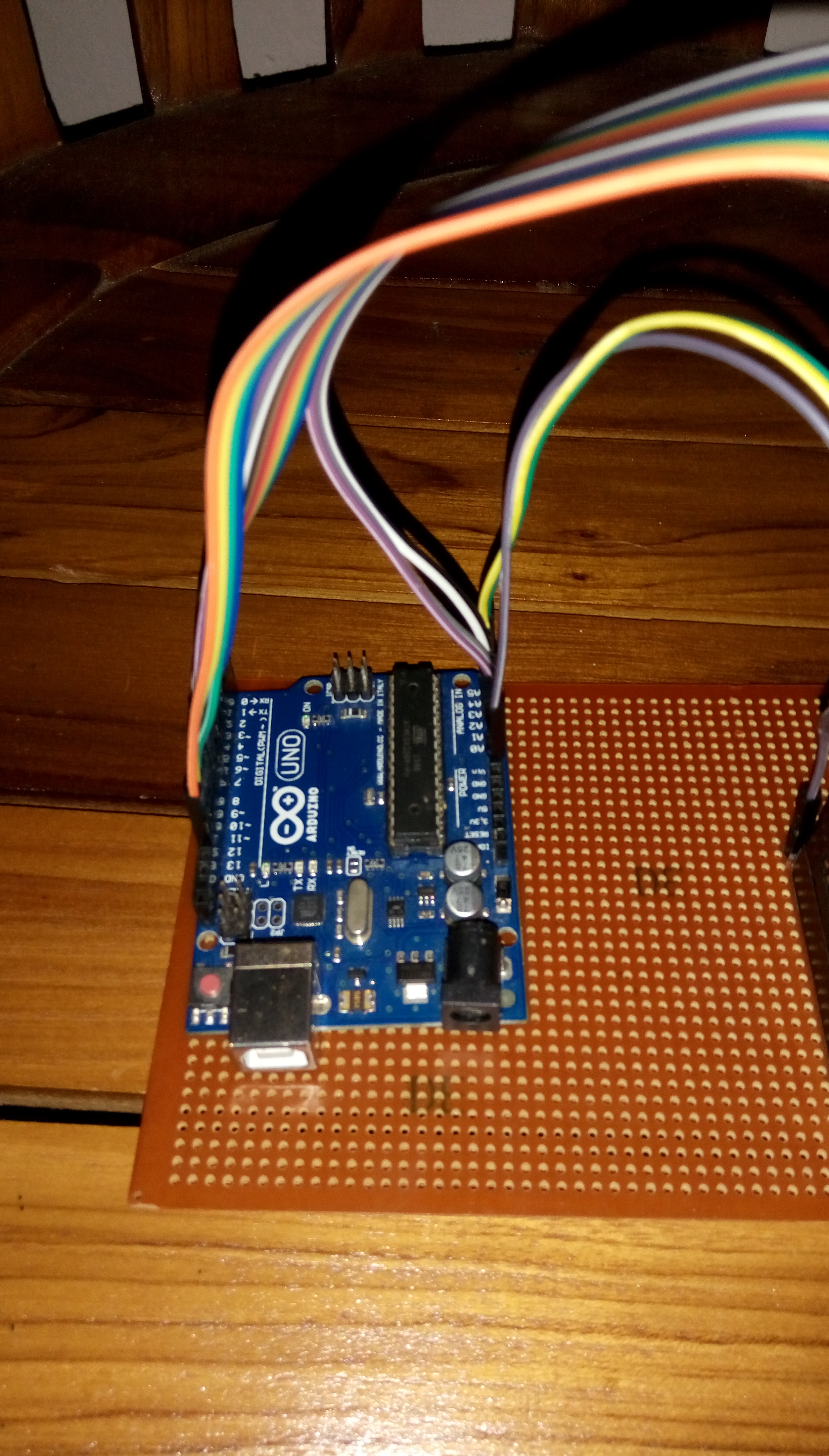
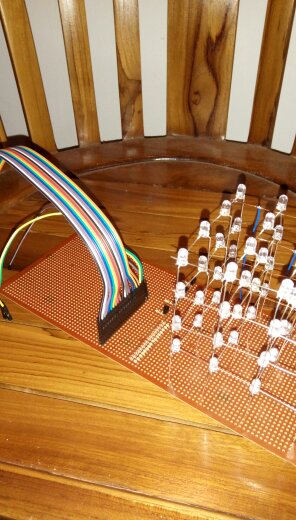
Pretty much all the pins of the arduino uno is going to be used.
The pin connections are as follows
- C16 - D13
- C15 - D12
- C14 - D11
- C13 - D10
- C12 - D9
- C11 - D8
- C10 - D7
- C9 - D6
- C8 - D5
- C7 - D4
- C6 - D3
- C5 - D2
- C4 - D1
- C3 - D0
- C2 - A0
- C1 - A1
- L1 - A2
- L2 - A3
- L3 - A4
- L4 - A5
Coding

First you need to have your Arduino IDE installed,you can find it in the main software page in the Arduino website or just click on this link.
Here is a guide that would walk you through the steps on how to install the Arduino IDE.
The LED Sequence code is a simple and easy way of coding. you can control columns and layers by simply calling digitalWrite functions. The LED cube show code is another interesting one that fades and blinks together.
Below, is a simple code that I have broken down to parts to teach you how it works,
//LED CUBE code
int C1 = 13;
int C2 = 12;
int C3 = 11;
int C4 = 10;
int C5 = 9;
int C6 = 8;
int C7 = 7;
int C8 = 6;
int C9 = 5;
int C10 = 4;
int C11 = 3;
int C12 = 2;
int C13 = 1;
int C14 = 0;
int C15 = 14;
int C16 = 15;
int L1 = 16;
int L2 = 17;
int L3 = 18;
int L4 = 19;
This piece of code initializes the columns and layers to the digital and //analog pins in the Arduino UNO. C stands for columns and L stands for layers.
void setup() {
  pinMode(C1, OUTPUT);
  pinMode(C2, OUTPUT);
  pinMode(C3, OUTPUT);
  pinMode(C4, OUTPUT);
  pinMode(C5, OUTPUT);
  pinMode(C6, OUTPUT);
  pinMode(C7, OUTPUT);
  pinMode(C8, OUTPUT);
  pinMode(C9, OUTPUT);
  pinMode(C10, OUTPUT);
  pinMode(C11, OUTPUT);
  pinMode(C12, OUTPUT);
  pinMode(C13, OUTPUT);
  pinMode(C14, OUTPUT);
  pinMode(C15, OUTPUT);
  pinMode(C16, OUTPUT);
  pinMode(L1, OUTPUT);
  pinMode(L2, OUTPUT);
  pinMode(L3, OUTPUT);
  pinMode(L4, OUTPUT);
}
This the SETUP of the code.This is where you declare the column and layer pins as OUTPUTS
by the pinMode" function.
void loop() {
//This is where you type exactly how the LEDS should light up.
//For example, if you type ,
digitalWrite(L1,HIGH);
delay(500);
digitalWrite(L1,LOW);<br>delay(500);
//the Layer 1 should be on for half a second and turn of and at that time,
//if any of the columns were on those columns in the Layer 1 should have lit up.
//For example,
digitalWrite(L1,HIGH);
digitalWrite(C1,HIGH);
digitalWrite(C5,HIGH);
digitalWrite(C9,HIGH);
digitalWrite(C13,HIGH);
delay(500);
digitalWrite(L1,LOW);
delay(500);
//You are welcome to try this out.Copy it in your Arduino IDE and edit it in your own way!.Success!
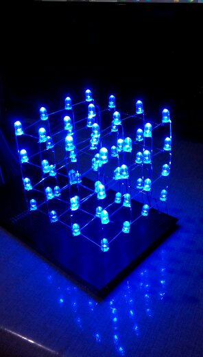


I hope you liked this instructable, if so please be kind to vote for me on the First Time Author Contest.
Here are some links to other cube builds,
- www.instructables.com/id/4x4x4-LED-Cube-Arduino-Uno/
- www.instructables.com/id/4X4X4-LED-Cube-w-Arduino-Uno/
- https://create.arduino.cc/projecthub/ihassanibrahim7/voice-controlled-led-cube-with-arduino-uno-and-1sheeld-69afc2
- http://tutorial.cytron.com.my/2015/08/17/4x4x4-led-cube-using-arduino-uno-without-extra-ic/