Lets Build "Cubism Gal" Part 3
by PAUL EASTHER Artisan in Workshop > CNC
274 Views, 0 Favorites, 0 Comments
Lets Build "Cubism Gal" Part 3
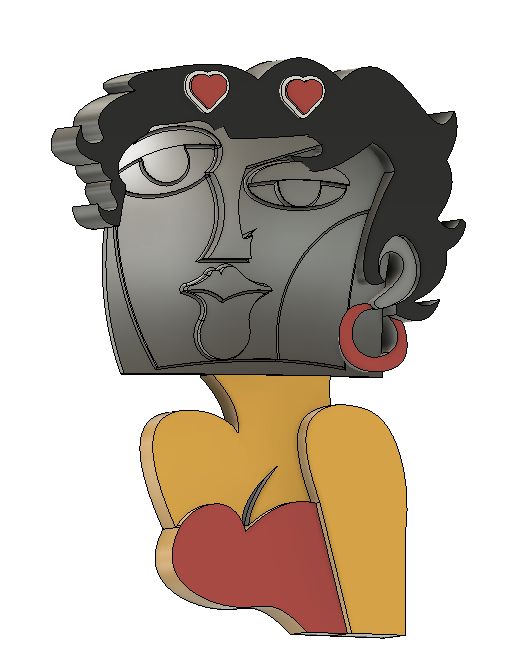
Part 3, of what I reckon will probably need 6 parts to complete the task!! With these types of complex shapes I reckon that 4 times more time goes into the design and writing CAM procedures, than the actual machining. CNC is really all about mass production for economies of scale. One offs like "Cubism Gal" are more for the love of it. I suppose I could record a video with all the steps involved compressed into 15 minutes? It would have to run at a mega pace to fit everything in. There are videos like that on the Net, and my experience is that they're like watching a F1 car race....you don't learn anything about driving!
First CAM Procedure
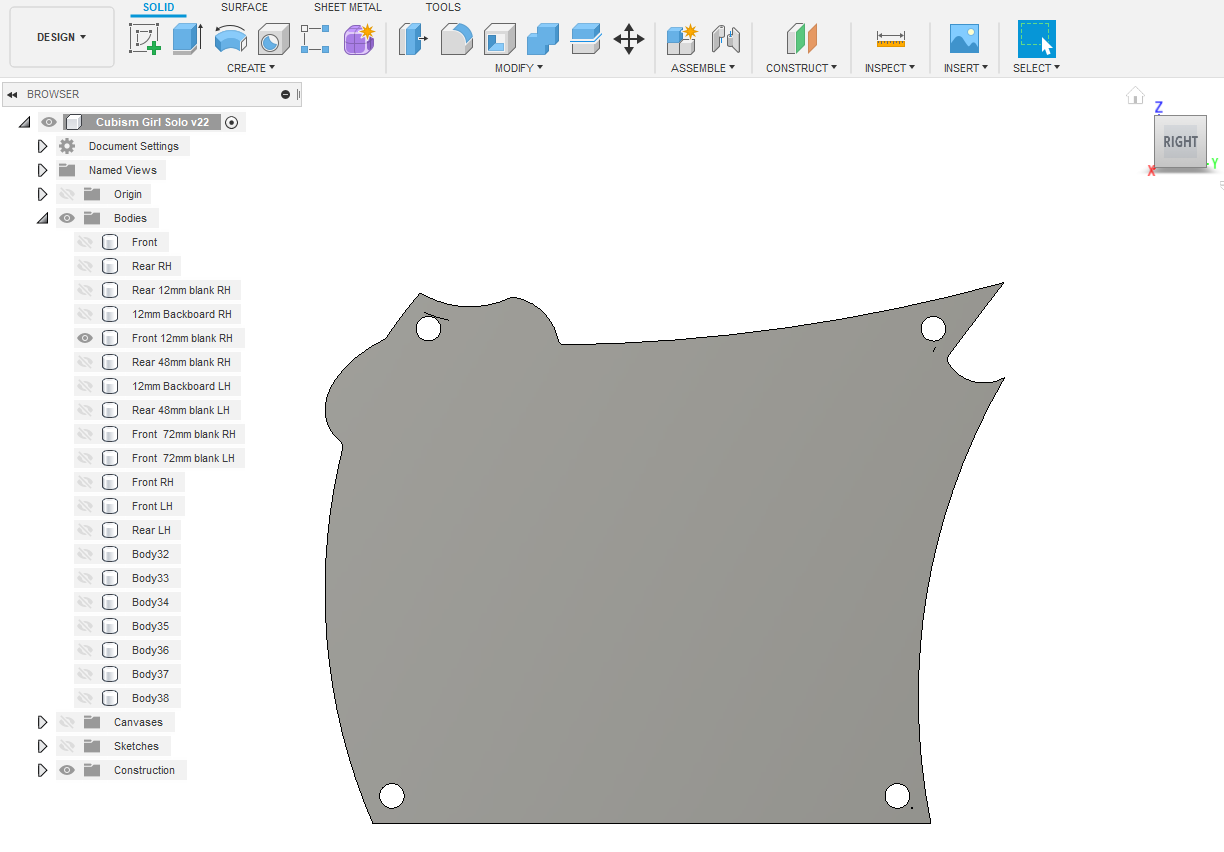
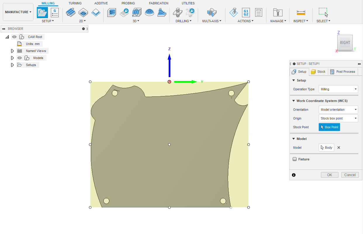
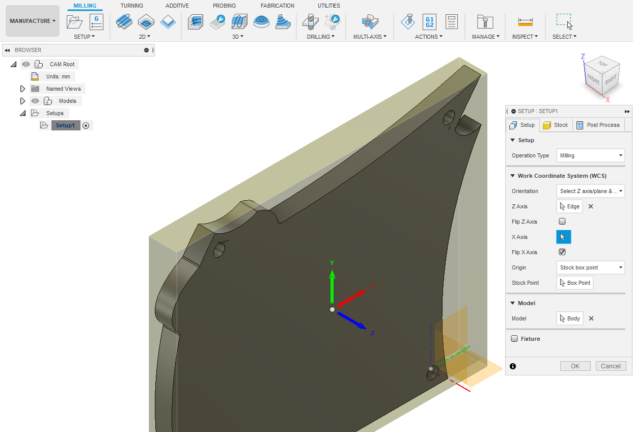
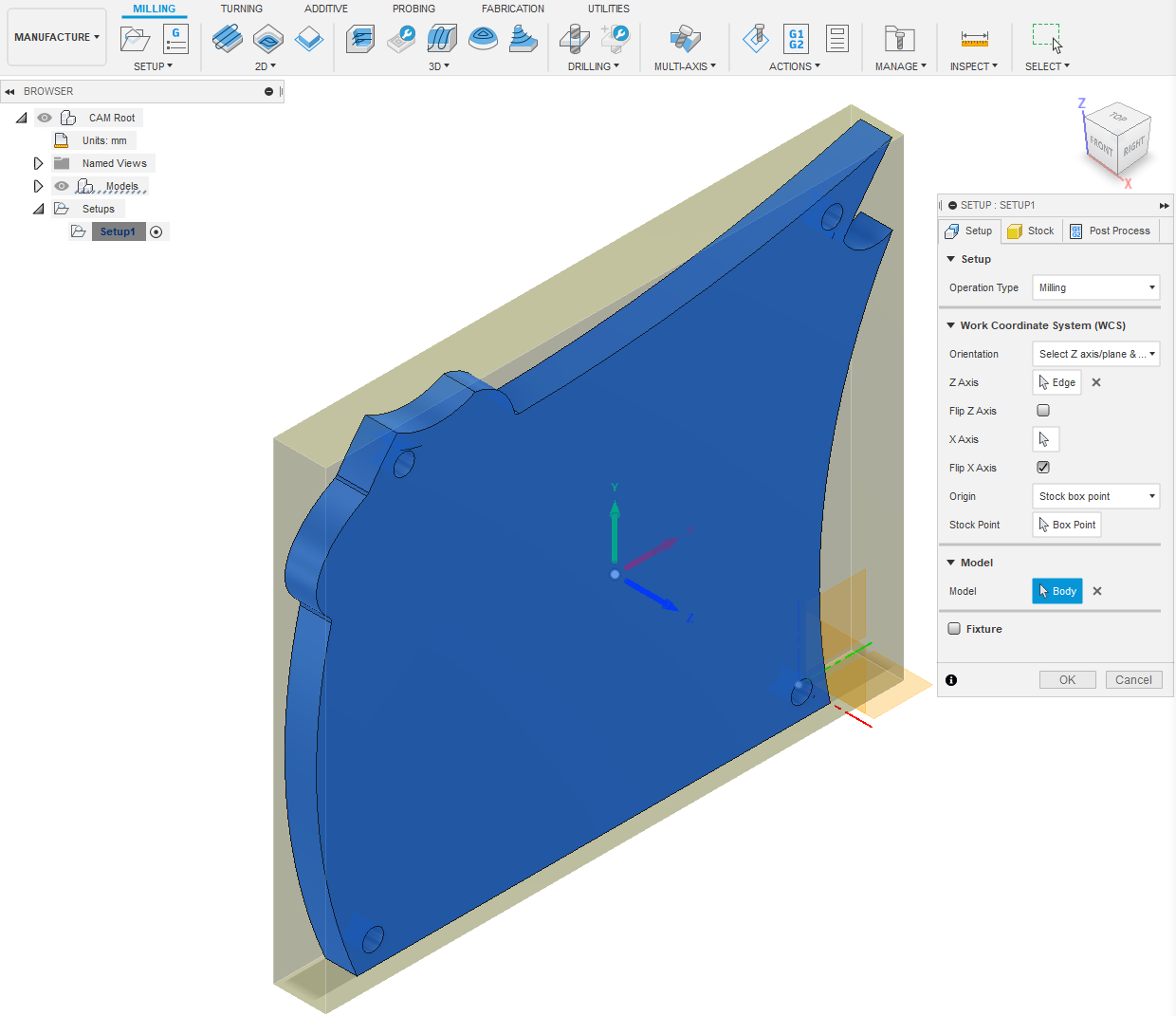
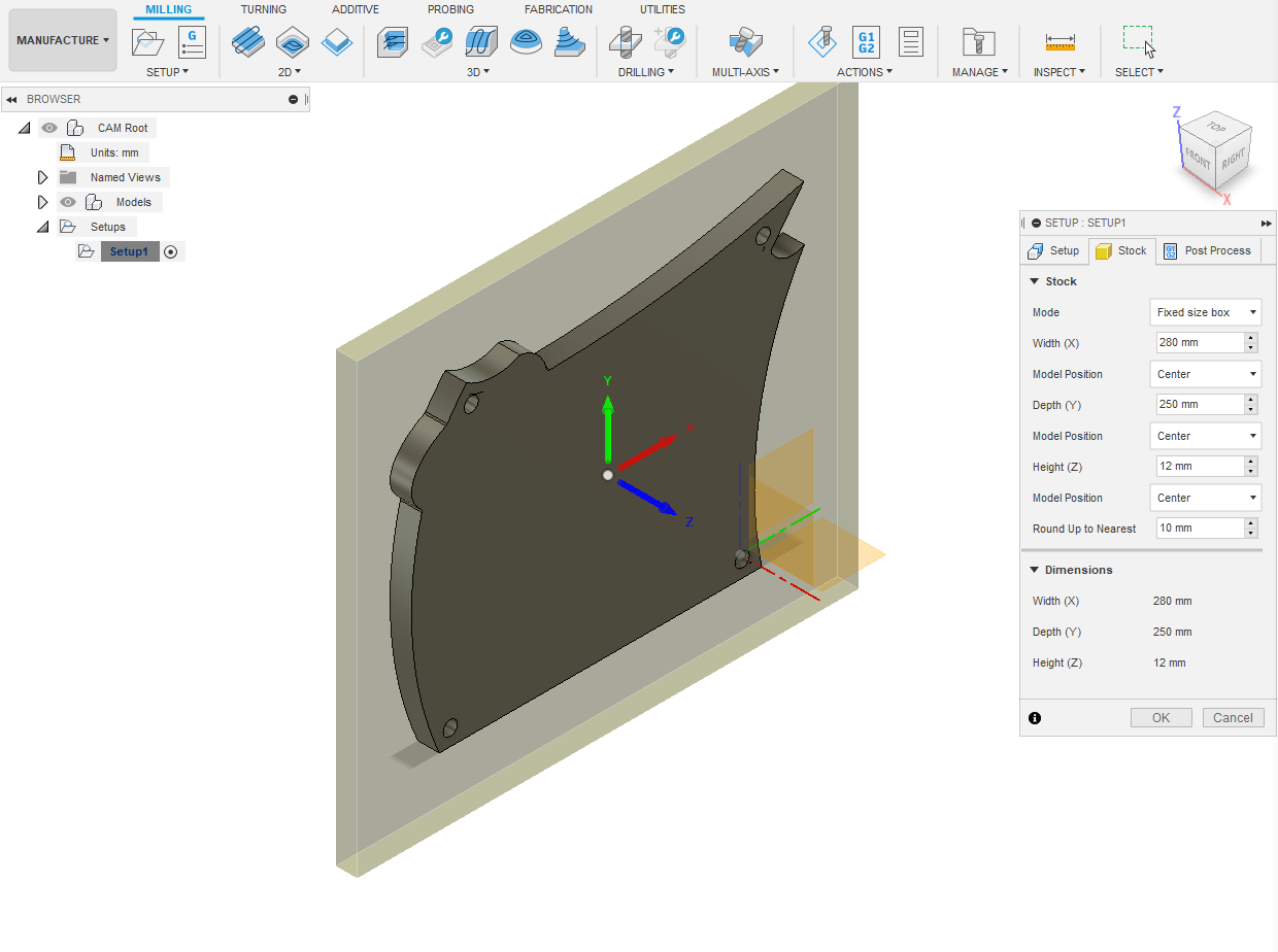
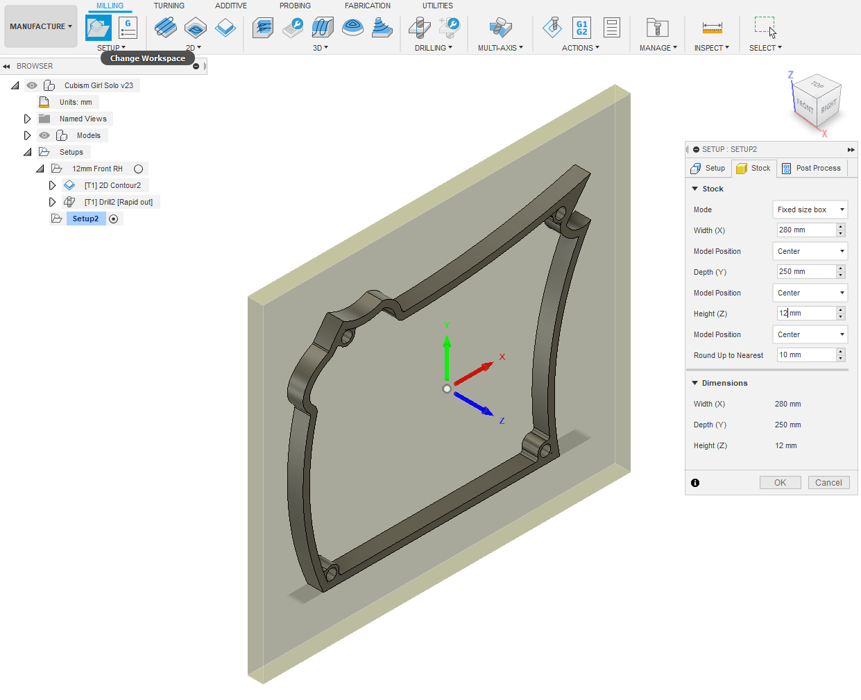
Firstly, we'll write the CAM operations to cutout the 12mm blanks and backboards. Start with Front 12mm blank RH by selecting it from tree. Select MANUFACTURE - SETUP - New Setup - OK. Right click Setup1 - Edit.SETUP : SETUP1 popup appears. Operation Type is Milling. Select Stock tab. Mode is Fixed size box. Click Setup tab again. Orientate the body to be isometric by clicking the House symbol next to the top RH cube. Select Orientation - Select Z axis/plane &... The Z axis is vertical to face of body. With mouse pointer click a 12mm height edge. X axis should point towards the right, at the moment it's pointing left. Click the box next to Flip X Axis. The XYZ origin has located it's self on the centroid of the notional rectangular blank that surrounds Front RH. For our purposes that's an easy registration mark for the CNC setup. In the popup Model select by clicking the body Front RH in the isometric view.
Re click Stock tab in popup. Make Width (X) 280mm. Depth (Y) 250mm Height (Z) 12mm - OK. Rename Setup1 - Setup 12mm FrontRH
Cutout Front 12mm Blank RH Part 1
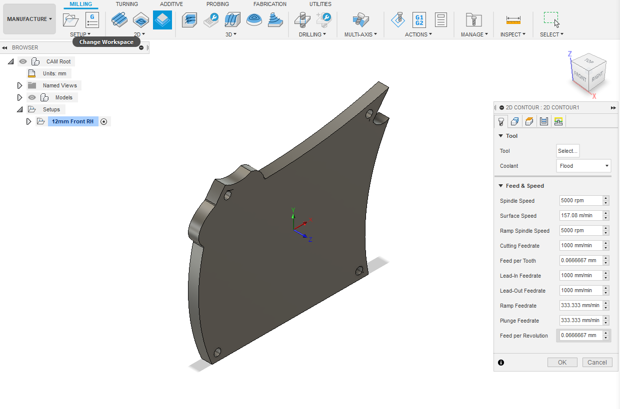
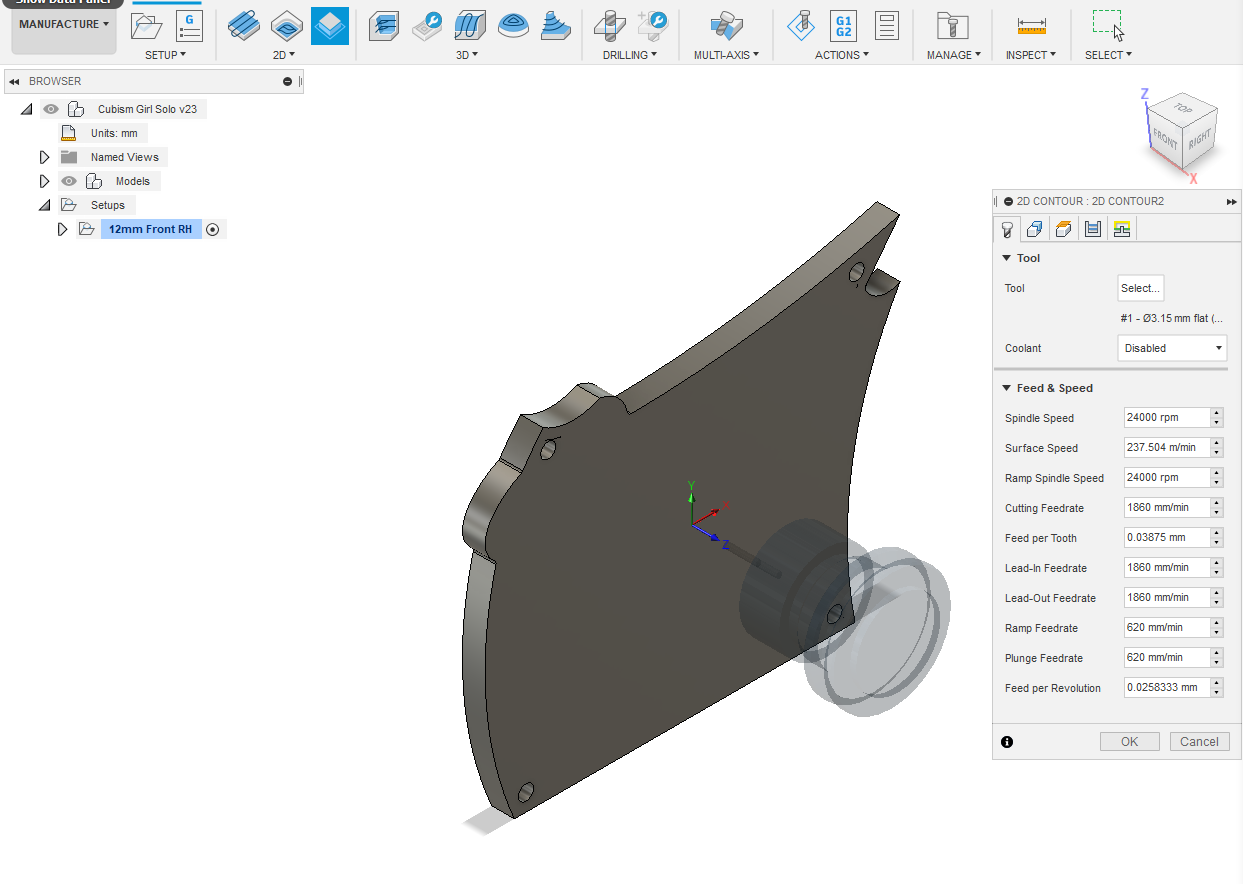
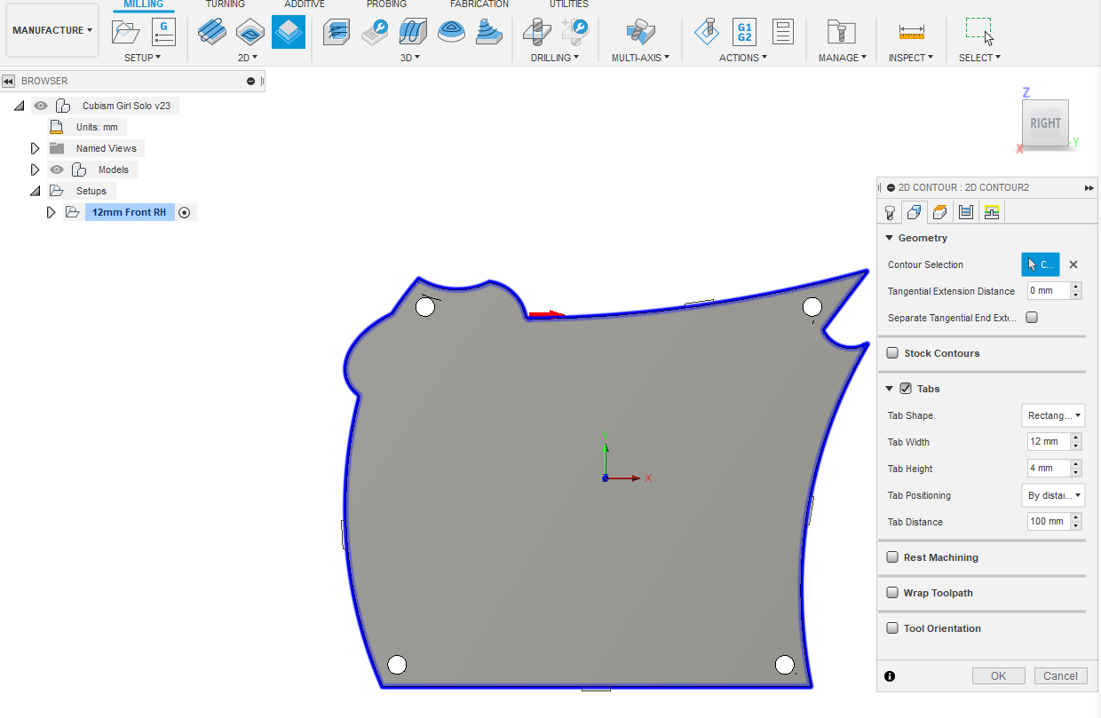
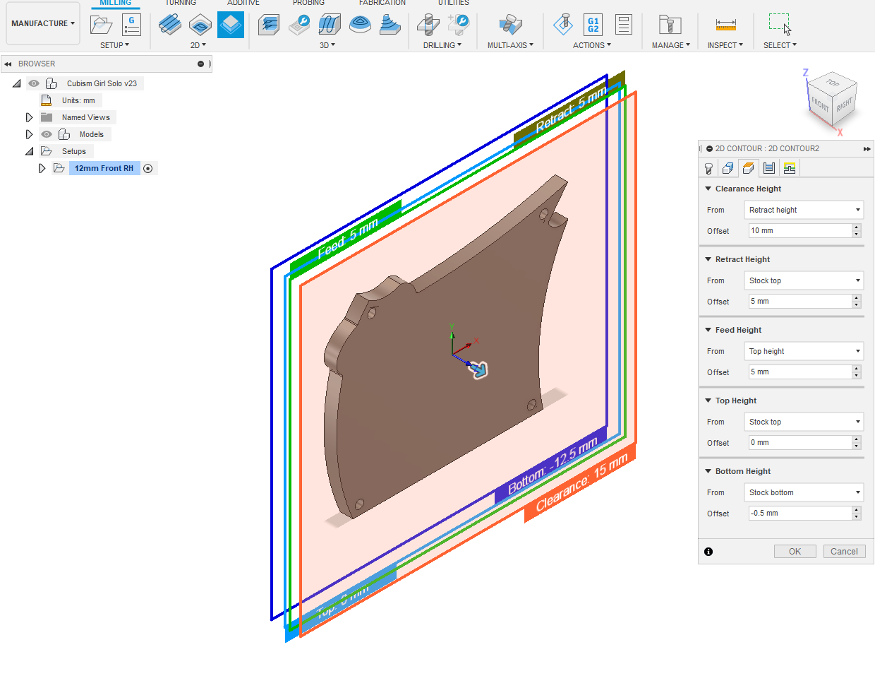
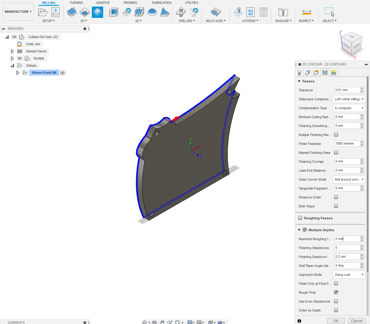
Select 2D - 2D Contour from Milling menu. A popup 2D CONTOUR : 2D CONTOUR1 appears. Select Tool by going to your tool library. I selected a 3.175mm dia Flat end mill.
Now setting up your Tool Library is a whole new ball game and outside the scope of this Instructable. There is plenty of info, both within Fusion and on the Net about how to do that? I'll just say one thing though, "When adding a new tool have a micrometer handy. Just because a tool is marked 6mm doesn't mean it is! It might be 5.88 mm dia. A micrometer or vernier calipers will tell you that?" Insert the actual dimensions of your tools.
Coolant is Disabled as we're milling mdf. Your Feed & Speed info will be preloaded with your tool selection. Select next tab in popup Geometry. In Contour Selection use mouse pointer to select bottom outside edge. That little red arrow above the blue contour line should be on the outside of the line. If it isn't just click it. Click Tabs. Tab Shape Rectangle. Change auto suggestions to Tab Width 12mm Tab Height 4mm Tab Distance 100mm.
Click next tab in popup Heights. In Bottom Height change From to Stock Bottom and Offset to -0.5mm. This ensures a clean cut through of the body by 0.5mm. You'll need to have a piece of scrap mdf under your blank, without it you'll have carvings into your CNC bed.
Click next tab Passes. Click Multiple Depths Max Roughing Stepdown make 2mm - OK.
Of course, everything I have just done is a variable. You could cut this out with a 12mm flat end mill if you choose to and everything will change selection wise. You'll learn and make do with whatever tools you've got.
Cutout Front 12mm Blank RH Part 2
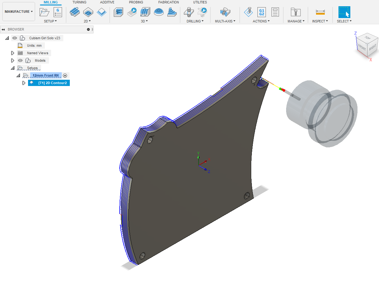
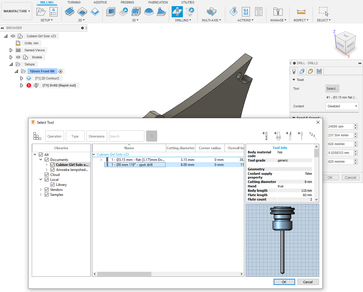
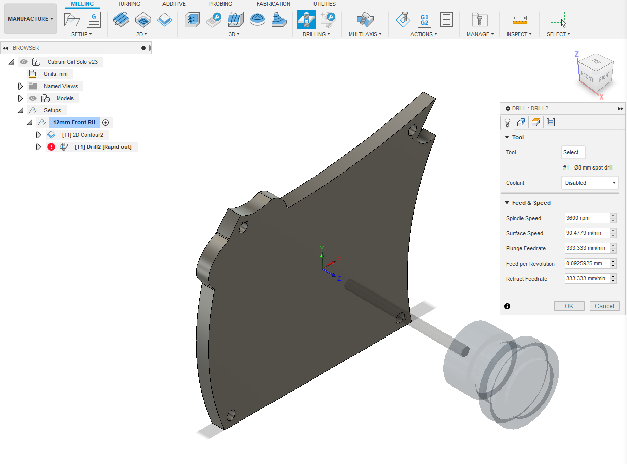
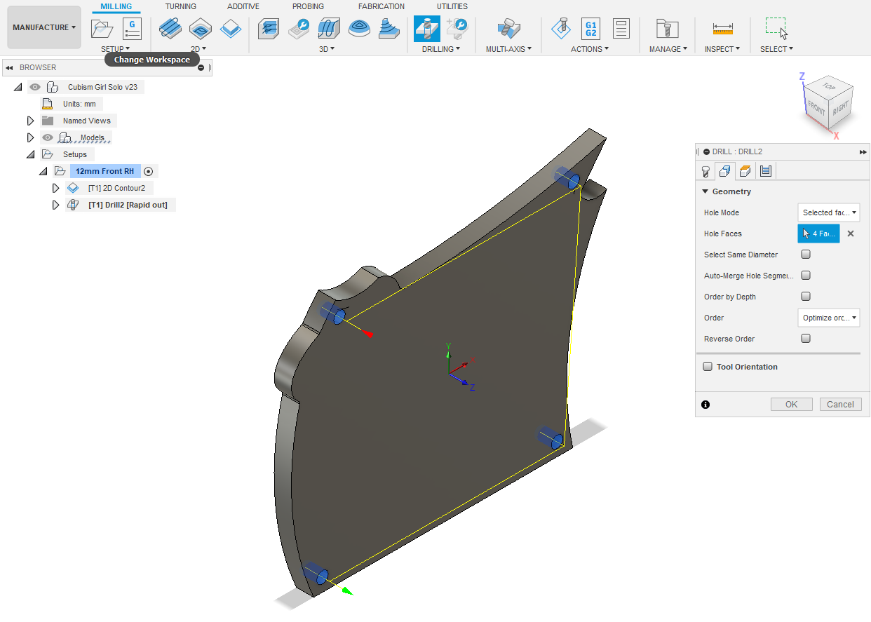
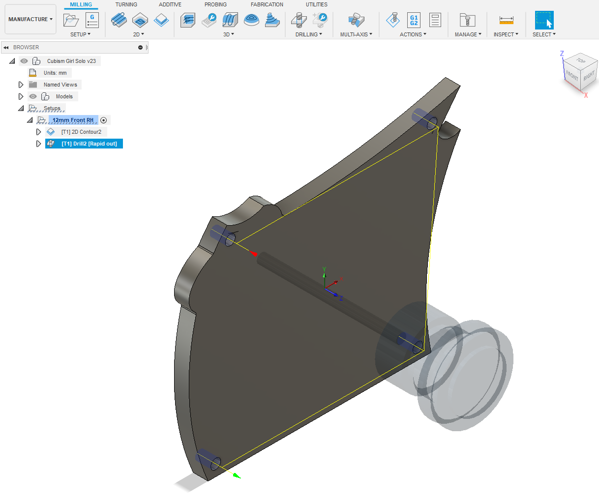
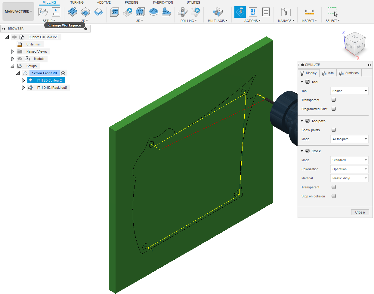
Once we click the final OK in the popup we're presented with a tool path depiction. Take a close look at it for any glaring errors? Note that a new operation name has appeared [T1] 2D Contour2
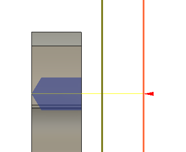
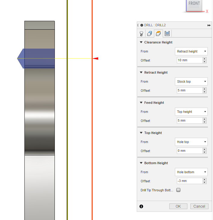
Next we drill the holes. Click DRILLING - Drill from MILLING selections. A popup appears. Select 8mm spot drill - OK. Disable Coolant. Click Geometry tab. Use mouse pointer and select inside hole faces. Click Heights tab. Click FRONT on orientation cube in top RH corner. You'll see the blue visualization of the drill and it doesn't drill cleanly through your blank? Under Bottom Height change Offset to -3mm - OK
Click the House symbol next to the orientation cube. You should be looking at the toolpath for the drill?
Time for a simulation? Right click on 12mm Front RH in the tree - Simulate. Click Stock in popup. Hit the big arrow centre bottom of screen. I've included a screencast of the two operations combined. After viewing your simulation, if everything looks OK, then click ACTIONS - Post Process. Give this operation a Program name and Post to a USB storage device. You are now ready to connect with a CAM software program like UCCNC and cutout your blank.
Downloads
Cutout Rear 12mm Blank RH
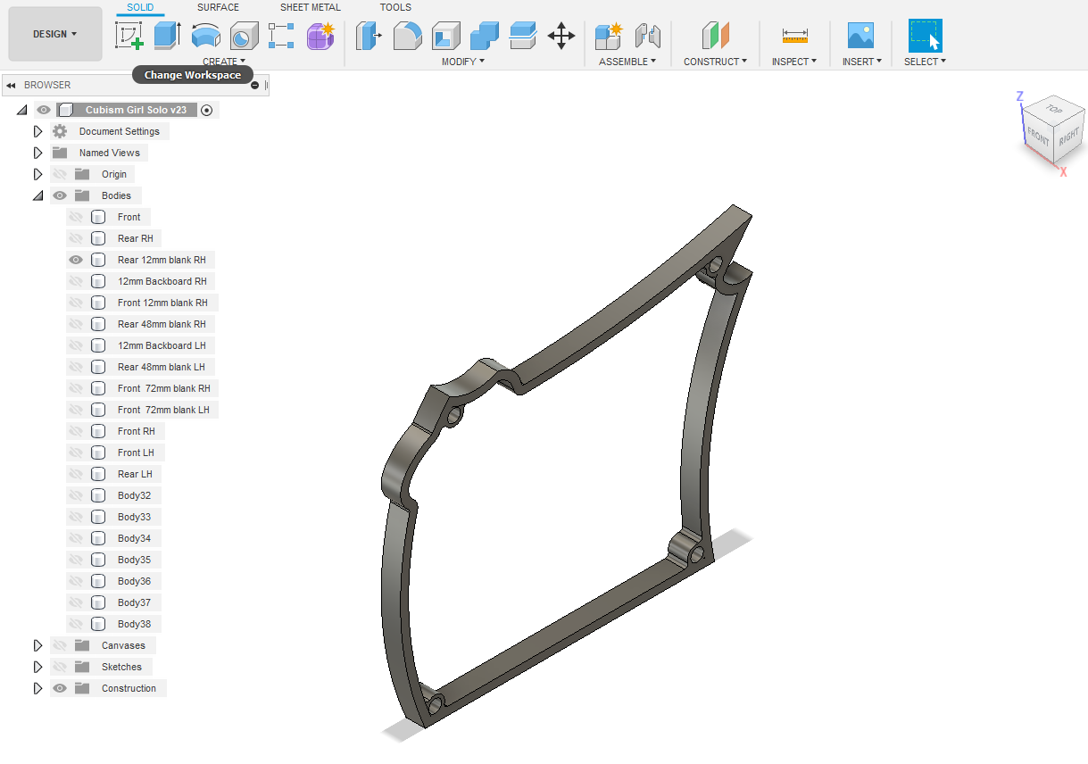
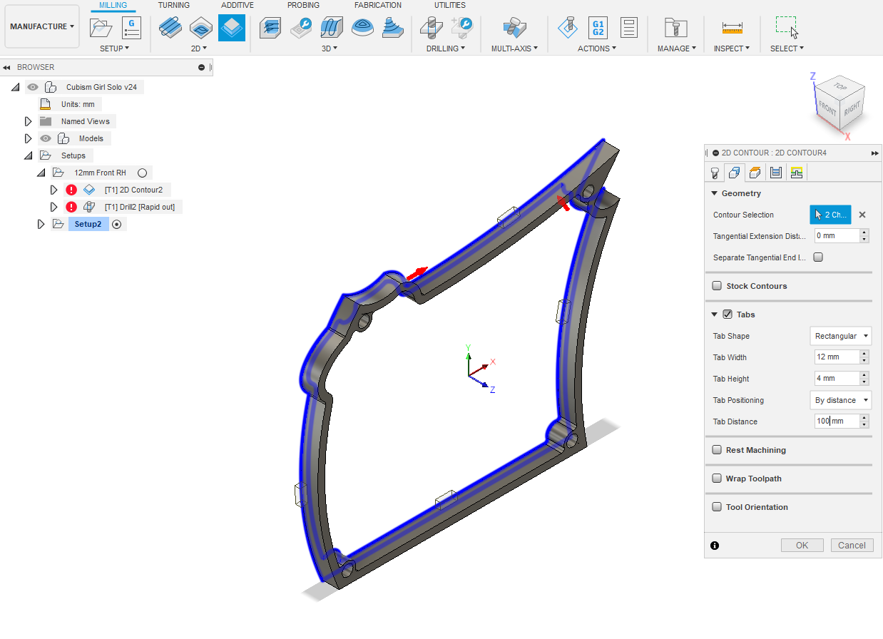
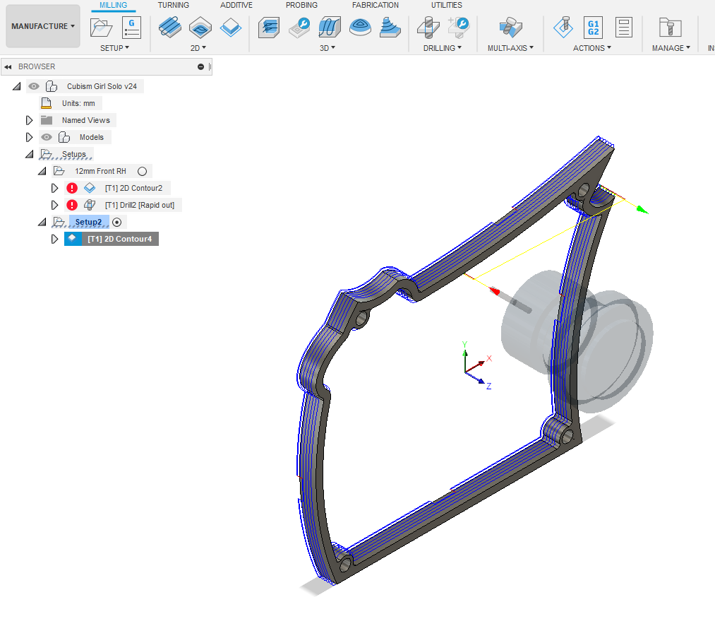
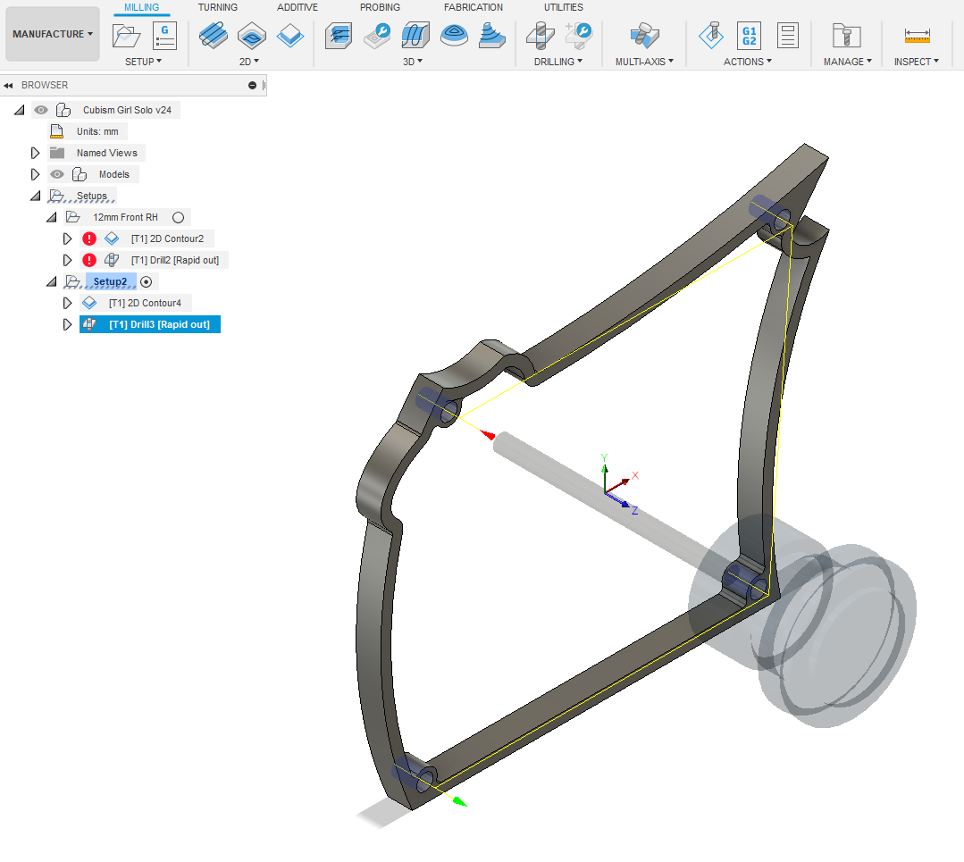
Everything you have just done for Front 12mm blank RH cutout will be repeated for Rear 12mm blank RH. I won't go through all the text again but will include pictures along the way as before.
There's an additional bottom edge contour to select in this body, see pic.
See Recording.
Even though these blanks are designated RH, they are both left and right hand by just flipping them, so no need to make another version. They'll be glued together and flipped before fixing to Backboard.
Downloads
12mm Backboard LH & RH
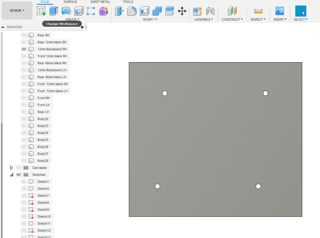
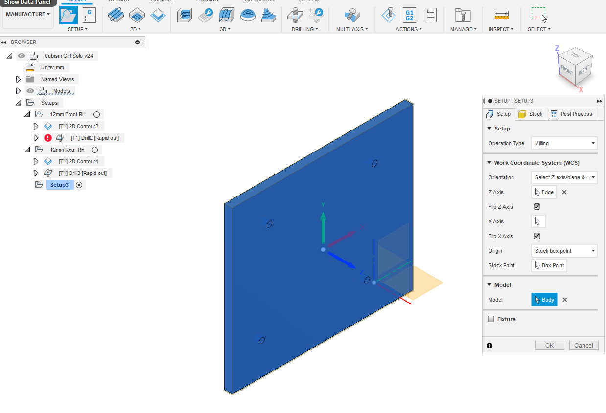
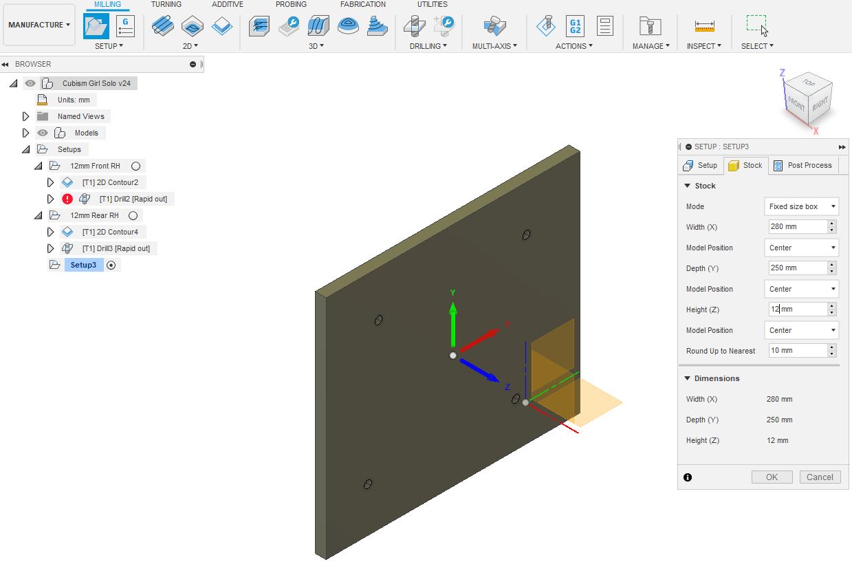
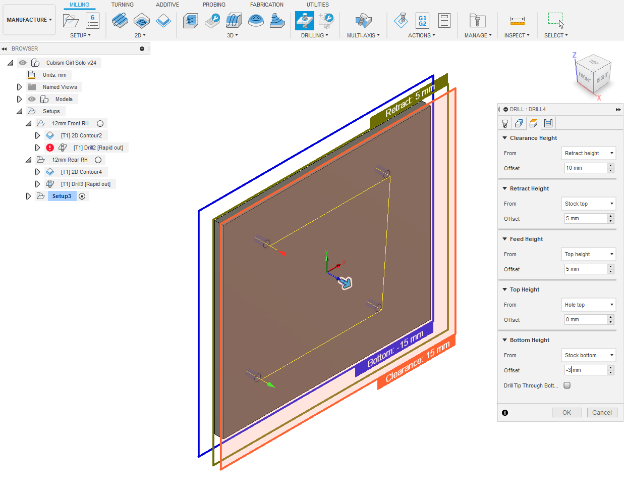
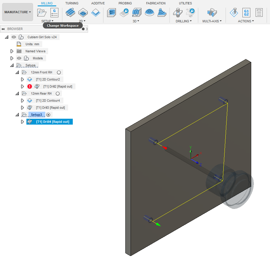
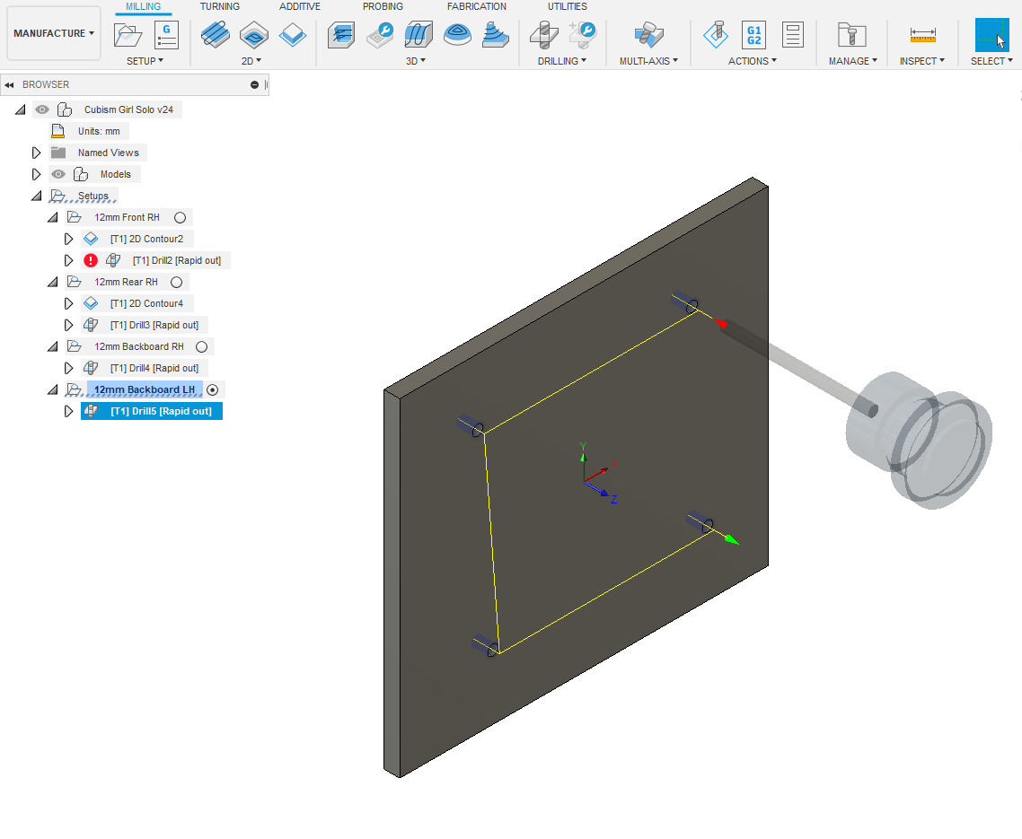
Next we write tool paths for drilling backboards. In DESIGN select 12mm Backboard RH . Select MANUFACTURE. While we're here I notice that I should've renamed Setup2 to 12mm Rear RH. Don't be alarmed by those red and white warning exclamation marks? It's just a Fusion thing! If you revisit that step to amend or look at it, just right click Edit and OK, and they'll disappear.
Click SETUP - New Setup. Orientate the XYZ arrows as in the previous steps. Go to Stock tab and for Mode - Fixed Size Box and Height (Z) to 12mm - OK.
Select DRILLING - Drill and repeat same settings as past operations. Rename Setup3 as 12mm Backboard RH
Go back to DESIGN and select 12mm Backboard LH. Repeat all as above. Post Process to a USB storage device, all these operations.
Don't forget to regularly save your work! You're now ready to physically cut out and glue together your blanks.