Lego Self Driving Car
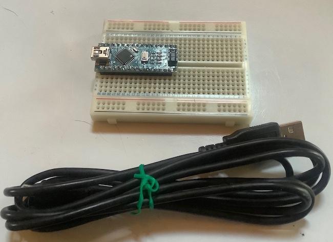
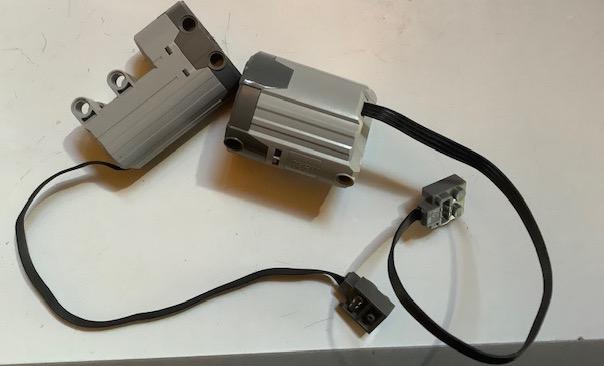
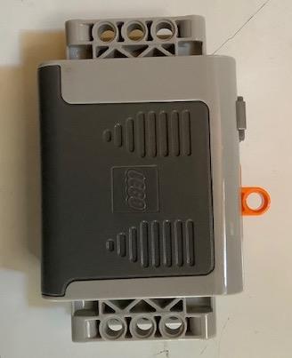
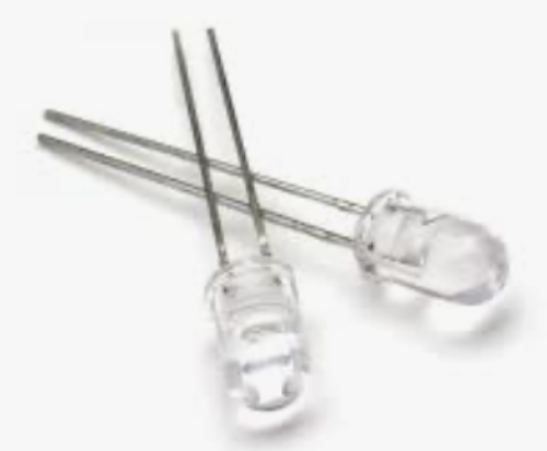
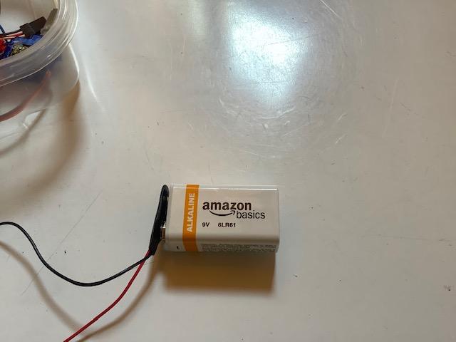
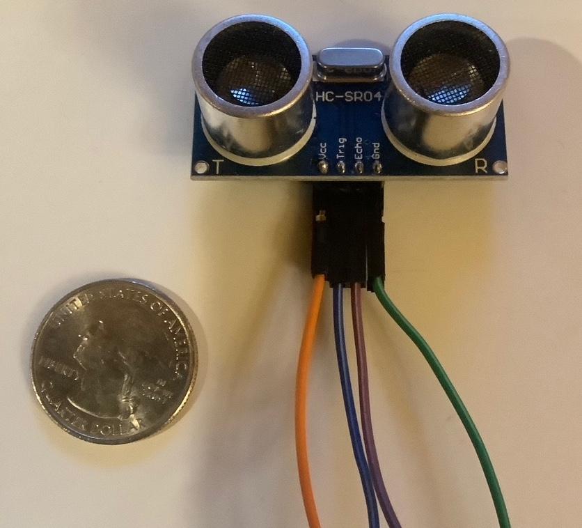
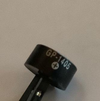
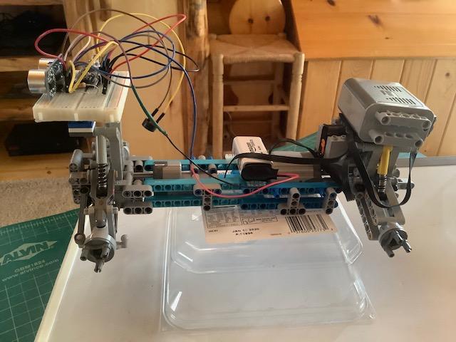
This self-driving car is made out of legos along with an Arduino Nano for control of a lego extra large motor for power, a lego servo motor for steering, a HC-SR04 (sonar sensor) for feedback, a piezo buzzer for sound, a lego remote control receiver, and an Infrared transmitter to control power and steering.
Downloads
Supplies
Electronics:
- Breadboard
- Arduino Nano
- USB cable
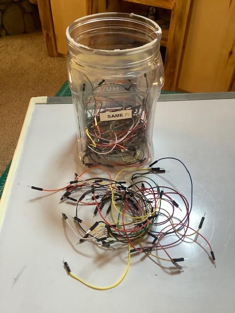
- Jumper Wires (30)
- Lego servo motor
- Lego extra large motor
- Lego remote control receiver
- Lego battery
- Infrared transmitter
- 330 ohm resistor
- 9-volt battery with wire connection
- Sonar Sensor HC-SR04
- Piezo Buzzer
Miscellaneous:
- Velcro
- Scissors for cutting velcro
Legos:
- See attached list
Software
- Arduino
Setting Up Hardware
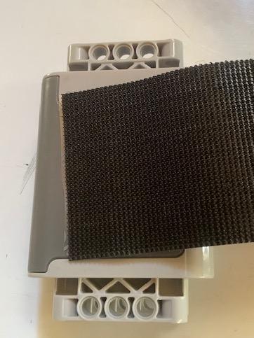
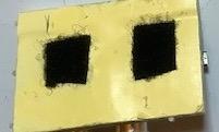
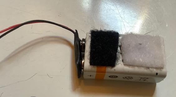
Secure all items listed under supplies.
Attach velcro to the following items:
- Lego Battery- attach velcro to a wide edge
- Breadboard attach velcro to the bottom
- 9-volt battery - attach velcro to a wide edge
Setting Up Software
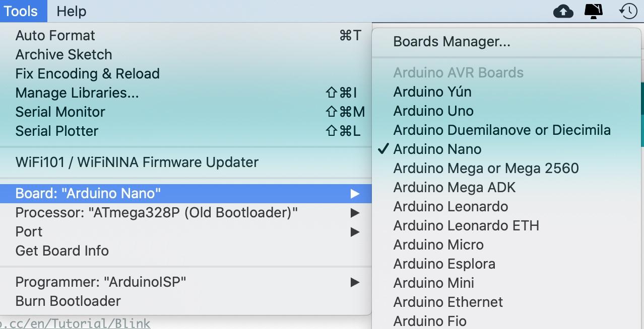
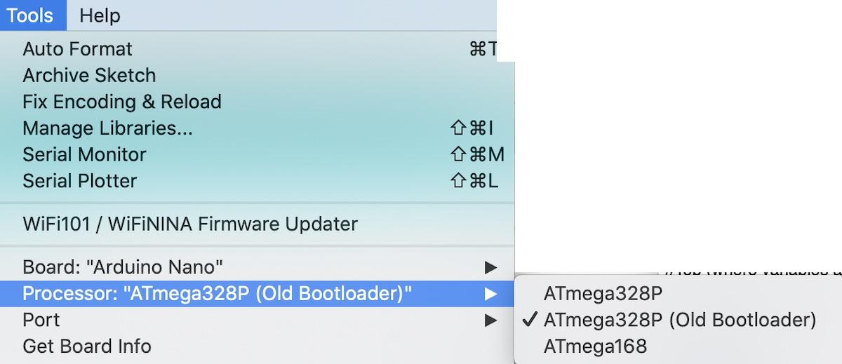
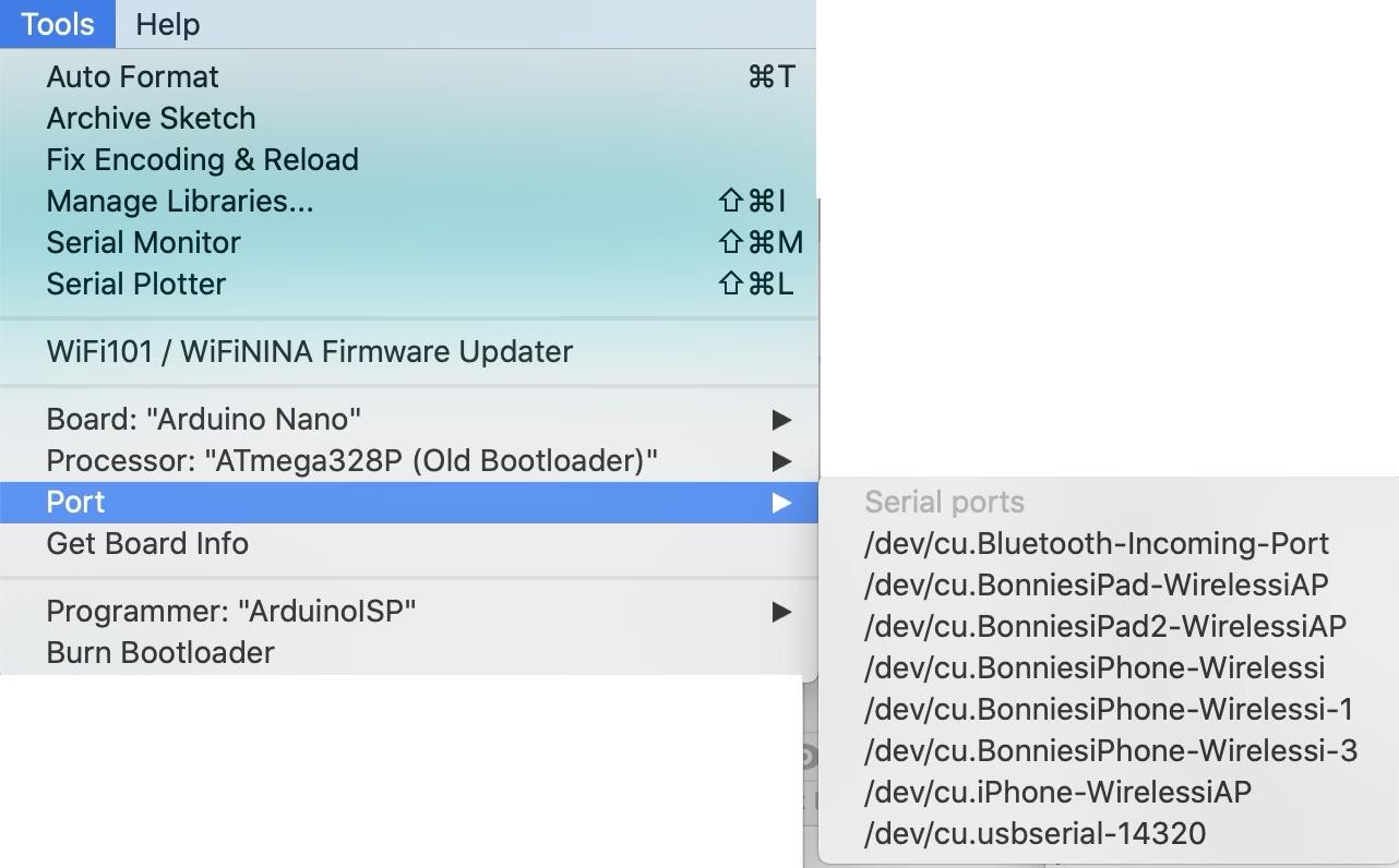
1) Download the Arduino software from https://www.arduino.cc/en/Main/Software.
Note: It is free - donation is optional.
2) Follow the directions to install the software for your system.
3) Open the Arduino software.
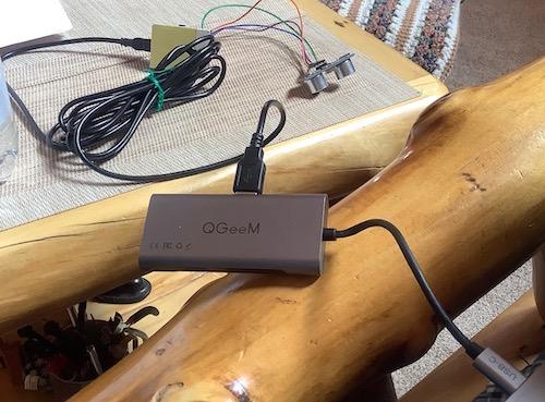
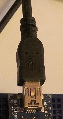
4) Plug the small end of the cord into the Arduino and the USB end into your computer (see photos 1 and 2).
Note: My set up may look a little different from your set up. My MacBook only has USB-C ports so I have to go through a USB hub.
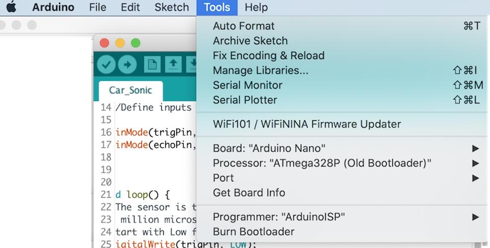
5) Select the Nano Board under Tools — there are many different Arduino boards (see photo 3).
6) Select the Processor under Tools - when I purchased the Arduino nano it said to use this one see photo 4).
7) Select the Port - /dev/cu.usbserial-14320 (see photo 5)
Note: If the option is slightly different (like different numbers on the end) that should work.
Tip: Always check these three settings when you connect your nano and open the Arduino Software.
Test Software
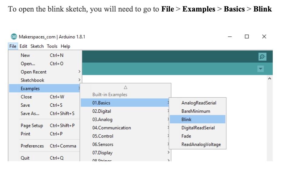


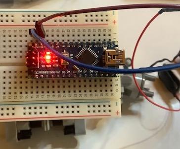
In this step, we will run one of the sample Arduino programs.
1) Connect the Arduino to your computer. Check the port, processor, and type of Arduino selected as noted in the previous step.
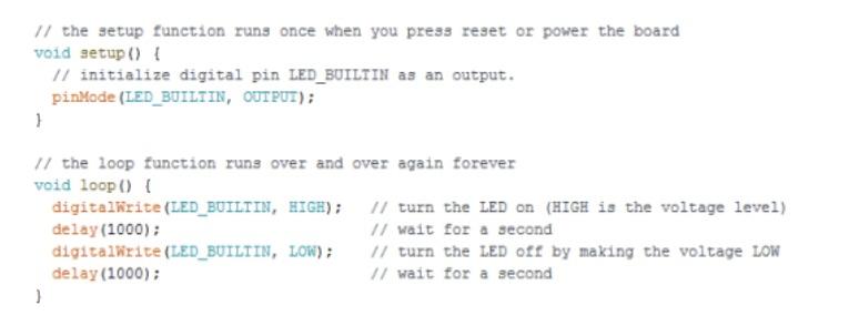
2) Open the example Blink (photo 1).
3) The code is shown in photo 2. Every Arduino sketch (program) has two main parts:
void setup() - sets things up that have to be done once and then don’t happen again.
void loop() - contains the instructions that get repeated over and over until the board is turned off.
Notes:
Anything following // are simply notes - the computer, when running the program, ignores these.
Under void setup() - the { } are important - they define what is included in setup.
pinMode(LED_BUILTIN, OUTPUT);
// every Arduino includes a builtin in light called LED_BUILTIN. Output declares this pin as an output.The semicolon at the end of each line is required.
Under void loop() - the { } are important - they define what is included in the loop.
digitalWrite(LED_BUILTIN,HIGH);
digtalWrite(LED_BUILTIN, LOW);
// digitalWrite is a command that tells the Arduino to send a message to a pin // the message is typically HIGH or LOW - in this case HIGH means the light turns on and LOW means off delay(1000).
//delay is a command that tells the program to pause (so the light stays on or off).
//the number in () tells how long to pause in milliseconds.
//1000 milliseconds is 1 second.
4) Running the code requires two steps:
Step 1 - Verify the code - click the checkmark (see photo 3).
Step 2 - Upload the program to the Arduino Nano (see photo 4).
5) Look at the Arduino - is the light blinking?
If not, press reset button (it is in the center of the board - labelled reset).
6) So far we have been running the Arduino from computer power. However, once the Arduino is programmed (program is uploaded), it can run off battery power.
Step 1 - Disconnect the Arduino from the cord connected to your computer.
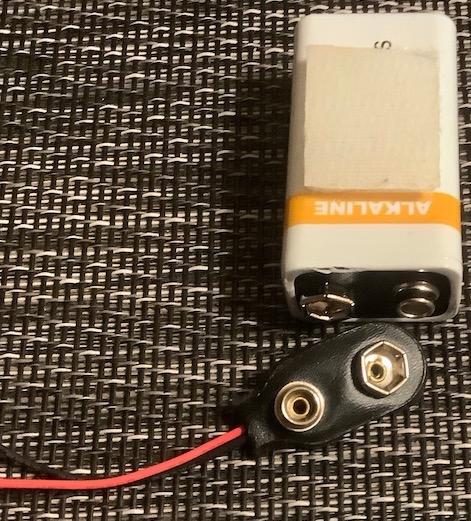
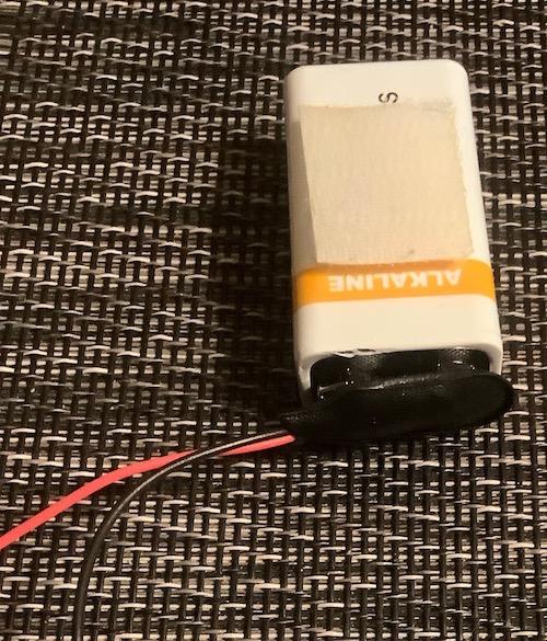
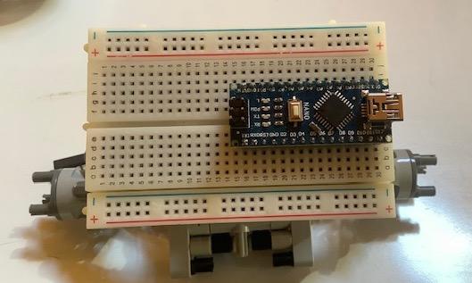
Step 2 - Connect the 9 volt battery to the battery holder (see photos 5 and 6) and insert the wires in the breadboard to connect them to the Arduino board (GND and VIN as noted in photos 7 and 8).
Note: Do not let the wires touch each other.
7) Look at the Arduino - is the light blinking?
If not, press the reset button (it is in the center of the board - labelled reset).
Building the Lego Car: Rear Section
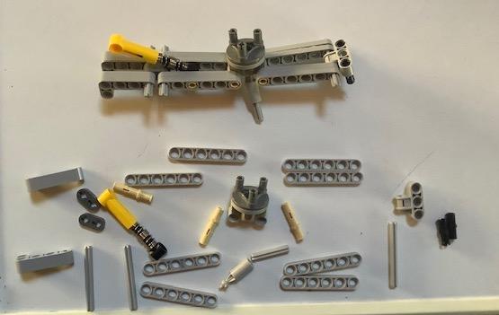
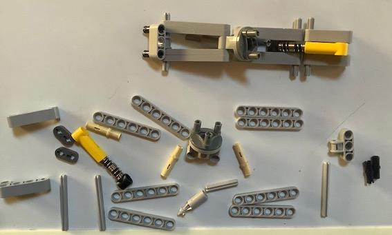
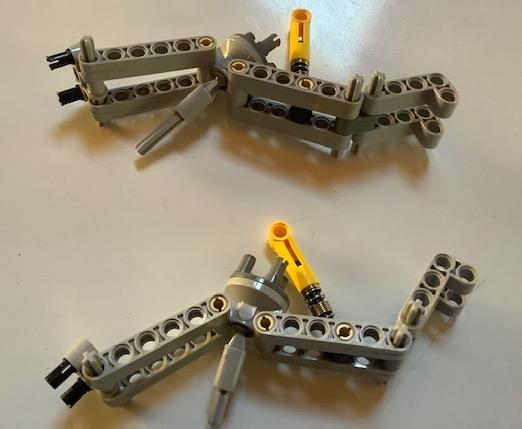
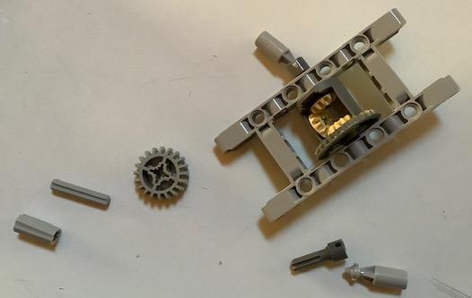
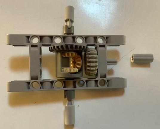
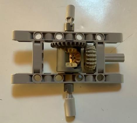

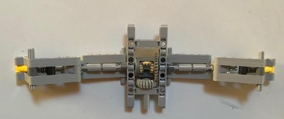
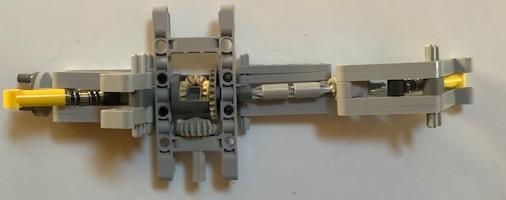
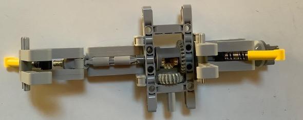
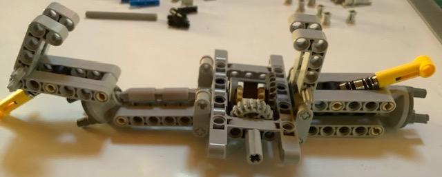
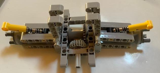
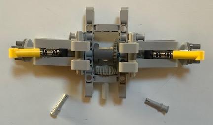
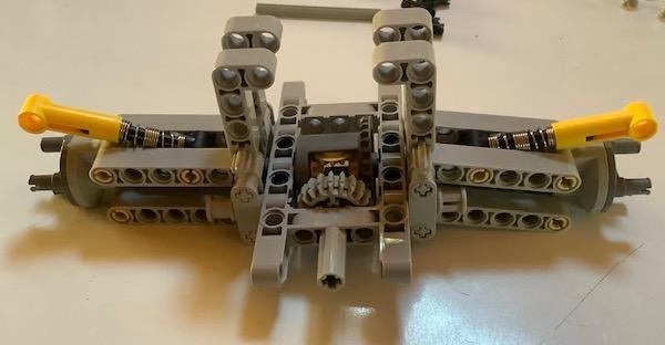
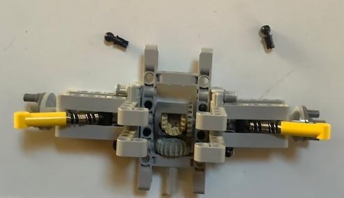
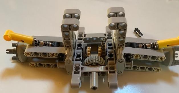
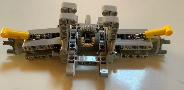
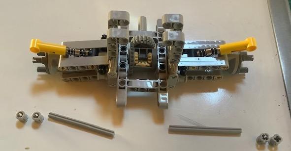
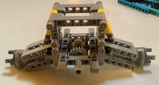
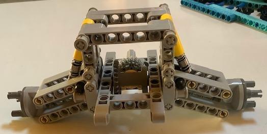
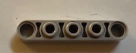
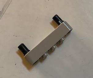
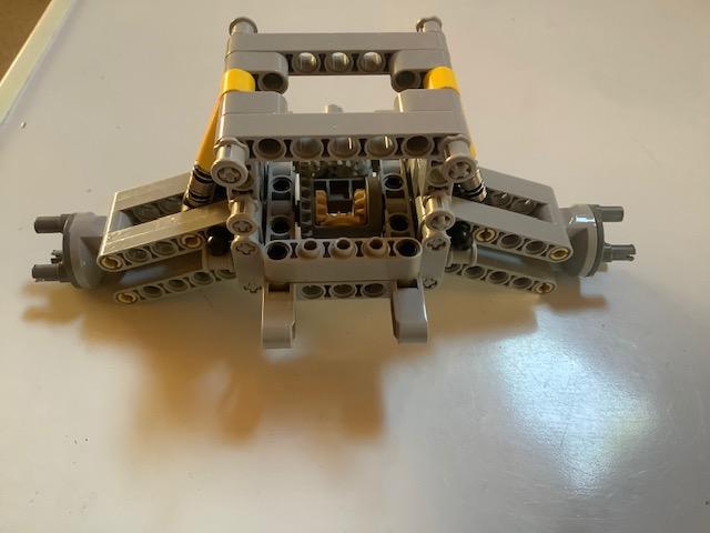
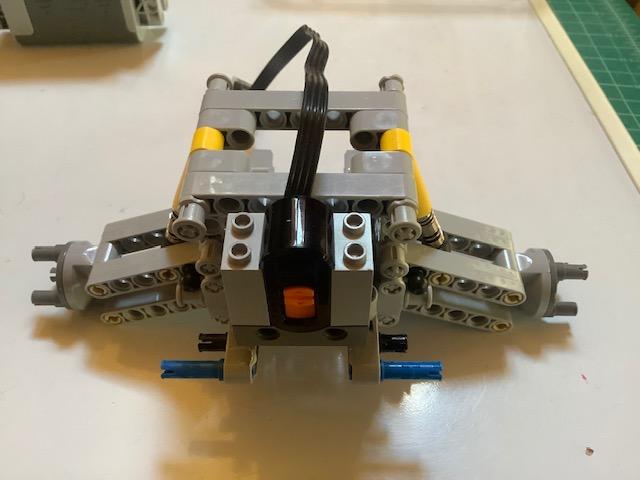
In steps 4 (rear), 5 (front), and 6 (body) we will build the lego car. It is a simple variation of the lego 42037 car. Purchasing lego 42037 along with a few extra plates and beams (see complete list under parts) would be the easiest route. If you choose to purchase 42037 - the tires and wheels from that set will definitely work instead of the tires/wheels which I choose. All parts also are available from Bricklink and other third party stores. Follow the photos in order to build the car.
Building the Lego Car: Front Section
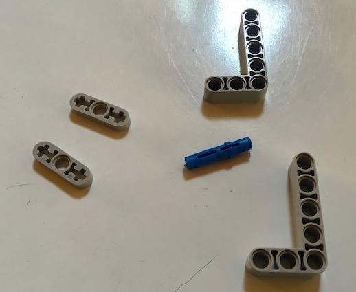
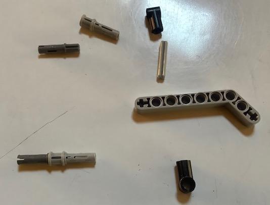
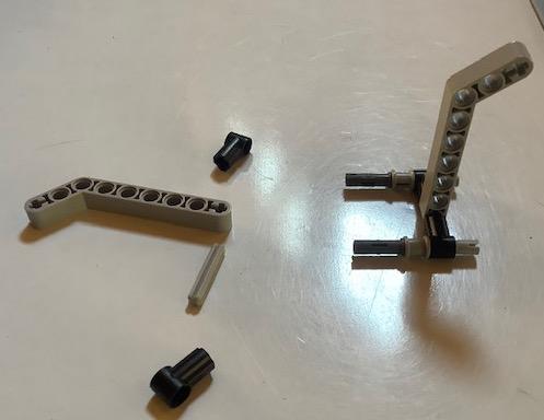
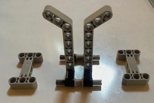
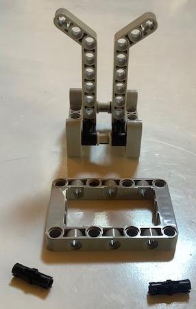
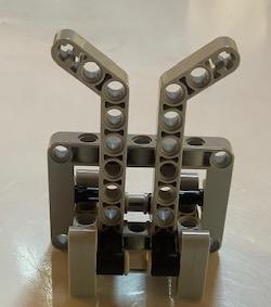
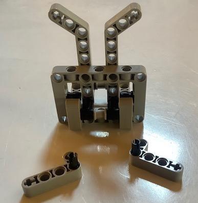
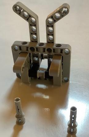
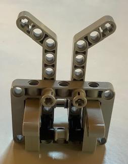
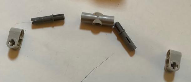
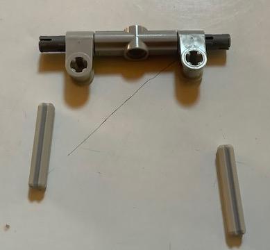
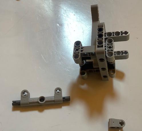
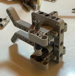
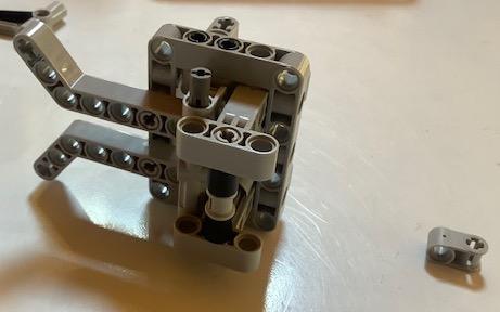
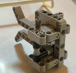
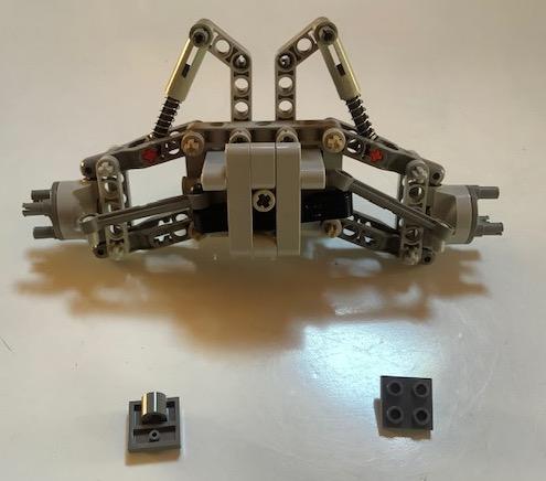
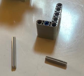
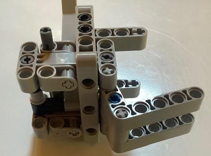
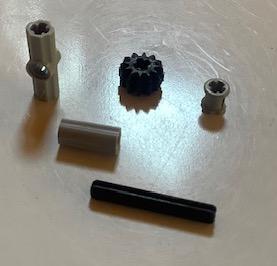
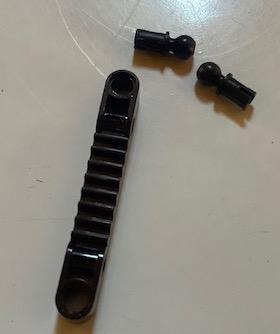
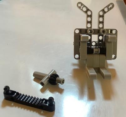
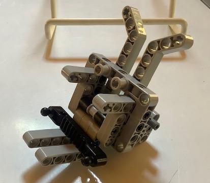
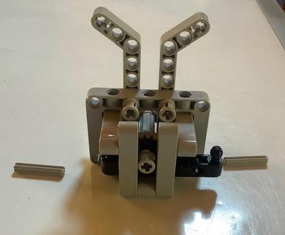
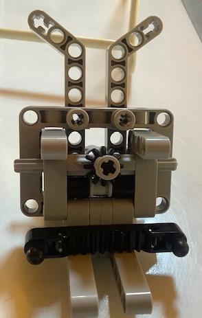
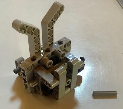
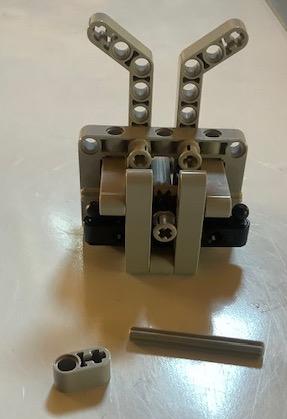
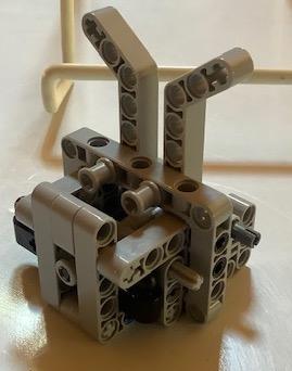
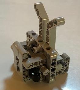
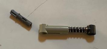
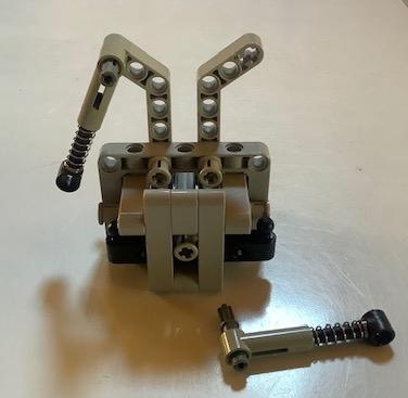
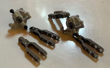
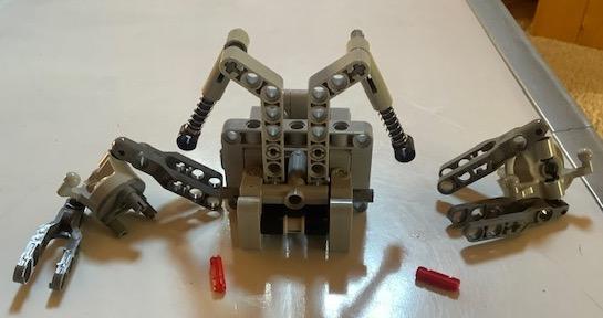
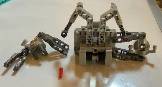
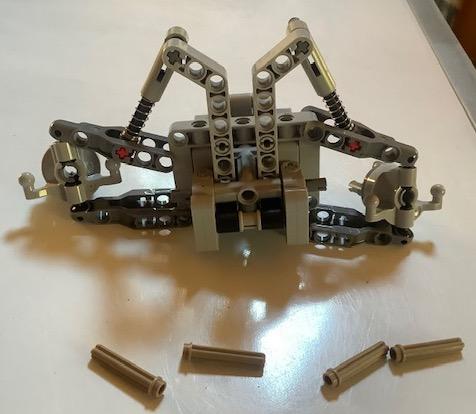
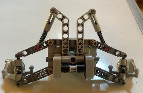
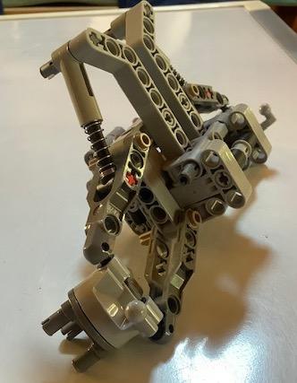
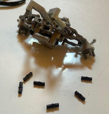
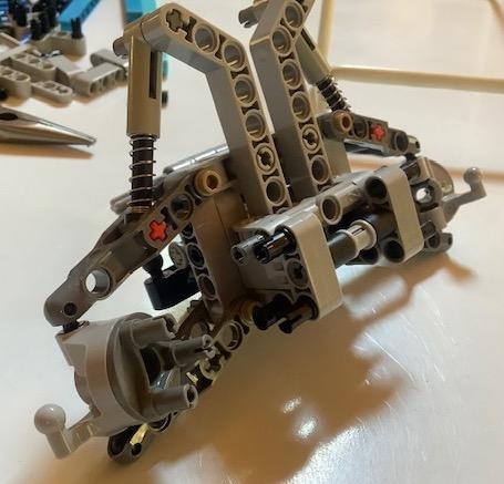
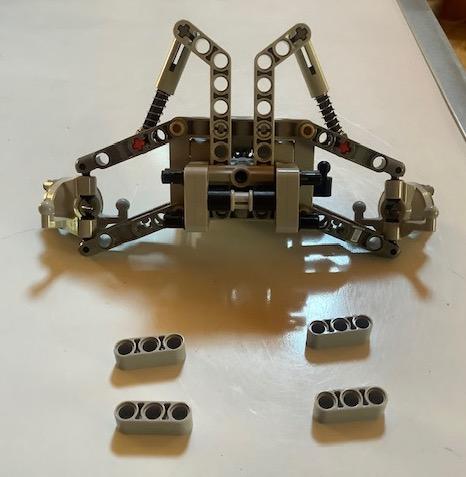
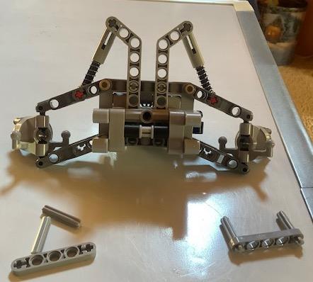
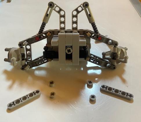
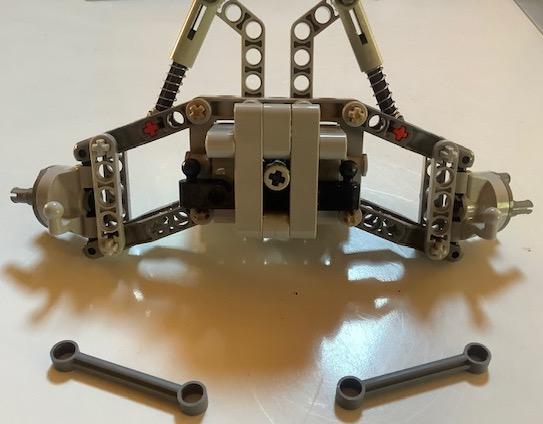
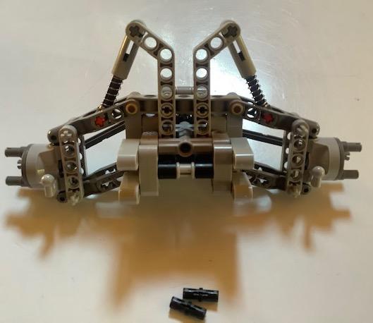
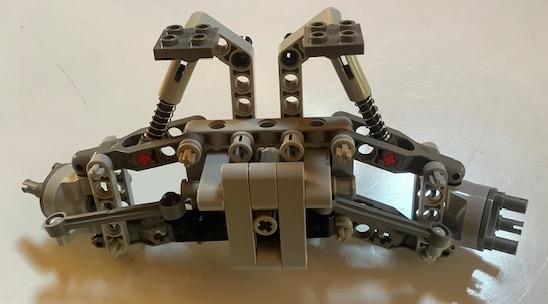
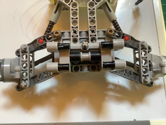
Follow the photos in order to build the front section of the car.
Building the Lego Car: Center Body Section
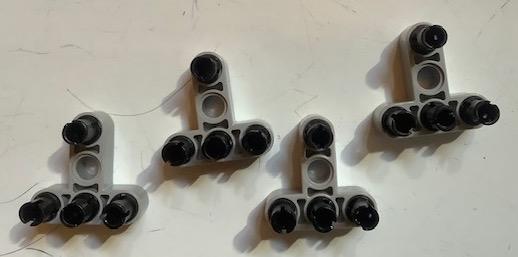

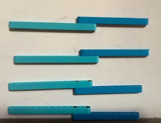
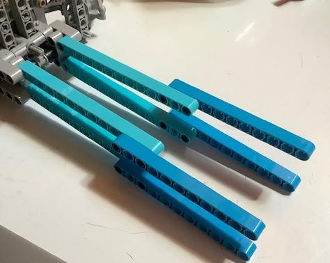
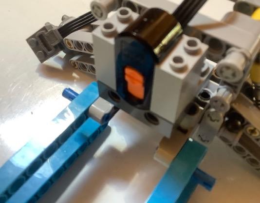
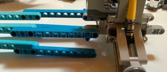
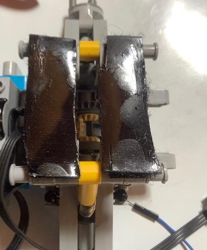
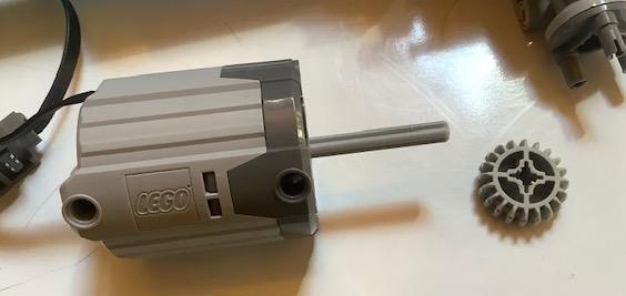
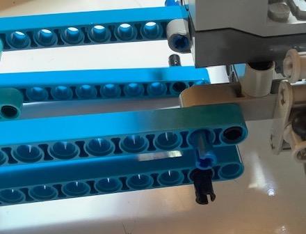
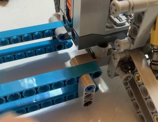
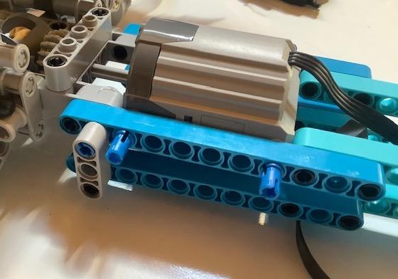
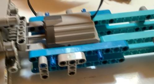
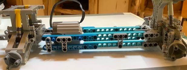
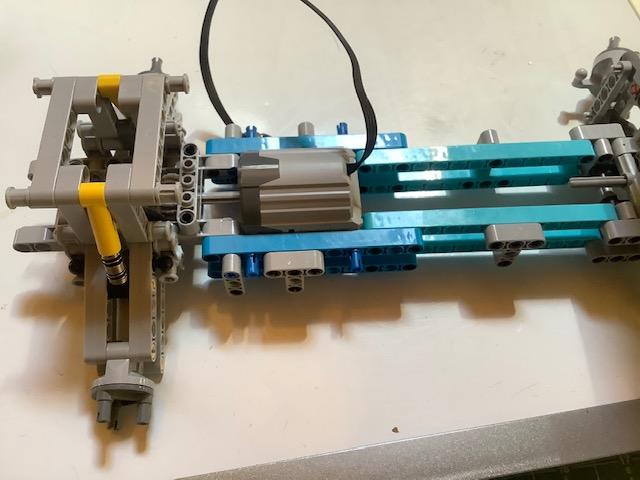
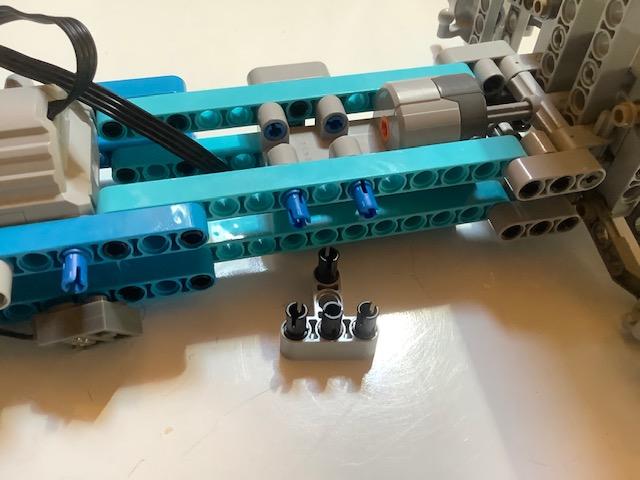
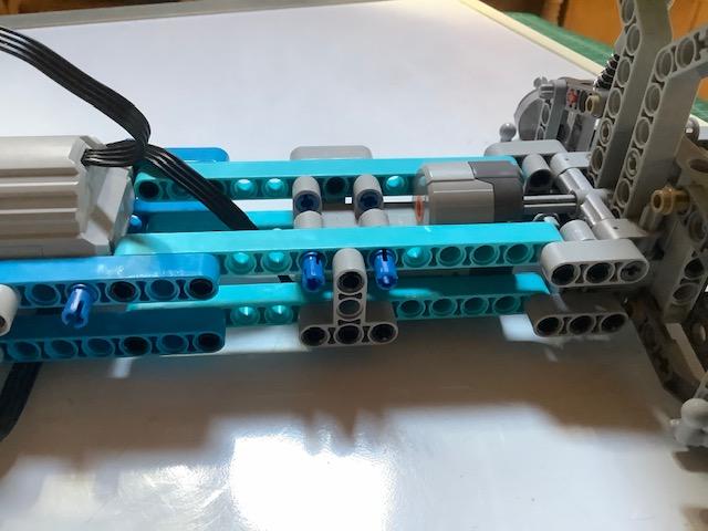
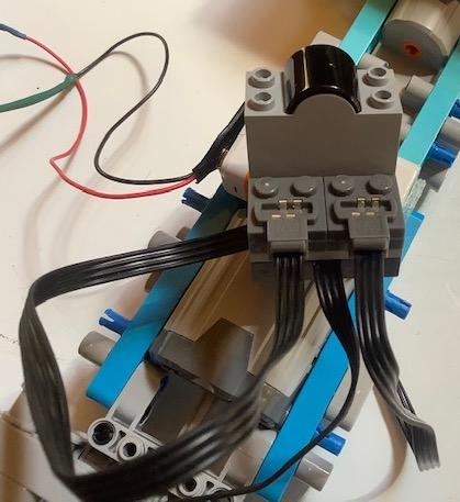
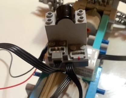
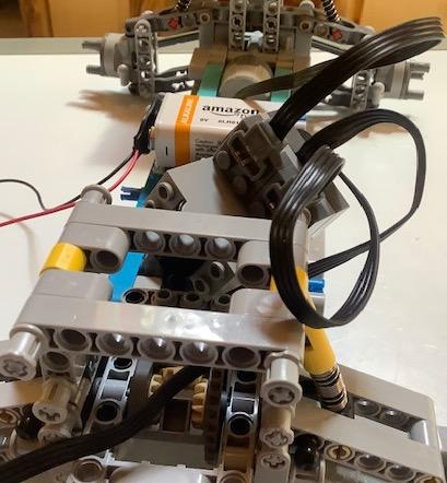
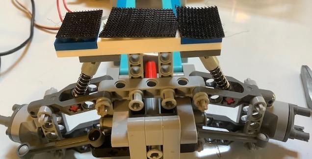
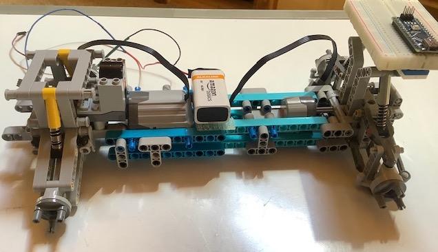
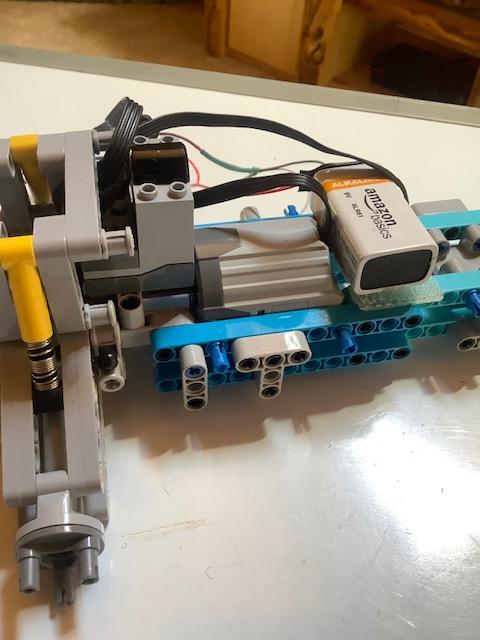
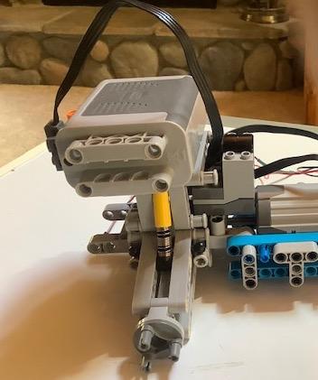
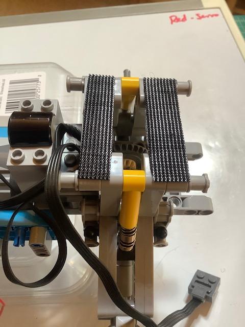
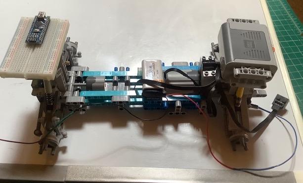
Follow the photos in order to build the center body section of the car.
Adding Sonic Sensor
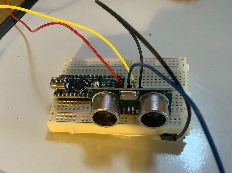
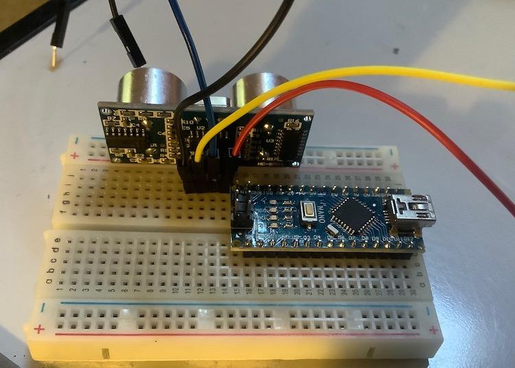
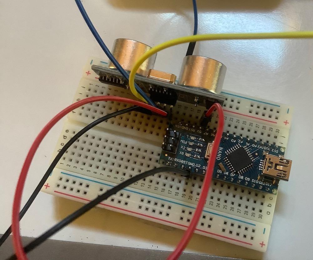
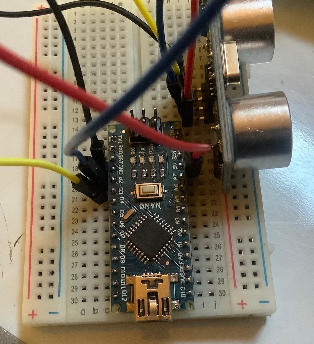
Now we will start setting up the self driving part of the car. In this step we will set up and program the ultrasonic sensor (part HC-SR04). It is often advisable to set up and test one item at a time, so that you have fewer problems when you put it all together.
Hardware Set Up
1) Insert the ultrasonic sensor pins (4) in column J - rows 11, 12, 13, and 14 of the breadboard (photos 1 and 2).
Note: Make sure the HC-SR04 is facing out from the board.
2) Use four wires to connect Arduino to the ultrasonic sensor (photo 3 and 4).
Red wire - Sonic VCC to Arduino 5V.
Black wire - Sonic Gnd to Arduino Gnd.
Blue wire - Sonic trig pin to Arduino D2.
Yellow wire - Sonic echo pin to Arduino D3.
Software Set Up
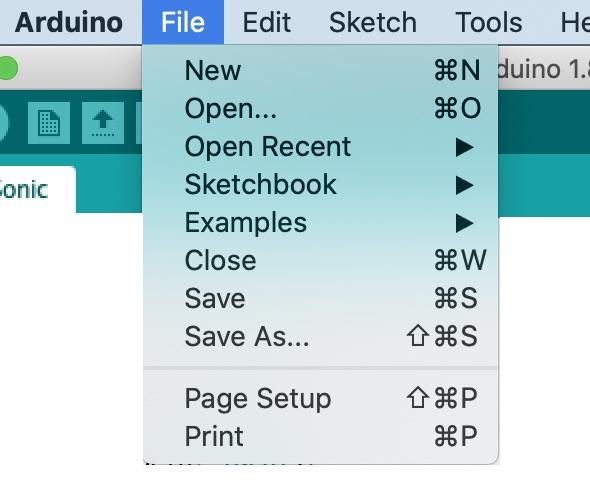
1) Download Car_Sonic.ino code for testing the sonic sensor (item 5).
2) Select File/Open to open Car_Sonic.ino code. (photo 6).
Here is the program without the comments (the part the computer program reads):
int lastTurn = 0;
long duration;
long distance;
const int trigPin = 2;
const int echoPin = 3;
void setup() {
Serial.begin(9600);
pinMode(trigPin, OUTPUT);
pinMode(echoPin, INPUT);
}
void loop() {
digitalWrite(trigPin, LOW);
delayMicroseconds(5);
digitalWrite(trigPin, HIGH);
delayMicroseconds(12);
digitalWrite(trigPin, LOW);
duration = pulseIn(echoPin, HIGH);
distance = (duration/2) *0.0135;
Serial.print(distance);
Serial.print(" in ");
Serial.println();
delay(1000);
}
Note: Be sure to read the comments in the actual code. The variable int lastTurn will keep track of the direction in which the car last turned as we add the servo motor in the next step.
Hardware/Software Check
1) Attach the Arduino to your computer.
2) Check the Board, Processor, and Port - same settings as in previous step.
3) Verify the sketch (checkmark).
4) Download the sketch to the Arduino Nano.
5) Select Tools / Serial Monitor (photo 7).
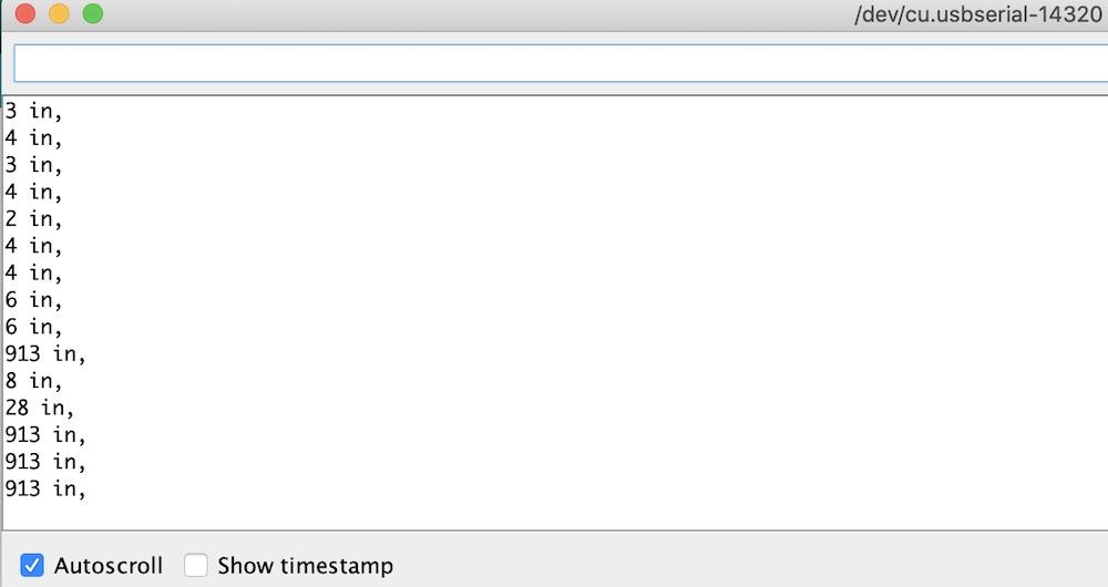
6) Move a book in front of the sensor - vary the distance and watch the output on the screen (photo 8).
Note: If you get a really big number, the sound wave may be bouncing off something outside.
Downloads
Adding Servo Motor and Infrared Transmitter for Steering
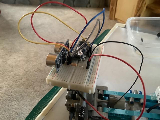
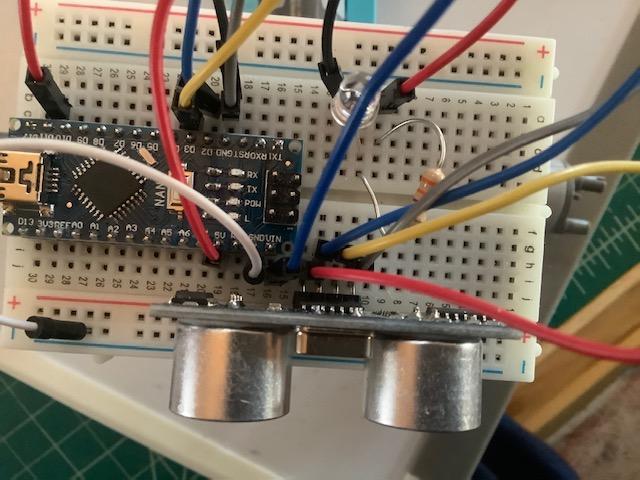
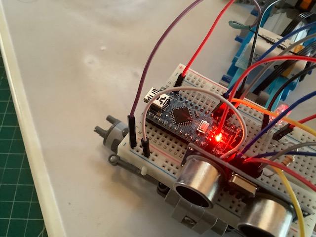


In this step we will set up and connect an infrared transmitter to the lego servo, so that the Arduino may control the car’s steering. Servo motors when powered only make a half circle (180 degrees) turns.
Hardware Set Up:
1. Connect infrared transmitter (photo 1) to Arduino
Insert short wire in row 12 column b
Insert long wire in row 11 column d
Insert resistor in row 11 column e and row 10 column c
Insert wire in row 10 column a and connect to port D11
2. Connection of 9 volt battery (photos 2 and 3) to Arduino
Connect wire from port Gnd to Gnd rail.
Connect positive (blue in photo) to port Vin.
Connect negative (dark red in photo) to negative rail when you want to power the Arduino.
3. Ensure that the lego servo is connected to the red port on the lego receiver and that the lego receiver is connected to the battery.
Software Set Up:
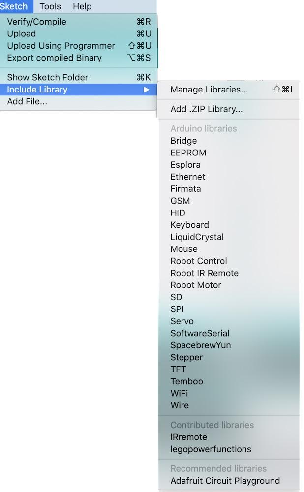
The Arduino program (by itself) does not have support for the Lego Power Functions. However, someone has written a piece of code to add this function to the Arduino. Pieces of code like this are called libraries and they have an extension of .h In order to use a library you have to add it to your version of Arduino:
- Download LEGOPowerFunctions.zip from http://basbase.com/robocam/LEGOPowerFunctions.zip (photo 4)
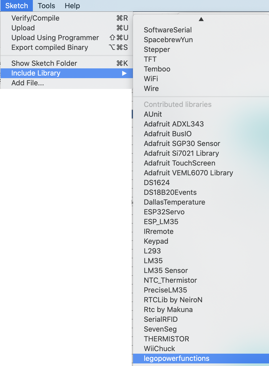
- Select Sketch - Include Library - Add .zip Library (photo 5)
- Select LEGOPowerFunctions.zip (photo 6)
- Check that legopowerfunctions has been included in your software (photo 7)
- Download ServoPFTrans.ino (item 8)
Here is the sketch (without comments) for the testing the servo (turn right, turn center, turn left). We will use most of this code in the self driving car sketch. Be sure to read through the comments in the actual program.
#include
LEGOPowerFunctions lego(11);
void setup() {
}
void loop() {
lego.SingleOutput(0, PWM_FWD4, RED, CH1);
delay(2000);
lego.SingleOutput(0, PWM_FLT, RED, CH1); //Return to center
delay(2000);
lego.SingleOutput(0, PWM_REV4, RED, CH1);
delay(2000);
}
Note: The basic control for controlling lego motors is
lego.SingleOutput(0, direction/distance, connection color, channel on Lego Receiver)
PWM_FWD4 - turns the servo motor completely in one direction
PWM_REV4 - turns the servo motor completely in the opposite direction
PWM_FLT - turns the servo motor to 90 degree or neutral position
Hardware/Software Check
1. Check the Board, Processor, and Port - selections should be the same as in the last step.
2. Verify the sketch (checkmark).
3. Place the car on an elevated surface so the wheels can turn easily.
4. Download the ServoPFTrans.ino to the Arduino Nano
5. Connect the negative wire from the 9 volt battery to the negative rail on the breadboard after disconnecting the USB cord.
6. Watch the car.
It turns right and holds for two seconds.
It centers and holds for two seconds.
It turns left and holds for two seconds.
Note: This repeats forever or until you unplug the Arduino from your computer.
Downloads
Including Lego Extra Large Motor for Power
The lego extra large motor controls moving the car. Lego motors (other than the servo motor), when powered, rotate in a continuous circle (360 degrees clockwise or counter clockwise).
In this step we will set up and connect the infrared transmitter to the lego extra large motor, so that the Arduino may control the car’s movement.
Hardware Set Up:
1. The infraRed transmitter used in the previous step also can control the extra large motor.
2. Ensure that the lego extra large motor is connected to the blue port on the lego receiver and that the lego receiver is connected to the battery.
Software Set Up:
The lego power functions library was added in the previous step.
- Download DCPFMotorTrans.ino (figure 1)
Here is the sketch (without comments) for the testing the extra large motor (forward, stop, backward). We will use most of this code in the self driving car sketch. Be sure to read through the comments in the actual program.
#include
LEGOPowerFunctions lego(11);
void setup() {
}
void loop() {
lego.SingleOutput(0, PWM_FWD4, BLUE, CH1); //Forward
delay(2000); //equals 2 seconds
lego.SingleOutput(0, PWM_BRK, BLUE, CH1); //Stop
delay(2000);
lego.SingleOutput(0, PWM_REV4, BLUE, CH1); //Backward
delay(2000);
lego.SingleOutput(0, PWM_BRK, BLUE, CH1); //Stop delay(2000);
}
Note: The basic control for controlling lego motors is
lego.SingleOutput(0, direction/distance, connection color, CH1)
PWM_FWD4 - turns the motor completely in one direction at a high speed
FWD1, FWD2, FWD3 are slower speeds
PWM_REV4 - turns the motor completely in the opposite direction at a high speed
REV1, REV2, REV3 are slower speeds
PWM_BRK - stops the motor
Hardware/Software Check
1. Check the Board, Processor, and Port - selections should be the same as in the last step.
2. Verify the sketch (checkmark).
3. Place the car on an elevated surface so the wheels can turn easily.
4. Download the DCPFMotorTrans.ino to the Arduino Nano
5. Connect the negative wire from the 9 volt battery to the negative rail on the breadboard after disconnecting the USB cord.
6. Watch the car:
Moves forward for two seconds
Stops for two seconds
Reverses for two seconds
Stops for two seconds
Note: This repeats forever or until you unplug the Arduino from your computer.
Downloads
Adding Piezo for Sound
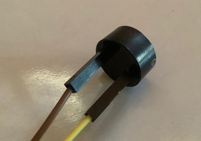
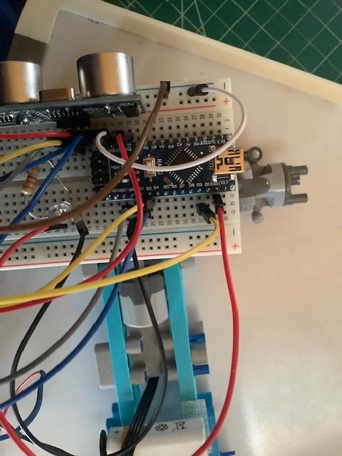
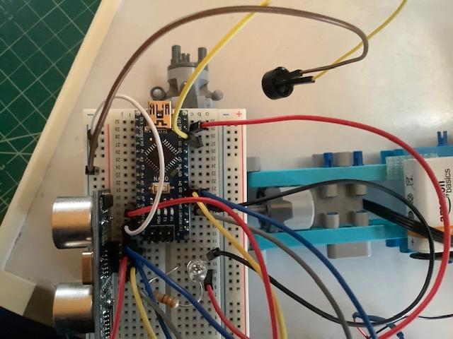
The piezo buzzer makes sounds that may be controlled by the Arduino.
Hardware Set Up
The piezo buzzer has two wires (yellow and dark purple in the photo (see photo 1). One wire is connected to the positive side (marked by a "+" symbol and the other is connected to the negative side).
1. Attach the negative (dark purple) wire to the negative rail on the breadboard (see photos 2 and 3)
2. Attach the positive (yellow) wire to D9 (see photos 2 and 3)
Software Set Up
1. Download the Car_Sound.ino (item 4).
Here is the sketch (without comments) for the testing the sound. We will use most of this code in the self driving car sketch. Be sure to read through the comments in the actual program.
const int buzzerPin = 9;
void setup() {
pinMode(buzzerPin, OUTPUT);
}
void loop() {
tone(buzzerPin, 262, 1000);
delay(2000);
}
Note: The tone command functions as follows
tone(arduino pin, frequency, duration)
For example, tone(buzzerPin, 262, 1000) plays the C note for 1000 milliseconds
Note: The Arduino's tone() command will play notes of a given frequency.
note frequency note frequency
c 262 Hz d 294 Hz
e 330 Hz f 349 Hz
g 392 Hz a 440 Hz
b 494 Hz. C 523 Hz
Hardware/Software Check
1. Verify the sketch (checkmark).
2. Check the Board, Processor, and Port - selections should be the same as in the last step.
3. Download the Car_Sound.ino to the Arduino Nano
4. Connect the negative wire from the 9 volt battery to the negative rail on the breadboard after disconnecting the USB cord.
5. Listen for the sound.
Note: This repeats forever or until you unplug the Arduino from your computer.
Downloads
Self Driving Code
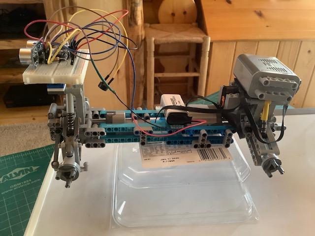
Now it is time to observe the car responding to external stimuli (objects in front of the sonar device)
Hardware Set Up
The hardware was set up in the previous steps.
Software Set Up
Download SelfDriveCarPF.ino (item 1)
Most of the code for this sketch is from the previous steps. The new pieces include three main if/then statements as well as one if/then/else statement. The logic is as follows:
Find out how far the car is from an obstacle - use Solar Sensor
if very close (less than 12 inches) then stop car, reverse for 1 second
if close (farther than 12 inches but less than 18 inches) then stop
if very close or close (less than 18 inches) then turn opposite direction of last turn and go
Here is the sketch (without comments) for the testing the car.
#include
int lastTurn = 0;
long duration;
long distance;
const int trigPin = 2;
const int echoPin = 3;
const int buzzerPin = 9;
LEGOPowerFunctions lego(11);
void setup() {
Serial.begin (9600);
pinMode(trigPin, OUTPUT);
pinMode(buzzerPin, OUTPUT);
pinMode(echoPin, INPUT);
}
void loop() {
lego.SingleOutput(0, PWM_FWD5, BLUE, CH1);
digitalWrite(trigPin, LOW);
delayMicroseconds(5);
digitalWrite(trigPin, HIGH);
delayMicroseconds(10); /
digitalWrite(trigPin, LOW);
duration = pulseIn(echoPin, HIGH);
distance = (duration/2) * 0.0135;
Serial.print(duration);
Serial.println();
Serial.print(distance);
Serial.print(" in ");
Serial.println();
if(distance < 12) {
Serial.print("<12");
Serial.println();
lego.SingleOutput(0, PWM_BRK, BLUE, CH1);
delay(1000);
lego.SingleOutput(0, PWM_REV4, BLUE, CH1);
tone(buzzerPin, 262, 1000);
delay(1000);
}
if(distance >= 12 & distance < 18) {
Serial.print("12-18");
Serial.println();
lego.SingleOutput(0, PWM_FLT, BLUE, CH1);
delay(1000);
}
if (distance < 18) {
Serial.print("<18");
Serial.println();
if(lastTurn==0) {
Serial.print("Turn 0");
Serial.println();
lego.SingleOutput(0, PWM_FWD7, RED, CH1);
delay(15);
lego.SingleOutput(0, PWM_FWD2, BLUE, CH1);
delay(2000);
lego.SingleOutput(0, PWM_FLT, RED, CH1);
lastTurn = 1;
}
else {
Serial.print("Turn 1");
Serial.println();
lego.SingleOutput(0, PWM_REV7, RED, CH1);
delay(15);
lego.SingleOutput(0, PWM_FWD2, BLUE, CH1);
delay(2000);
lego.SingleOutput(0, PWM_FLT, RED, CH1);
lastTurn = 0;
}
}
}
Hardware/Software Check
1. Elevate the car (see photo 2)
2. Verify the sketch (checkmark).
3. Check the Board, Processor, and Port - selections should be the same as in the last step.
4. Download the SelfDriveCarPF.ino to the Arduino Nano
5. Keep the USB cable attached and open the Serial Monitor (under Tools)
6. Move an object (like a book) in front of the sonic sensor and watch the car react by moving forward and backward, stopping, and turning directions.
Note: This repeats forever or until you unplug the Arduino from your computer.
Downloads
Test! Test! Test!
It is very important to test and then test again.
Download the FinalSelfDriveCarPF.ino
The code is the same as Step 11 but without any writing to the Serial Monitor.
Download the FinalSelfDriveCarPF.ino to the Arduino Nano
Remove the USB cable and plug in the negative wire from the 9volt battery and turn on the lego battery
Put the car in different situations on the floor and just sit back and watch.
Correct the code as needed - change delays, distance responses, speeds, turns.
Servo Motor
PWM_FWD - turns the motor to the right (1-7 determines how far it turns)
PWM_REV - turns the motor to the left (1-7 determines how far it turns)
PWM_FLT - returns to center
Power Motor (Medium, Large, Extra Large)
PWM_FWD - turns the motor clockwise to move the car forward (1-7 determines the speed)
PWM_REV - turns the motor counter-clockwise to move the car backward (1-7 determines the speed)
PWM_FLT - slows dow the motor gradually
PWM_BRK - stops the motor
Trouble Uploading the Program
- Make sure you have selected Arduino Nano from Tools->Board
- Make sure you have selected the correct Port and Processor
Trouble with the Program Running
- Double check all wires to make sure they are in the correct location.
- Make sure the infrared transmitter has a clear line of sight to the lego remote control receiver.