Lego Art Using Fusion 360
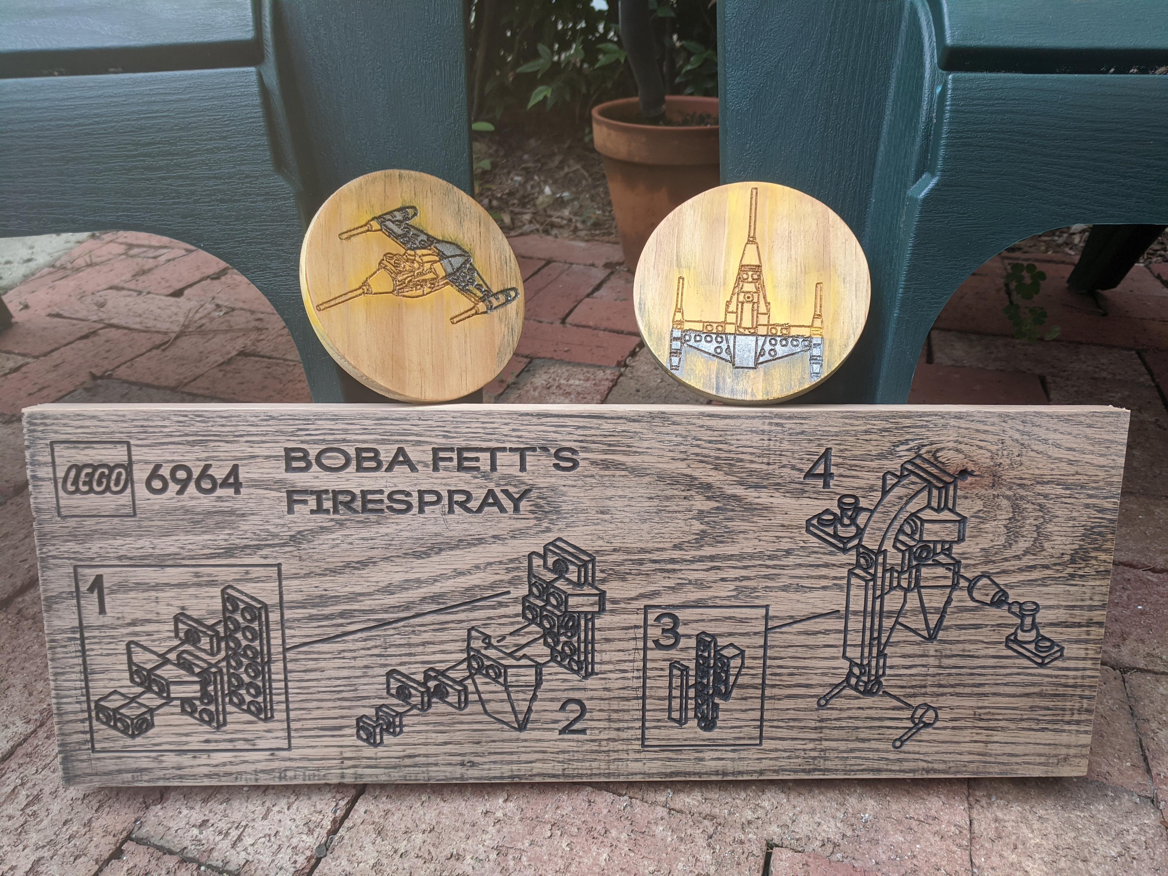
For this project, I decided to use Fusion 360's exploded view and drawing features to create 'assembly art'. Legos are in their best state when they are being assembled - when simple blocks begin to form more complex shapes and familiar profiles. Rather than just carve a Lego model, I wanted to capture Legos in their best state.
Supplies
To complete this project, you will need:
- A reasonably powerful PC or laptop running Fusion 360 and Inkscape
- A Lego set
- A pair of precision calipers
- Access to a CNC router and it's component software
- Wood, ideally hardwood like oak or walnut
- 220 & 400 grit sandpaper
- Tack cloth
- Black spray paint
Model Your Bricks
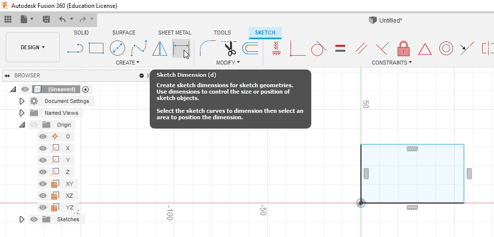
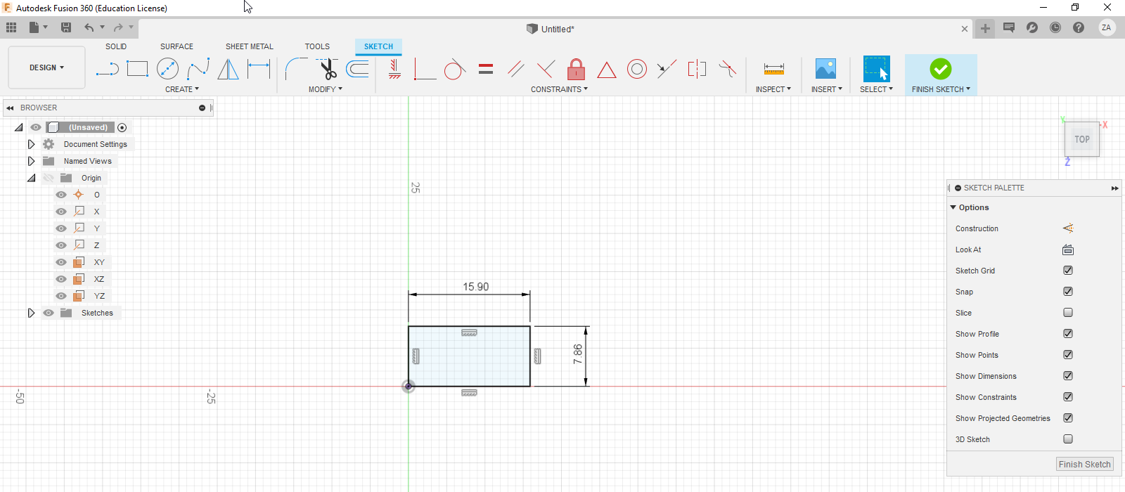
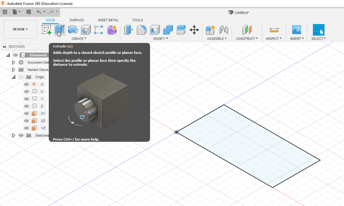
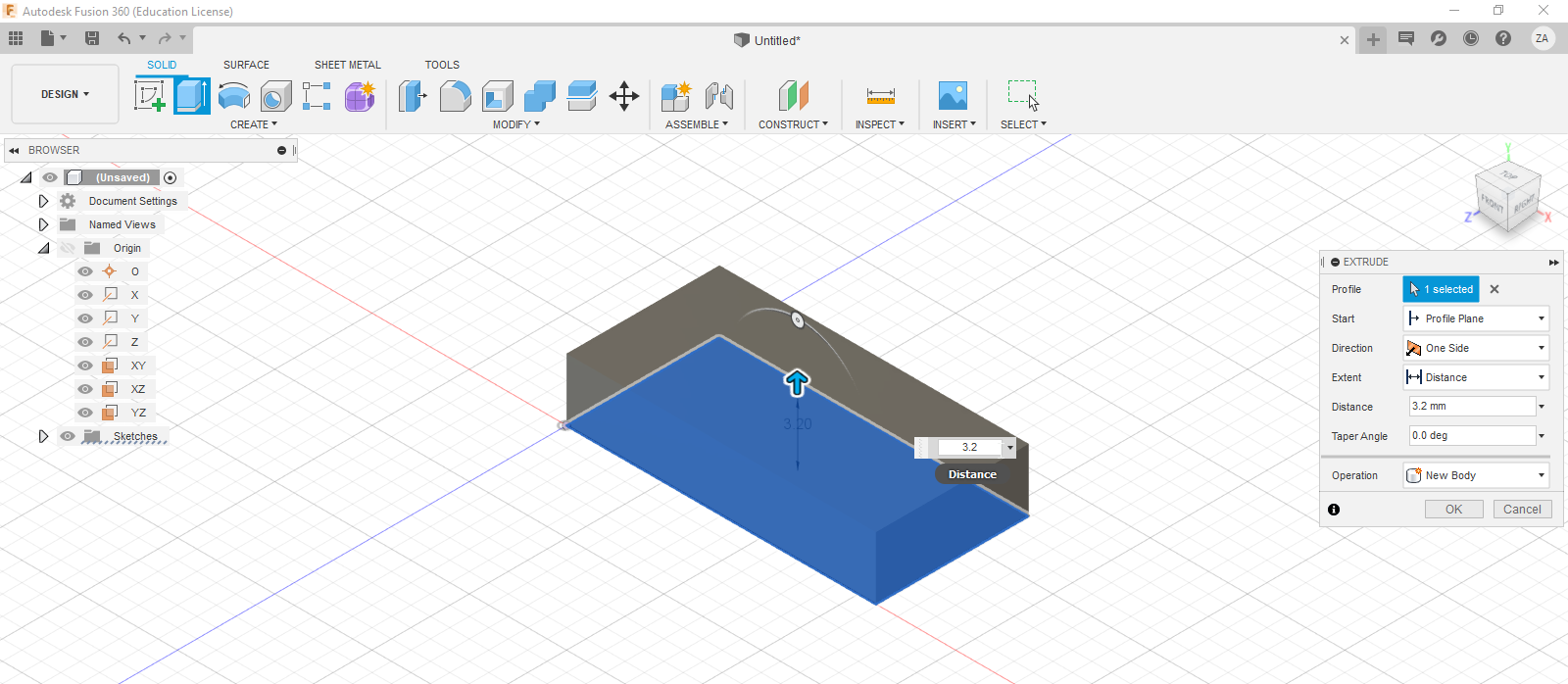
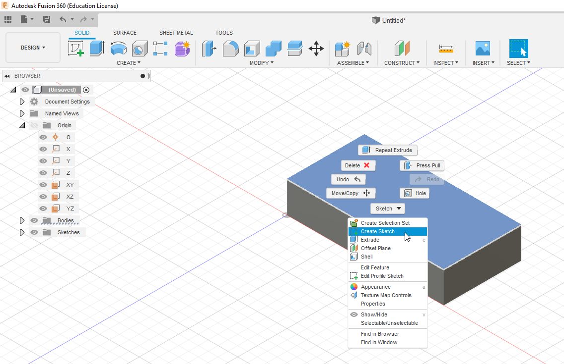
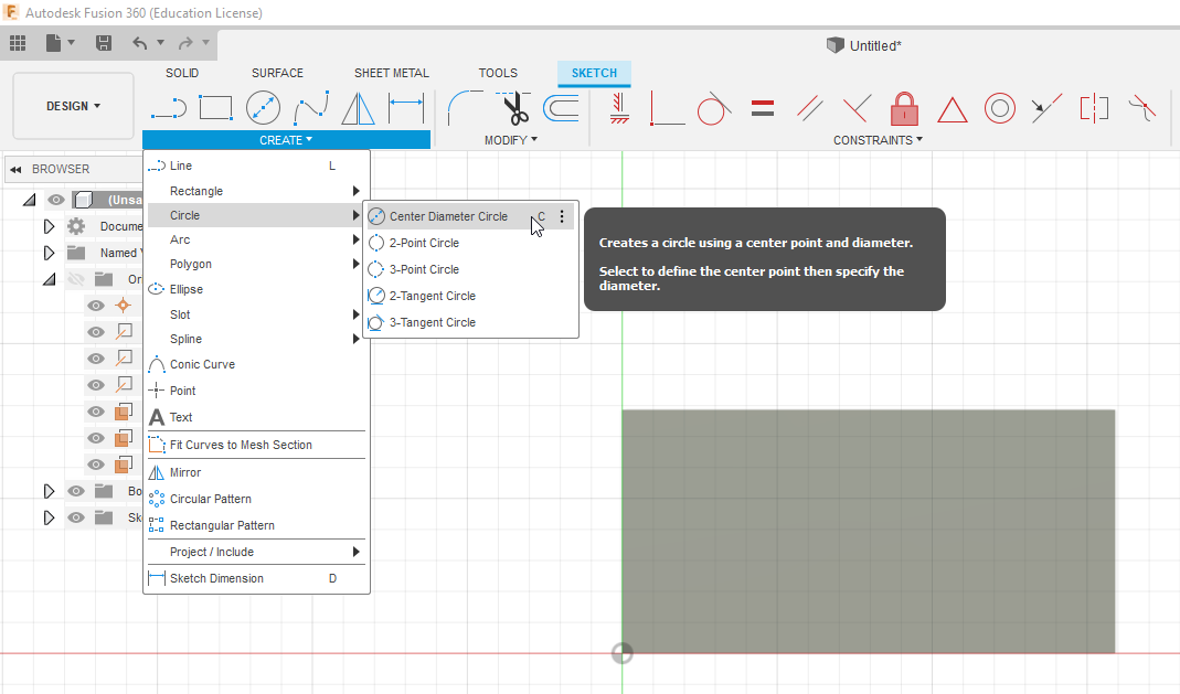
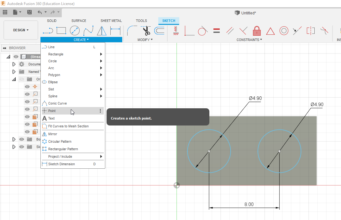

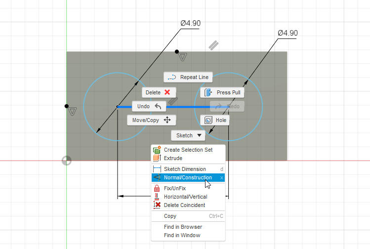
If you're new to 3D modeling, this is a great introductory project since Lego bricks are pretty easy to model and assemble. I'll go through the basic process for modeling simple parts. Key phrases are in bold - if you need more information, Googing these words will help. For more advanced parts, you may need to find a video explaining how to use certain features, like lofts.
Modeling a Flat 1x2 Brick
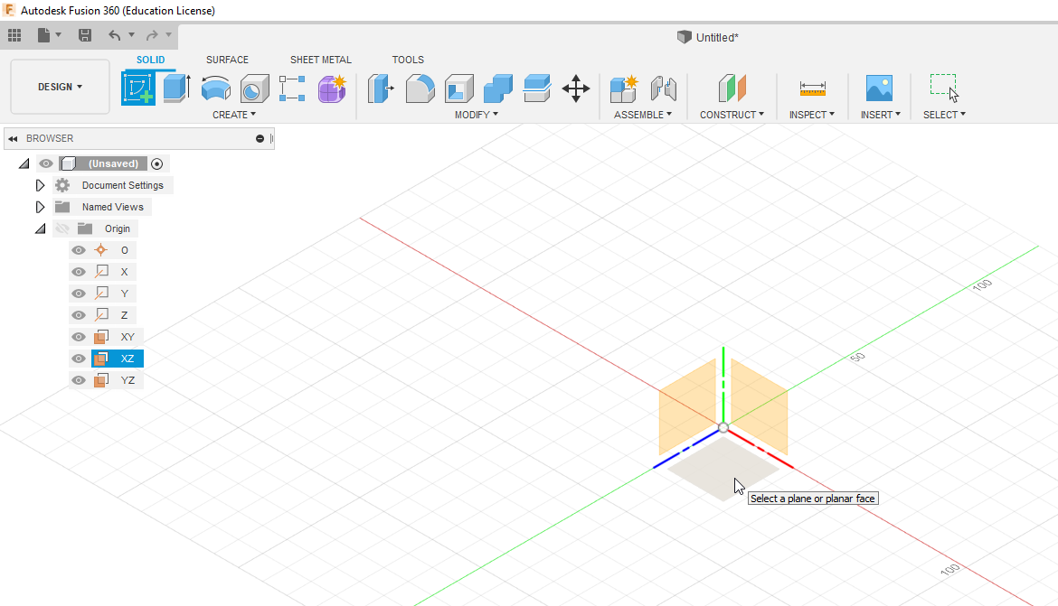
Step 1: Create a sketch and choose a plane
When creating 3D models, a sketch is usually your first step. In Fusion, when creating a sketch, you choose which plane to create it on. By default, you have 3 planes (xy, yz, xz) that create your basic views: Front (xy), Top (xz) and right (yz). For this part, select the xz plane.
Step 2: Create a box and dimension it
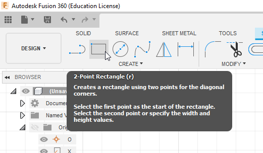
In order to correctly size your sketch, dimensions are used to constrain it - we'll talk more about these later. Using the box tool, create a simple box of any size. You have the option to specify box size when you create it, or you can use the dimension tool. Measure you bricks with your calipers - you will find the piece has a rounded length of 15.9 mm and a width of 7.8 mm. Since our corner was created at the origin, it is has enough constraints and ready for extrusion.
Step 3: Extrude your sketch
Extruding adds a third dimension to our 2D sketch, making it a 3D object. Use the extrude tool and select the sketch area you just created. On the right panel, in the 'distance' field, specify 3.2 mm.
Step 4: Create a sketch with constraints
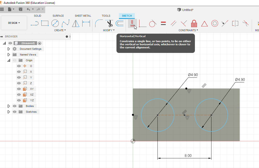
Next we're going to create the two top studs and practice using constraints. Click on the top of your new 3D box and create a new sketch. Use the circle tool to create two circles - both are 4.9 mm. The distance between the circles is 8 mm. Rather than place these circles using distance, we can reference other sketch elements, like the length and width of the square. To do this, create a point by clicking on 'create' < 'point'. If you hover around the middle of your lines, you'll notice a triangle appear, indicating you are hovering over the midpoint of the line. Click to place a line. Do this for your length and width lines.
Crate a line between the two circles by clicking 'create' < 'line'. Once placed, right click it and in the drop down menu, click 'normal/construction'. A construction line is used for constraining and does not affect your sketch. Create a point at the midpoint of this construction line.
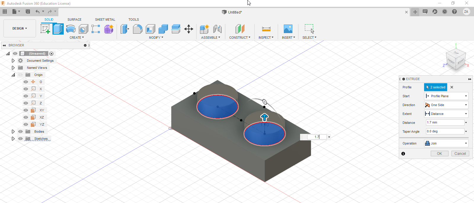
Finally, in the top menu in the constraints tab, click on horizontal/vertical. This constraint forces the selected points to become horizontal or vertical with one another, following all previous constraints, such as distance. Click on the length midpoint, then the construction line midpoint. Do the same for the vertical midpoint and your circle midpoint. Your sketch is now accurate. Extrude these studs by 1.7 mm.
Step 5: Use an offset to hollow out the bottom
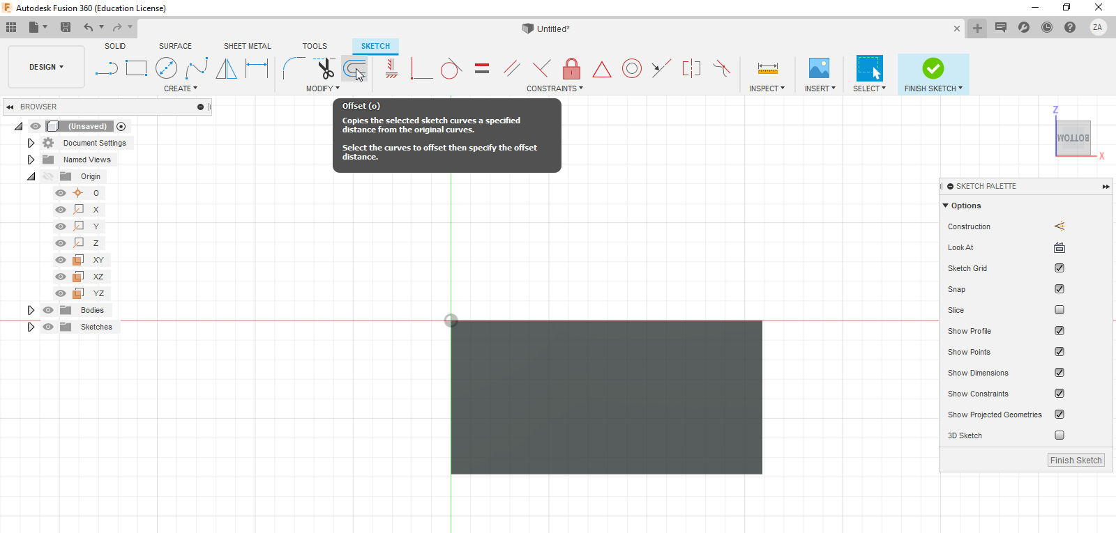
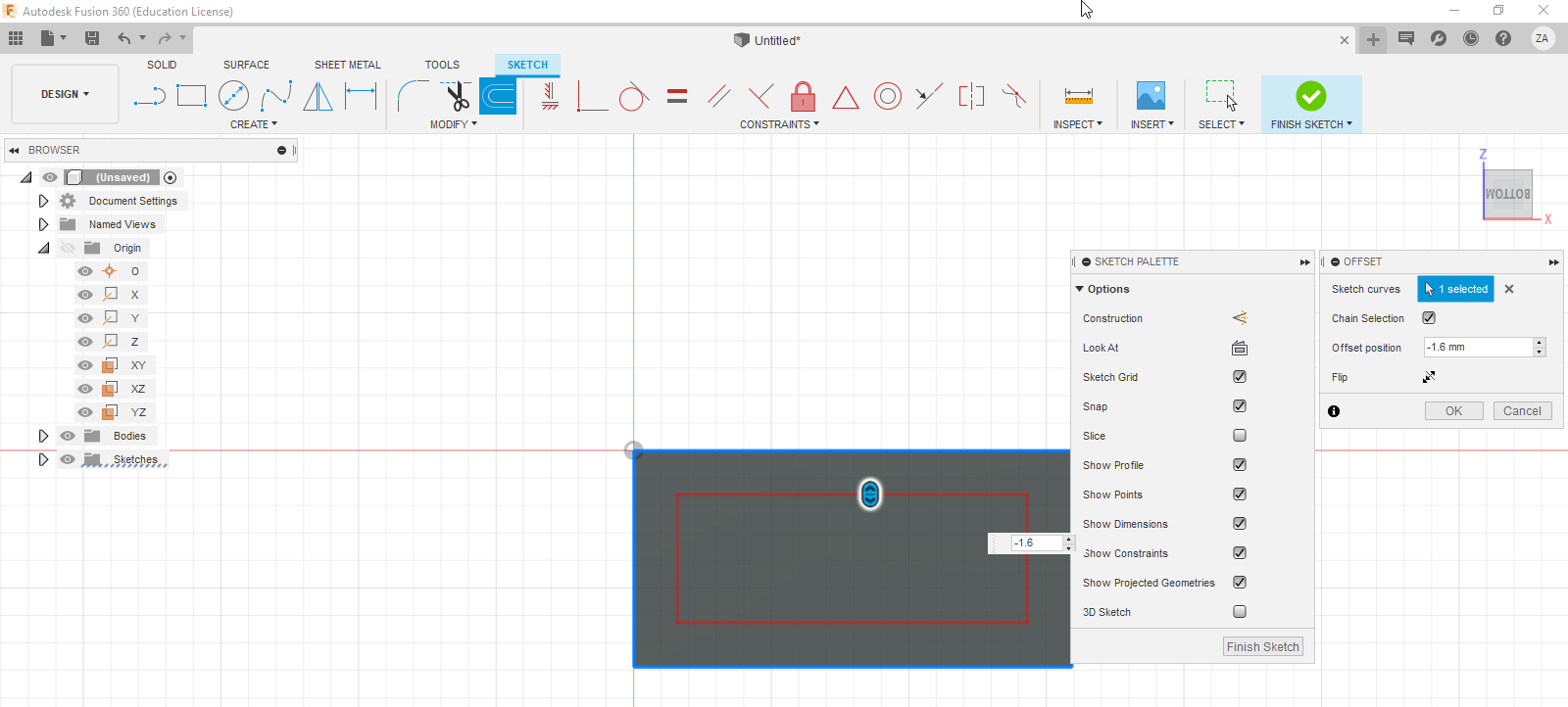
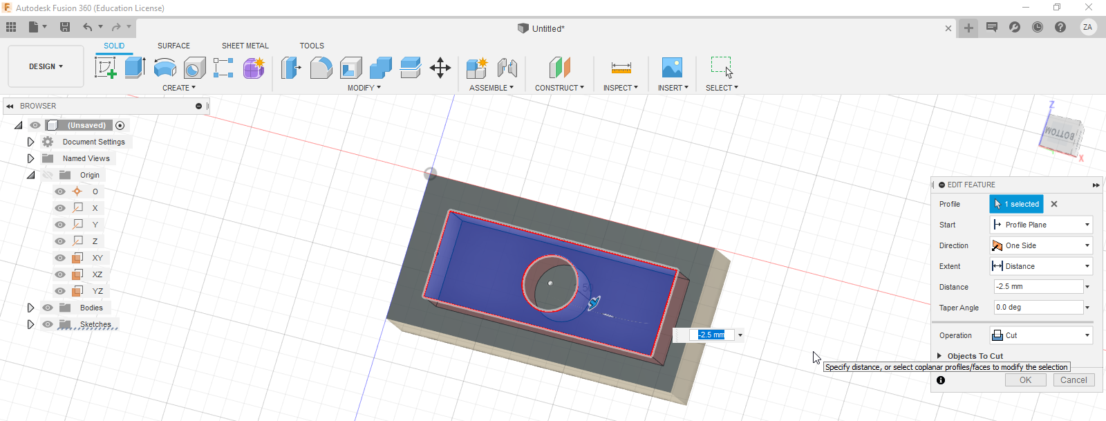
An offset takes a previous sketch and recreates it, uniformly larger or smaller based on your input. To do this, rotate your model and create a new sketch on the bottom of the brick. Click the 'offset' button, then click on the brick outline. Enter a value of -1.6 mm. The box is created with distance constraints so it is already fully defined.
Since the bottom of the brick has a center post, create a new circle with a diameter of 3 mm in the center. When you extrude, select the inner area without clicking on the center circle. Enter -2.5 mm, creating a cut that leaves the center post.
Step 6 (Optional): Final detail sketch
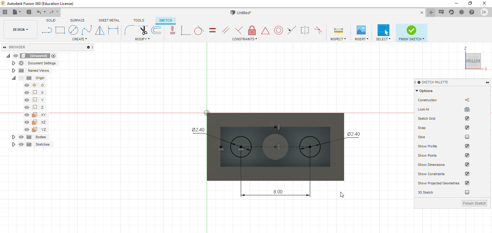
Practice step 4 on the small holes on the bottom of the brick. The holes are still 8 mm apart, but have a diameter of 2.4 mm. Make a cut of -2 mm.
Step 7: Save your work
Always remember to save your final work.
Build a Digital Lego Set!
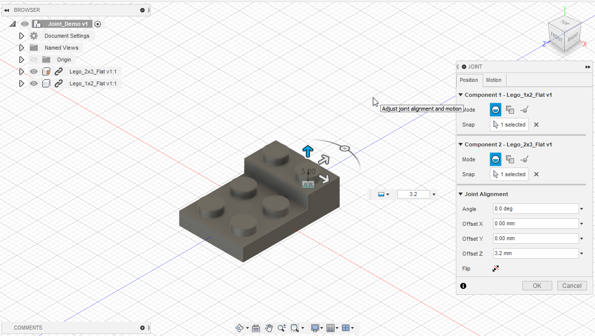
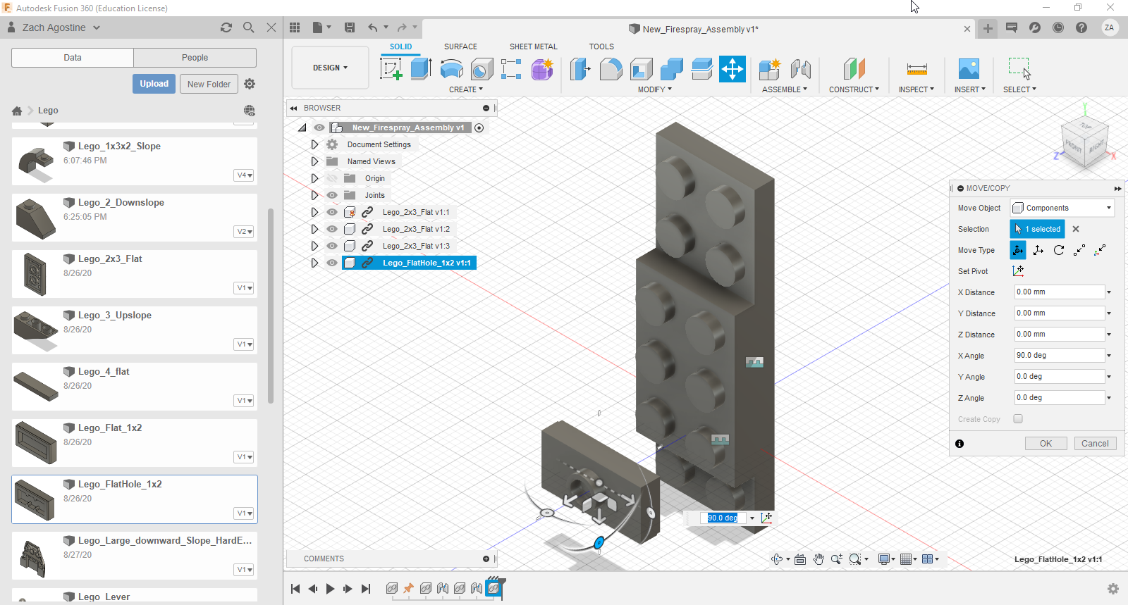
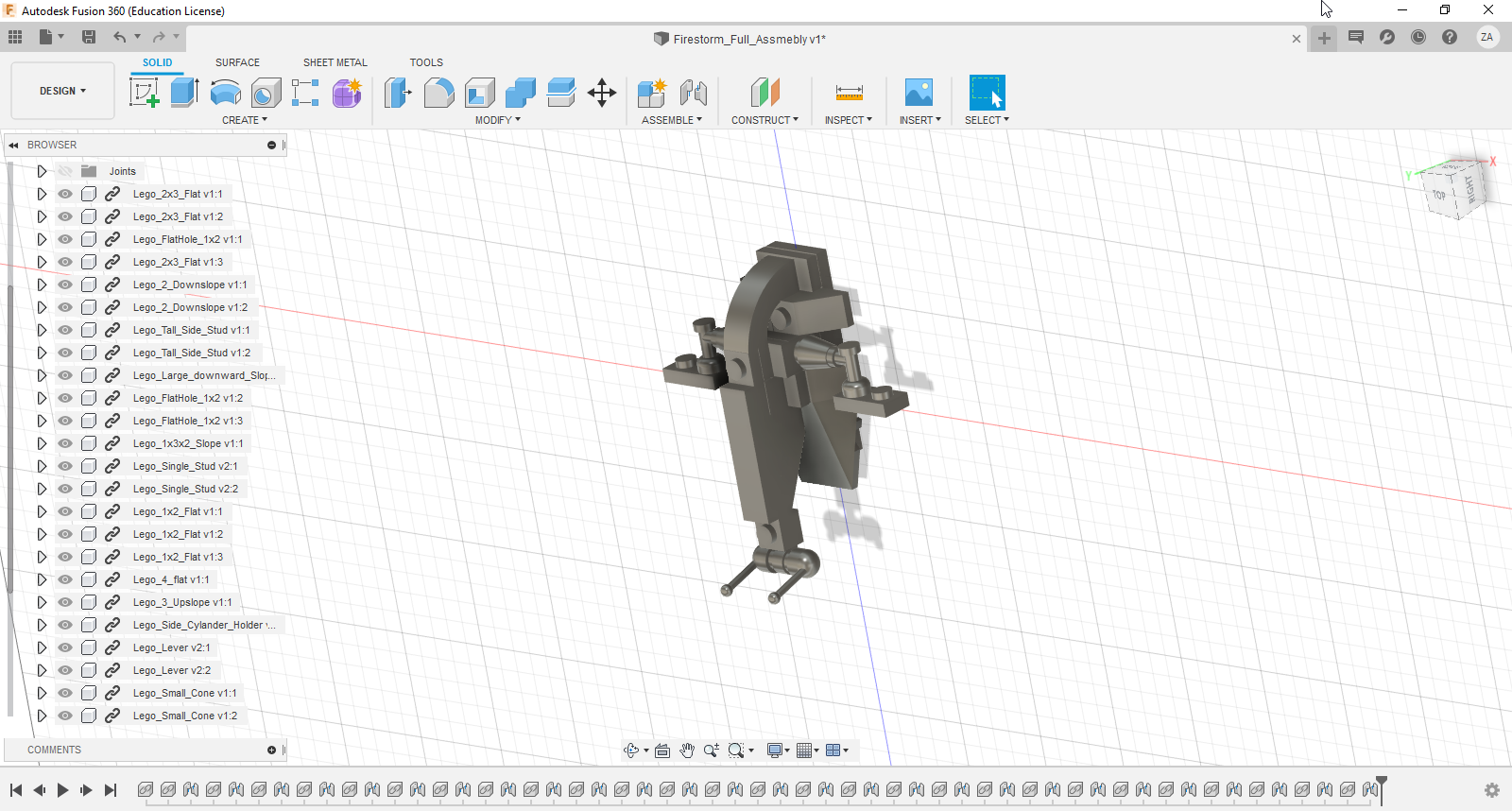
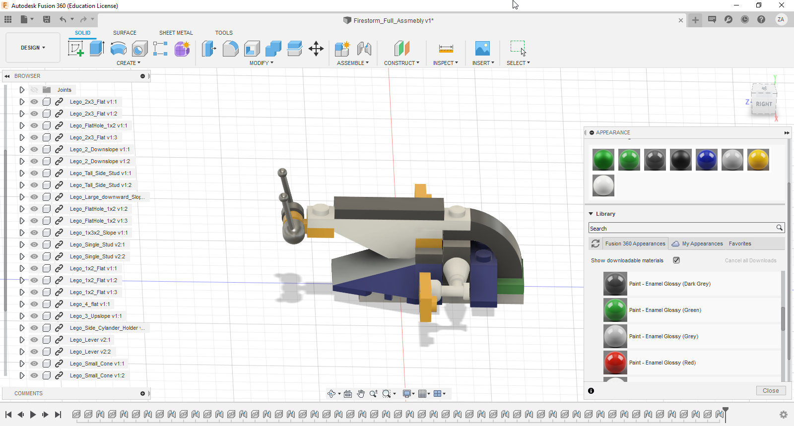
In Fusion 360, we use joints to constrain different models together, just like we did in the previous step. When you're finished, we'll have a model we can use to create drawings with. If you want to create visually appealing build instructions, I recommend saving build steps in separate files. You'll see why when we get to the exploded view step.
Step 1: Save an empty file
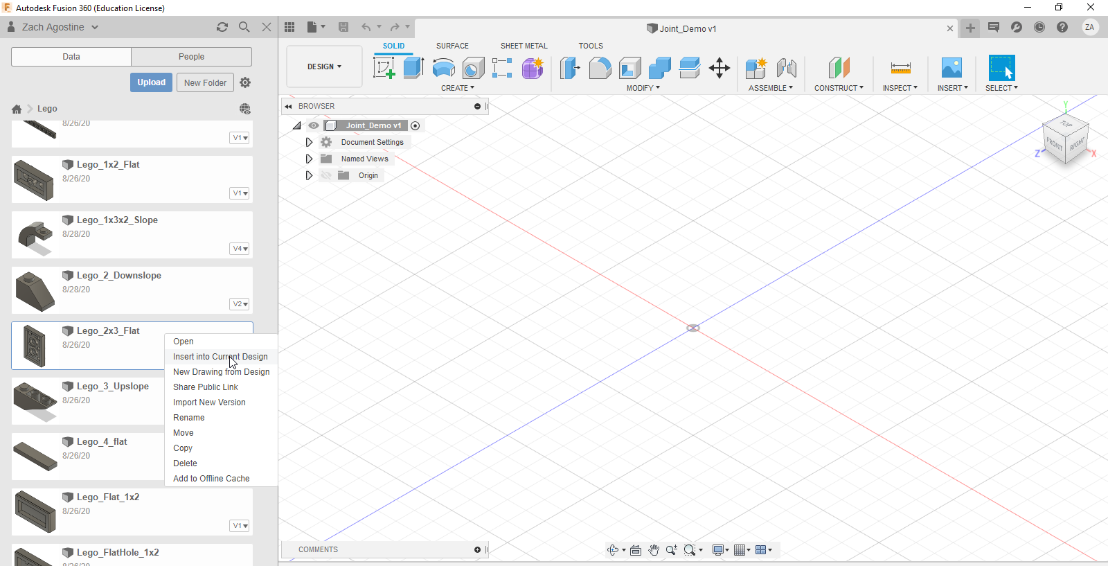
Fusion 360 wont let you import your bricks unless the file is saved.
Step 2: Import your first piece and ground it.
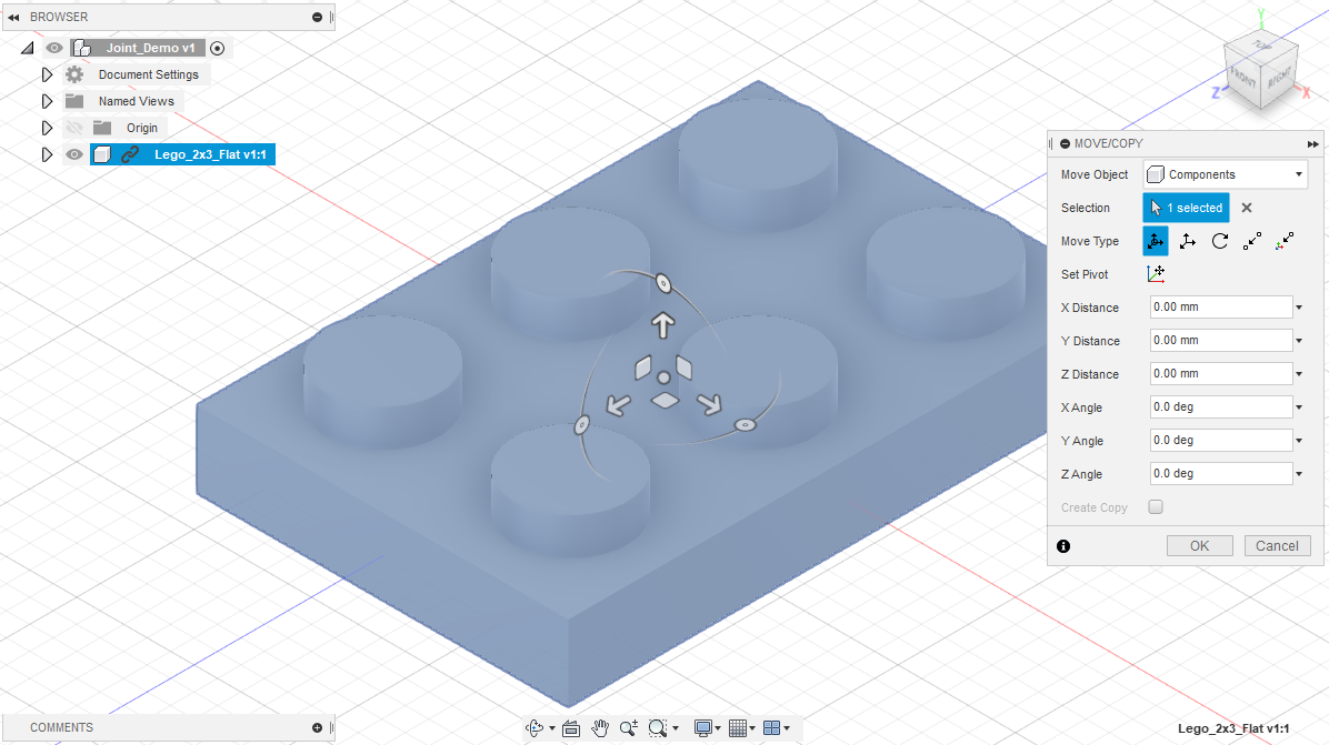
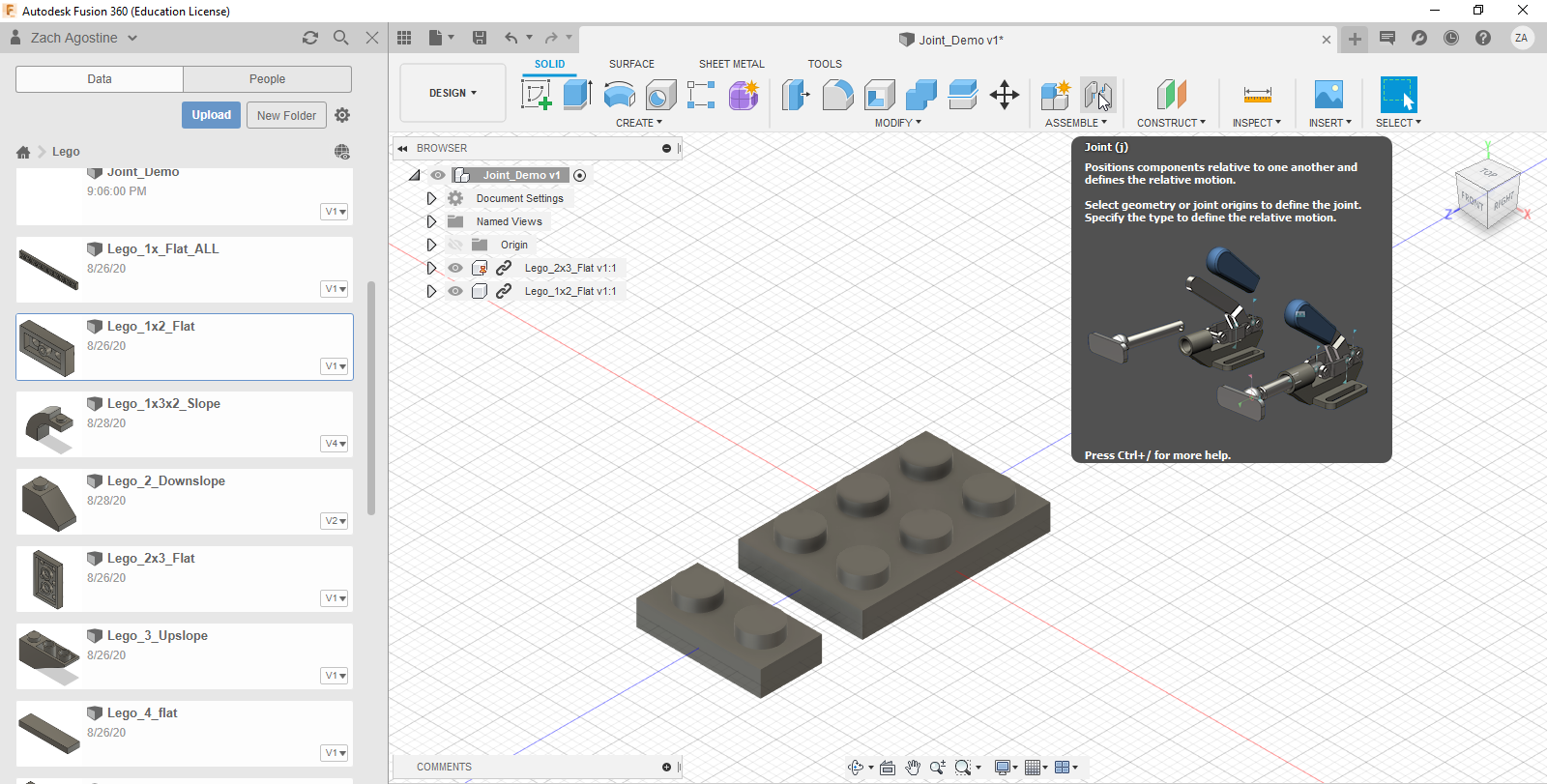
To add your first brick, open the data menu where all your parts are saved, right click your part, and click 'import into current design'. You will see options to move and rotate your piece. Once it is in the correct position and orientation, click 'Ok'.
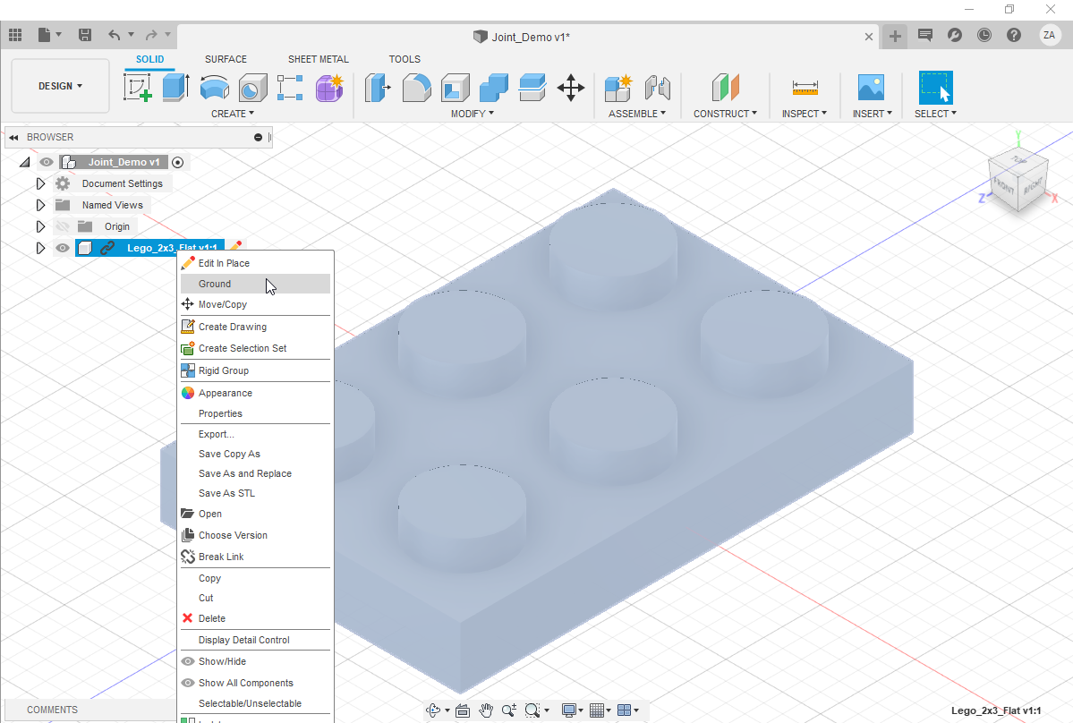
Grounding your parts keeps them in place. In the project drop-down menu, right click your part and click 'ground'. You'll see a red tack appear next to the part. You can ground parts as you build your model, making it easier to joint the new part to the build.
Step 3: Import a second piece.
Repeat the import process we used in step 2. To make jointing easier, I recommend moving the new part so it does not intersect with the other pieces. Click 'Ok' on the right side panel when you're finished.
Step 4: Create a joint.
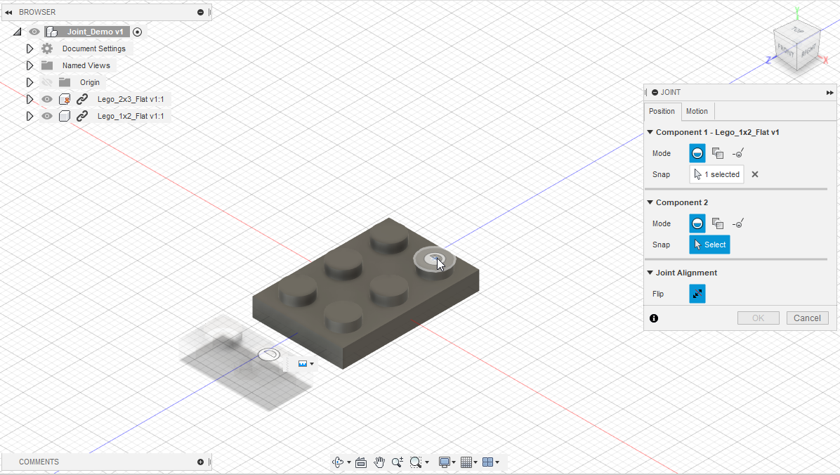
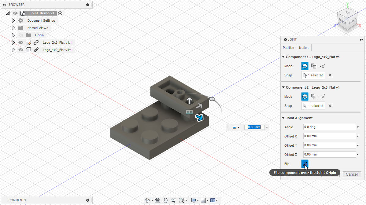
A joint is how we constrain 3D objects together - click the joint button to create one. You'll need to select a point on each object where you want to create a joint, then, you'll see an animation. Sometimes the joint will form an odd angle. Before you undo, you can try checking the flip option. You will also have one degree of freedom where you can move your part into position. If you are creating joints using studs (which I recommend) you will want to offset the bricks by 3.2 mm.
Step 5: Repeat steps 3 and 4 until your model is built - don't forget to save as you go.
(Optional) Create an Exploded View
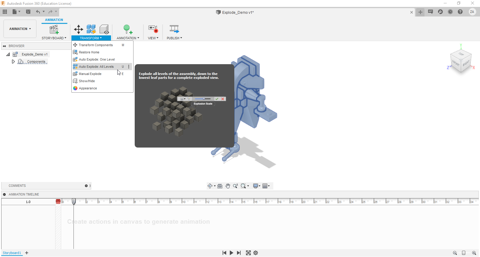
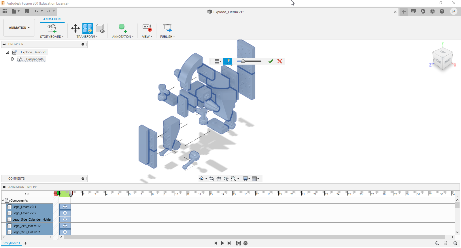
In the world of 3D modeling, complex assemblies can be difficult to visualize how everything fits together. The same can be said about Lego builds. To combat this, programs like Fusion 360 have an option to explode an assembly.
Here's how to do it:
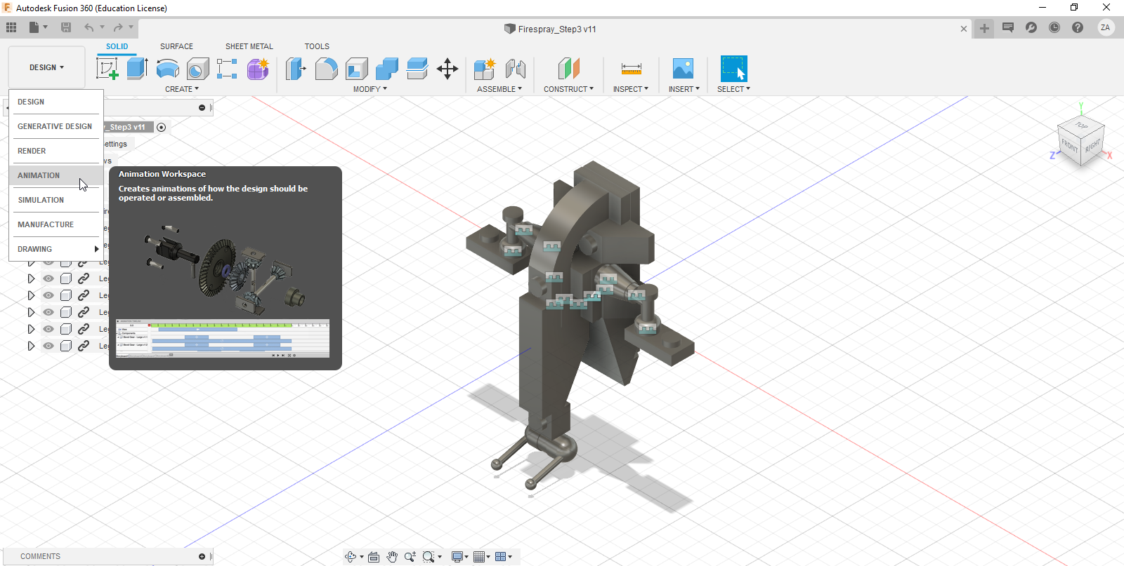
Step 1: Change your workspace to 'Animation'
Click on the workspace drop-down and select 'Animation'.
Step 2: Manual Explode Tool
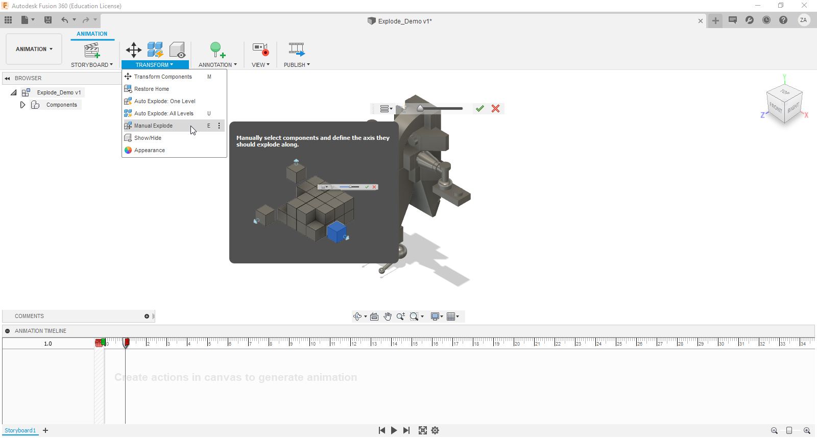
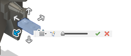
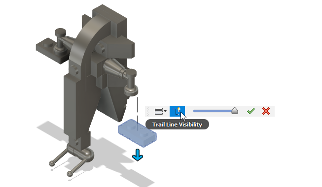
With your model in the animation workspace, click on 'transform', then, 'manual explode'. Click on the part you want to move. This will bring up the move tool. Pick a direction you want the part to move in, then adjust the slider to set distance. Toggle 'trail line visibility' to create a line showing where the part goes. I think it adds a really cool effect to the final product.
Continue this workflow until you are happy with the result. Remember, you can always edit parts that have already been moved by applying a new manual explode to them.
Step 3: Auto Explode and why I don't recommend it for this project
You also have the option to explode every part in one step. The trouble is that Lego builds have a lot of small pieces very close together. Having them set to close together is going to block a lot of detail from being shown during the final carve. Having all these parts too far apart creates a different problem. You tend to loose the overall shape of the final build since the eye doesn't have any profiles to focus on.
If you want to create build instructions the way I did, do exploded views for each of your build steps. This will allow you to show the full build process while also giving you clear and well defined steps.
Create a Drawing
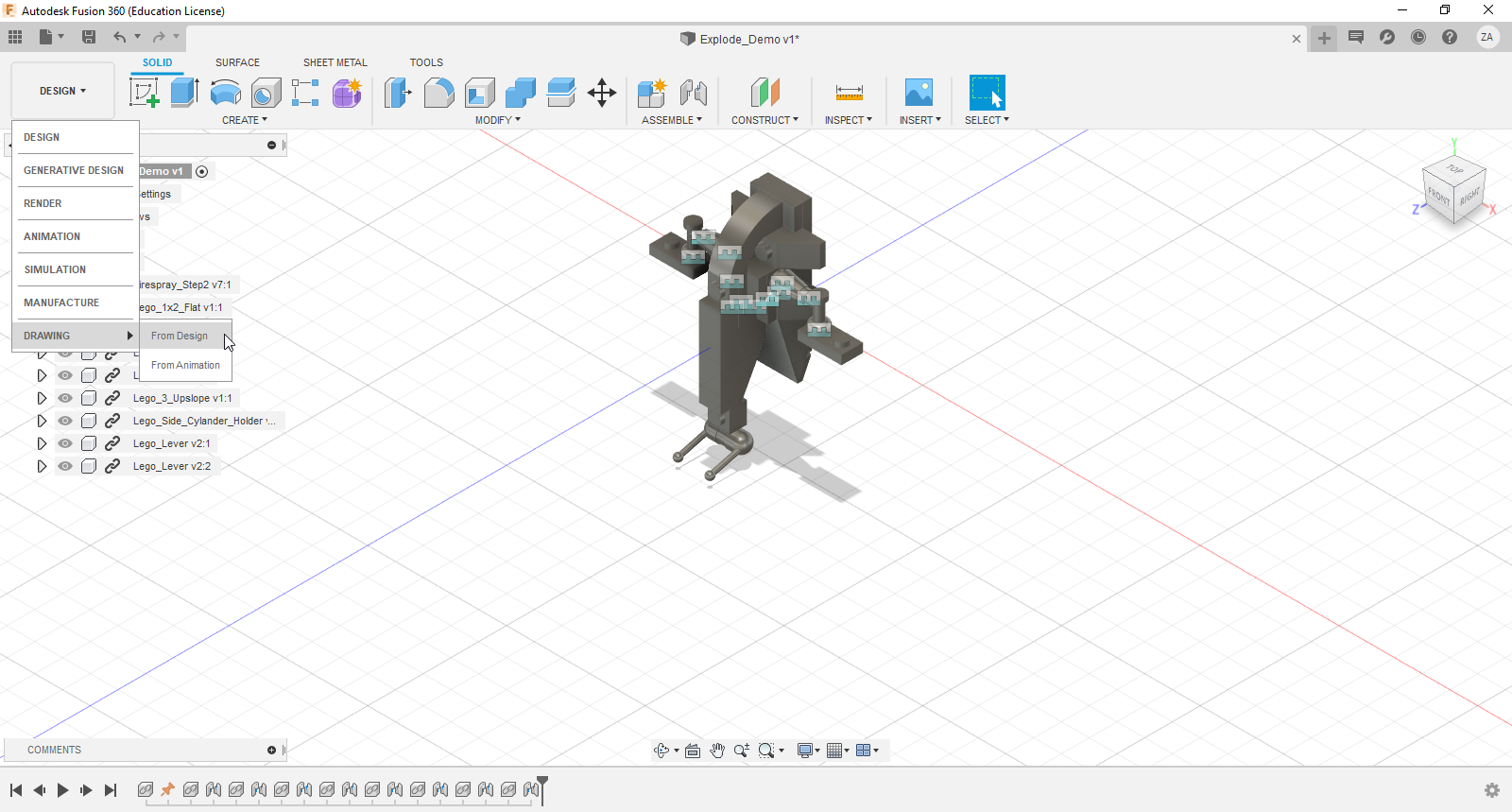
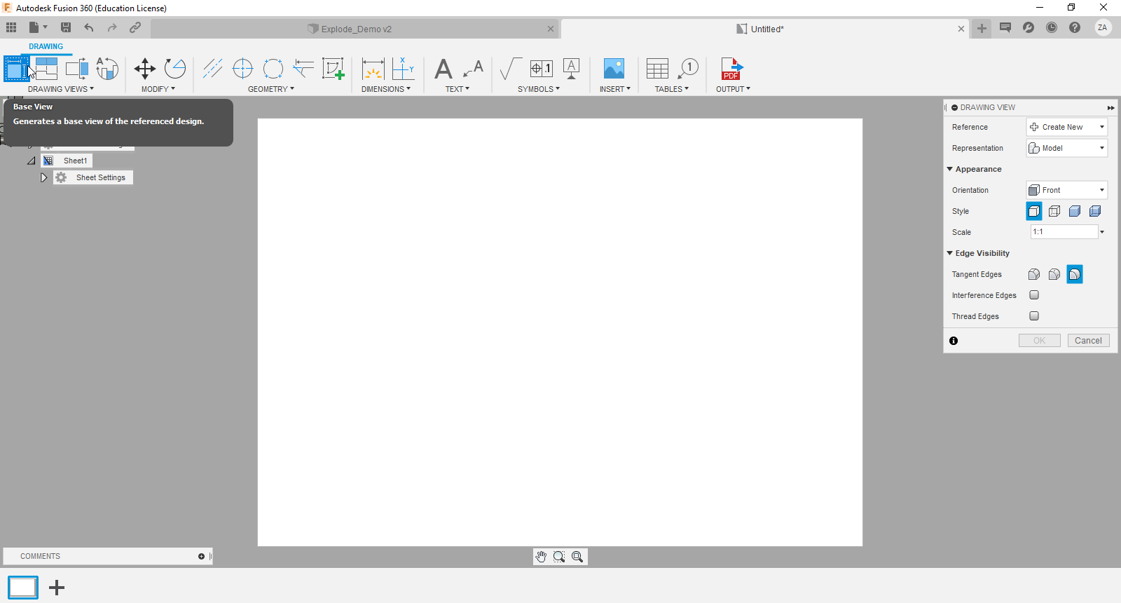
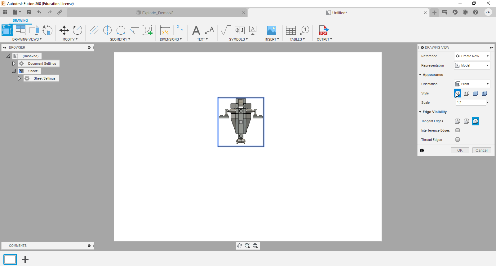
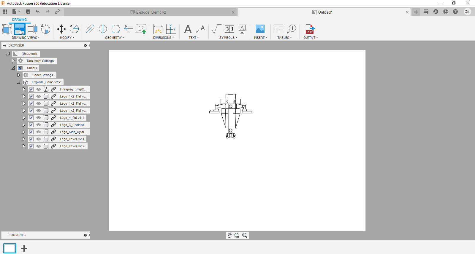
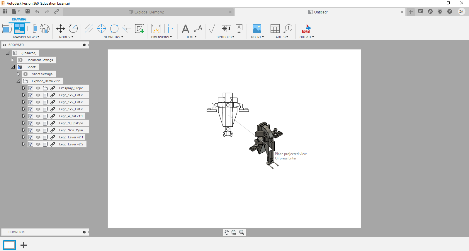
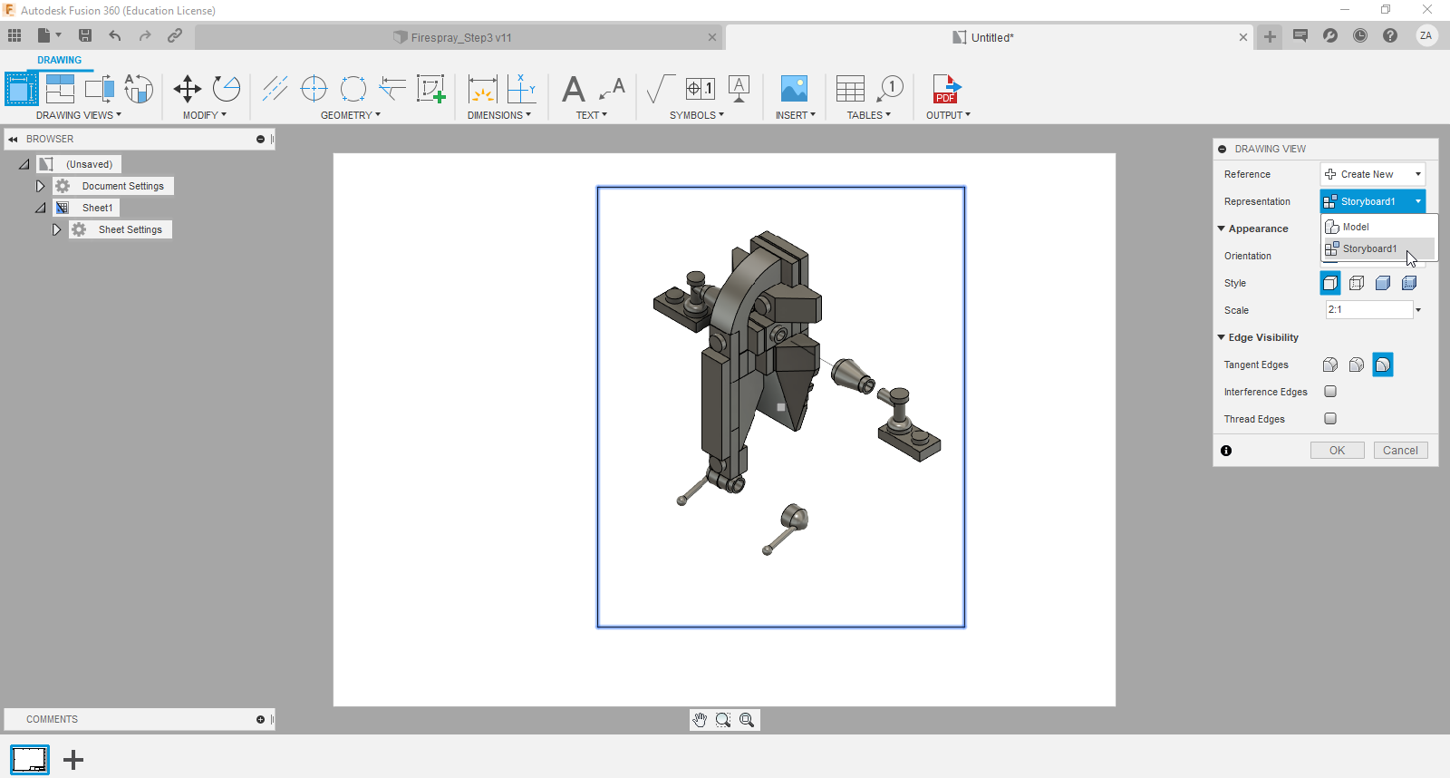
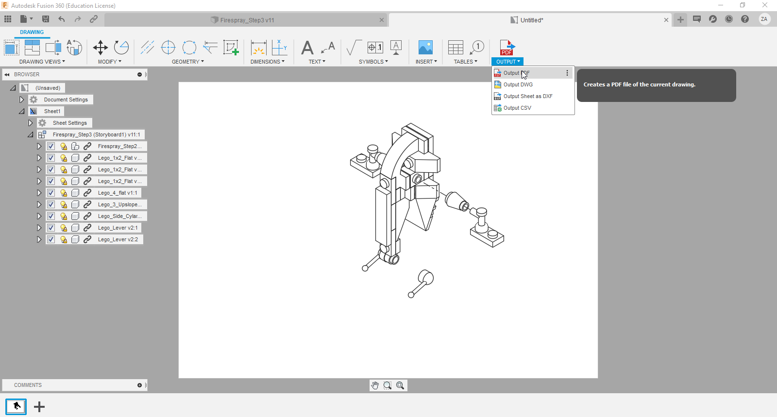
A drawing is used to show a projected 2D view of a 3D object. By creating drawings, we convert the awesome model into drawings we can use on our CNC machine.
Here's how to do it:
Step 1. Switch to the 'Drawing' workspace
Change your workspace to 'Drawing', then, 'From Design'.
Step 2: (Optional) Clear you drawing space
When a drawing is created, there are two graphics already present - the display border and the tile block with drawing information. You can keep these for an extra layer of cool on your final design, but I prefer to remove them. Simply click on the object, then press delete.
Step 3: Place your base/projected views
Click on the 'base view' button. You'll see a panel appear on the right side of your screen with options for your drawing. The 'orientation' drop-down allows you to select different views, both flat (top, front, etc) and isometric. Next to 'style' there are 4 options for how your drawing is shaded and which lines are visible. For this project I use the far left option, 'visible edges' so we get clean outlines.
Step 4: (Optional) Place your exploded view
If you created an exploded view, click on the 'representation' drop-down. You'll see an option titled 'Storyboard1'. This is your exploded view, so select it and place it on the drawing.
Step 5: Export
Click on the export button and save the drawing as a PDF.
Convert Your PDF to an SVG

Since my only option to export a drawing was a PDF, I need a way to convert the file into an SVG format. SVG stands for scalable vector graphics, and is a common file type used by cnc machines.
To do this, download and install Inkscape (https://inkscape.org/). Once installed, simple import the PDF and save it as a SVG. Normally, I'd recommend creating a bitmap trace to help with cutting accuracy, but that doesn't appear to be an option with PDFs.
If anyone has an explanation for this, please let me know!
CnC Setup and Carving
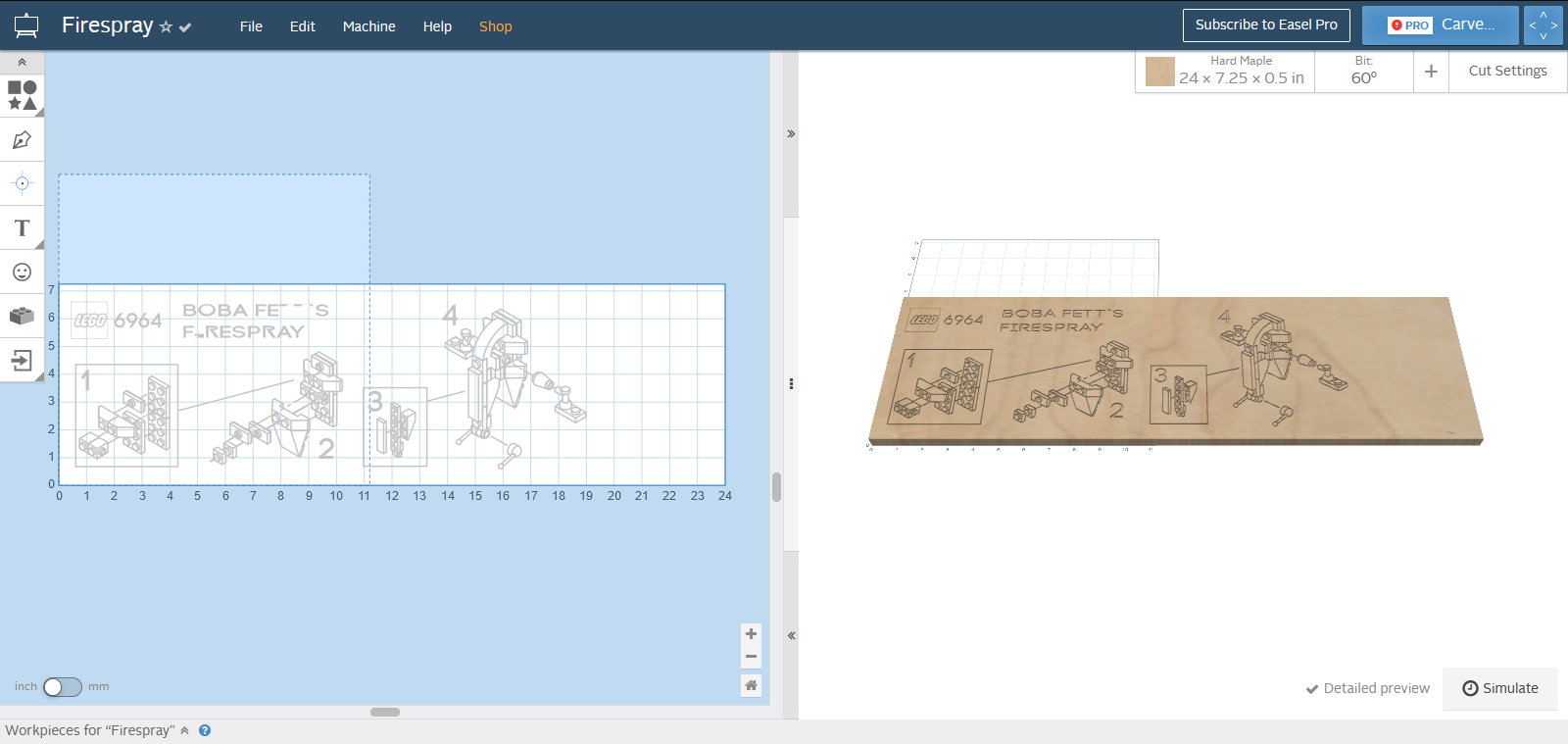
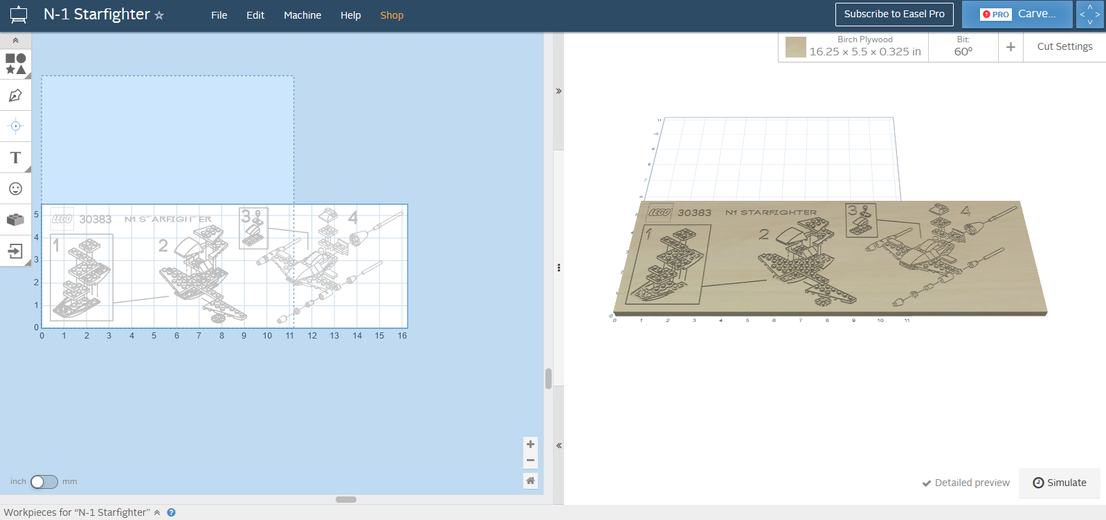
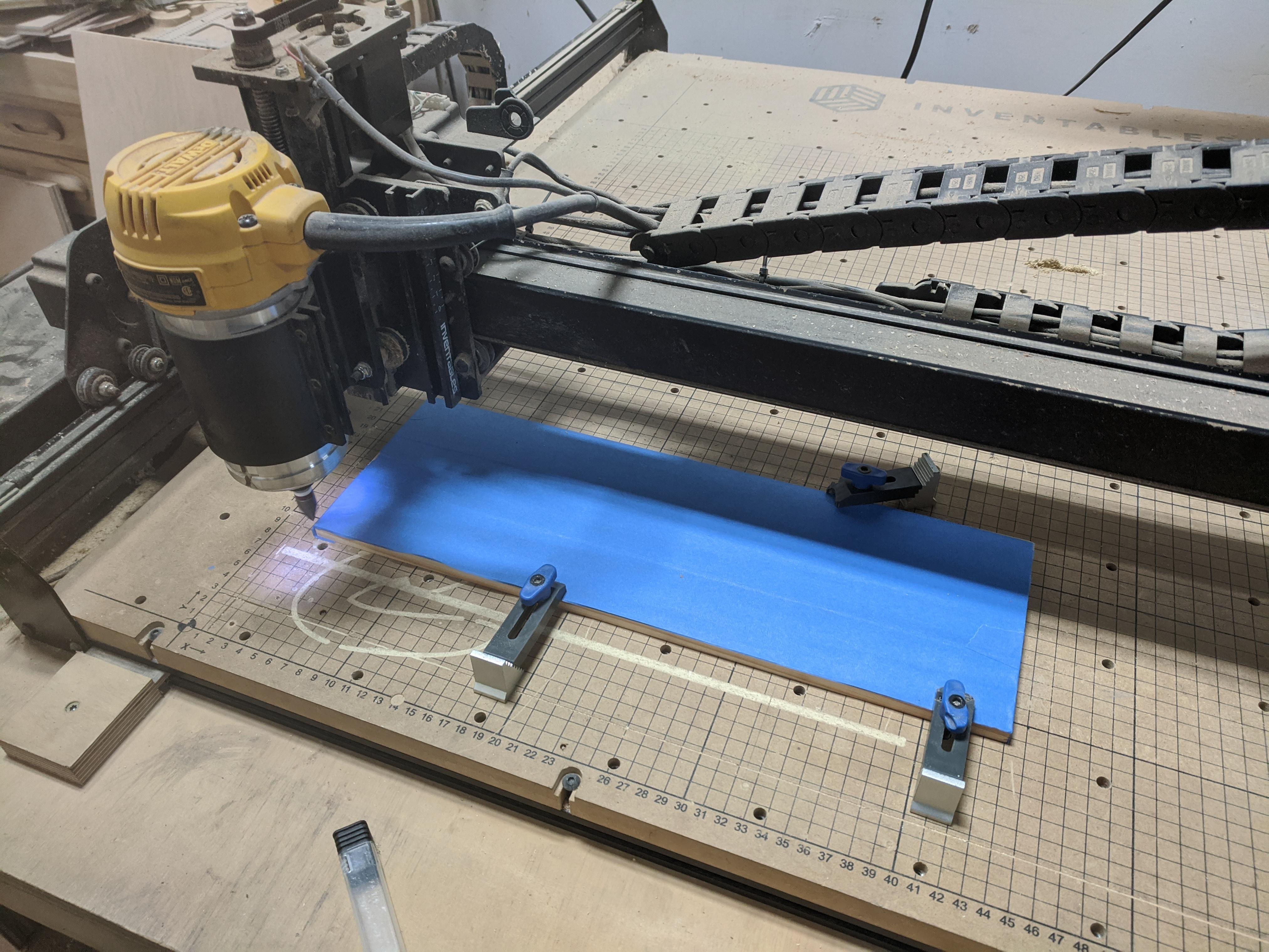
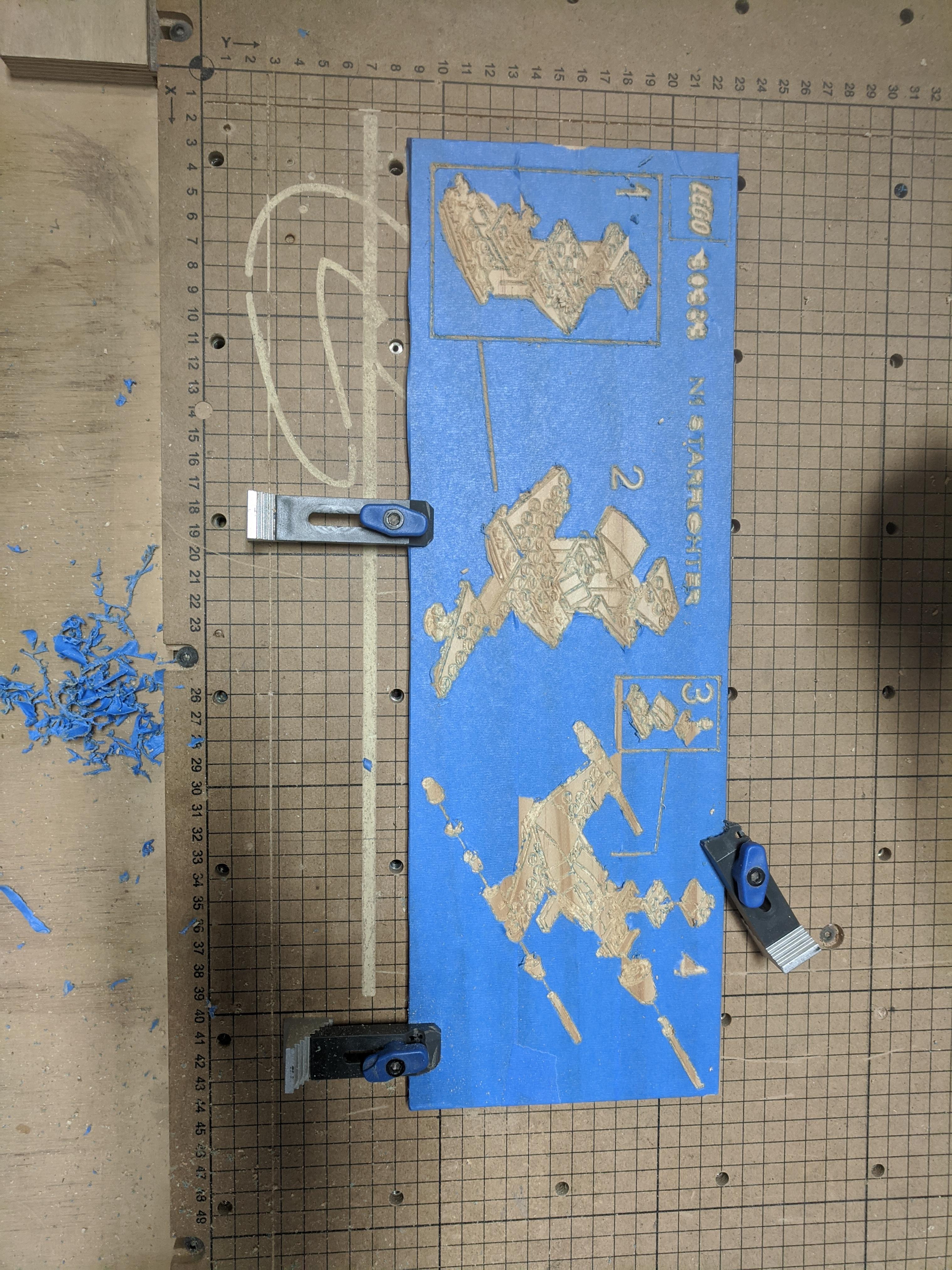
My local maker space has an X-Carve CnC machine which I used to carve my final product. If you are interested in getting started with CnC, I recommend looking for maker spaces and fab labs near you. Not only do they have a lot of expensive equipment available, they have several trained staff who can get you up and running a lot faster than trying to teach yourself.
Here's how I carved my board:
The X-carve uses a web-based software called Easel. I started by setting the dimensions of my workspace so I wouldn't accidentally carve outside of my board. I uploaded all of my new SVG files and began placing them in the workspace. I added an SVG Lego logo, set number, and name for some aesthetic touches. Once everything was placed where I wanted it, I set my cut depth to 0.04 in. This is important because the bit I'm using is a 60 degree V-bit. These bits have extremely fine tips that can create very precise cuts. Cutting too deep will degrade the overall detail.
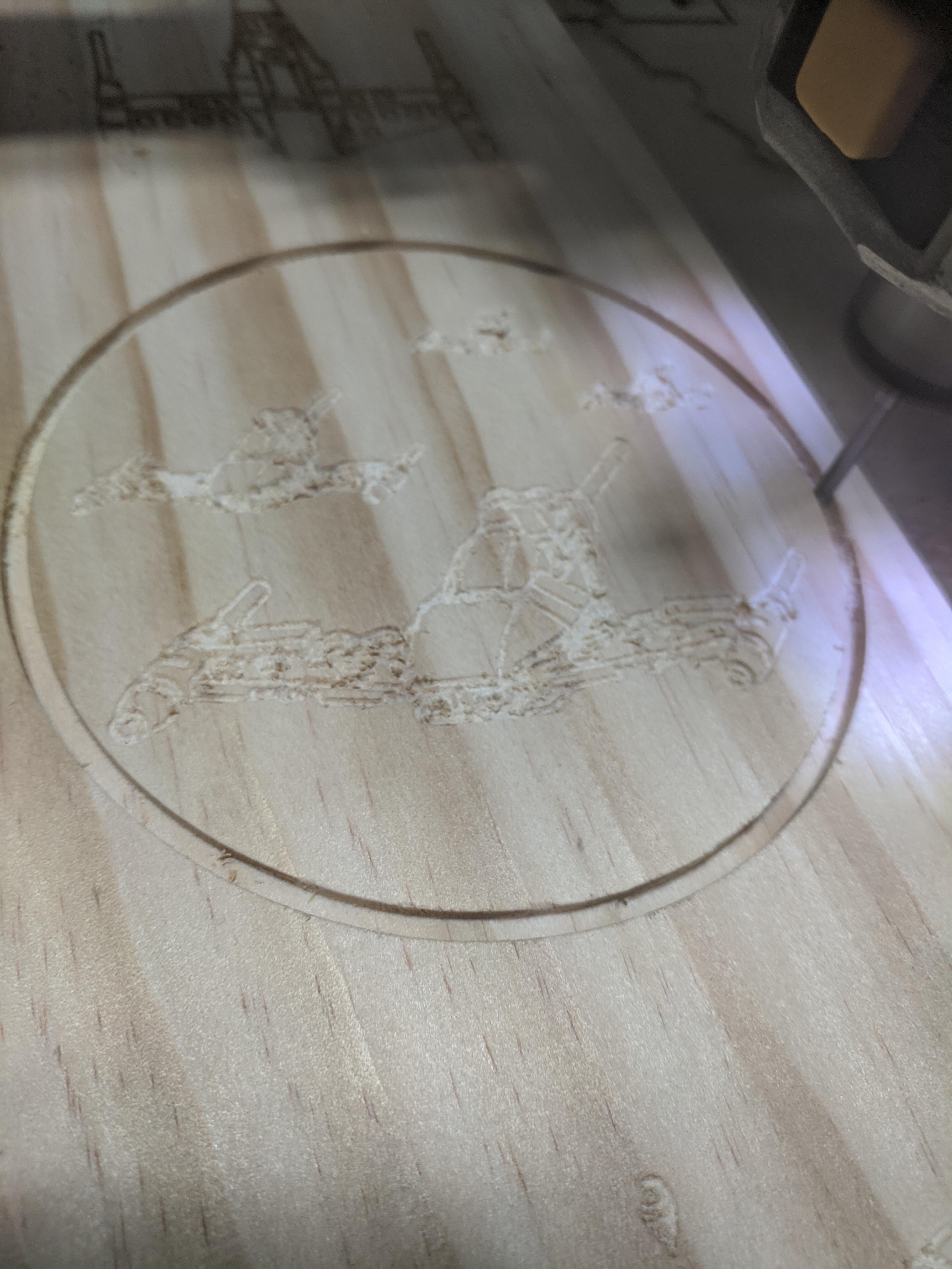
In the materials section, I recommended using hardwood such as oak. In this project, we are carving a lot of fine details very close together, and a lot of quality can be lost when using a soft wood. You can see on the coasters, which are made of pine, a lot of the smaller areas don't stand out as well.
Once I was happy with my cut path, I secured my material to the bed, changed the bit to the 60 degree one, set a home position, then pressed carve!
If you're using a soft wood, or plan on painting it, I recommend taping your board pre-cut. This will save you time on sanding the negative space, and make crisp lines if you're using spray paint.
Post Processing
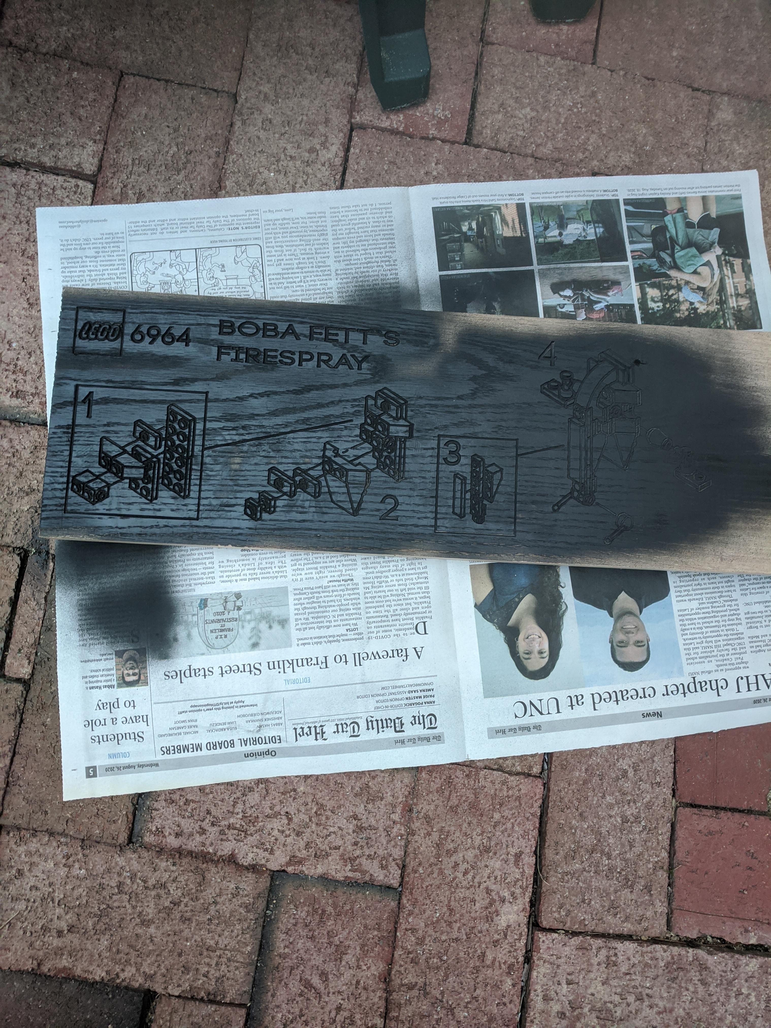
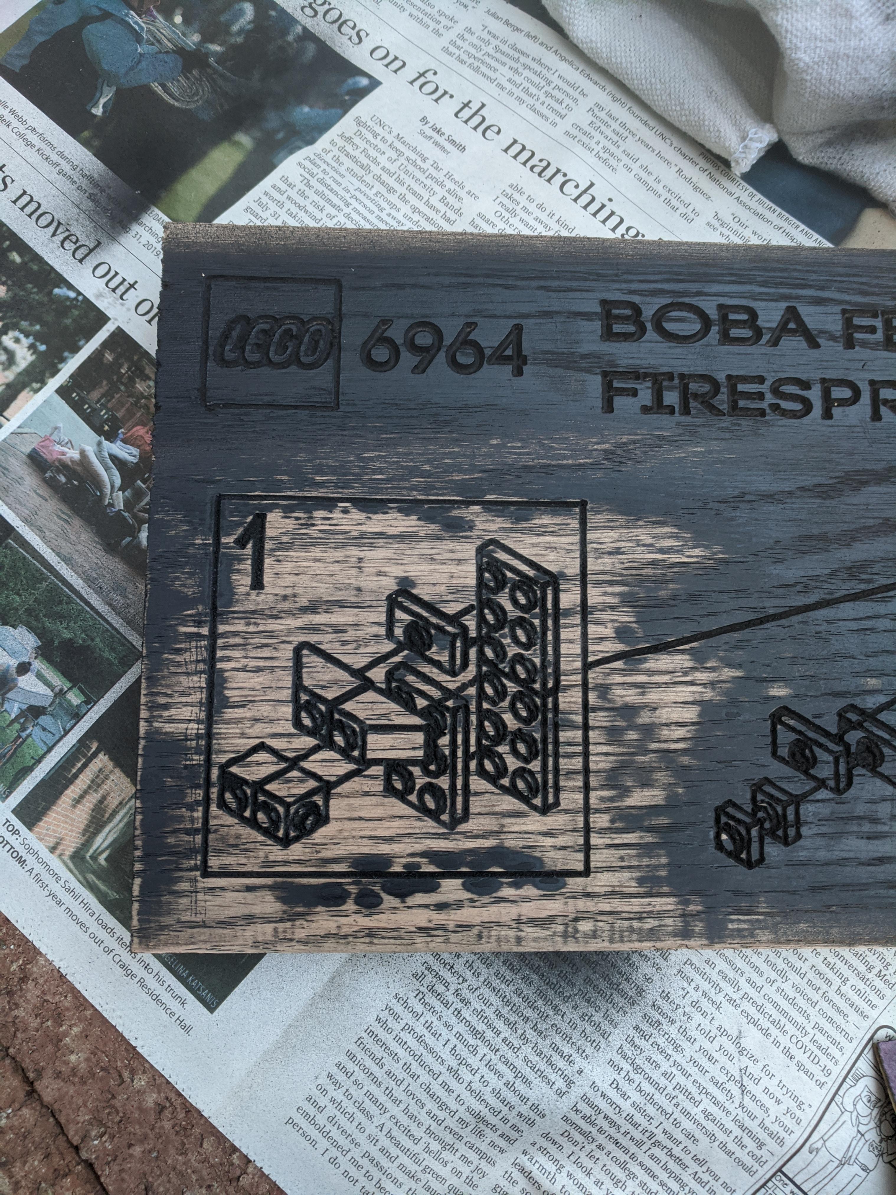
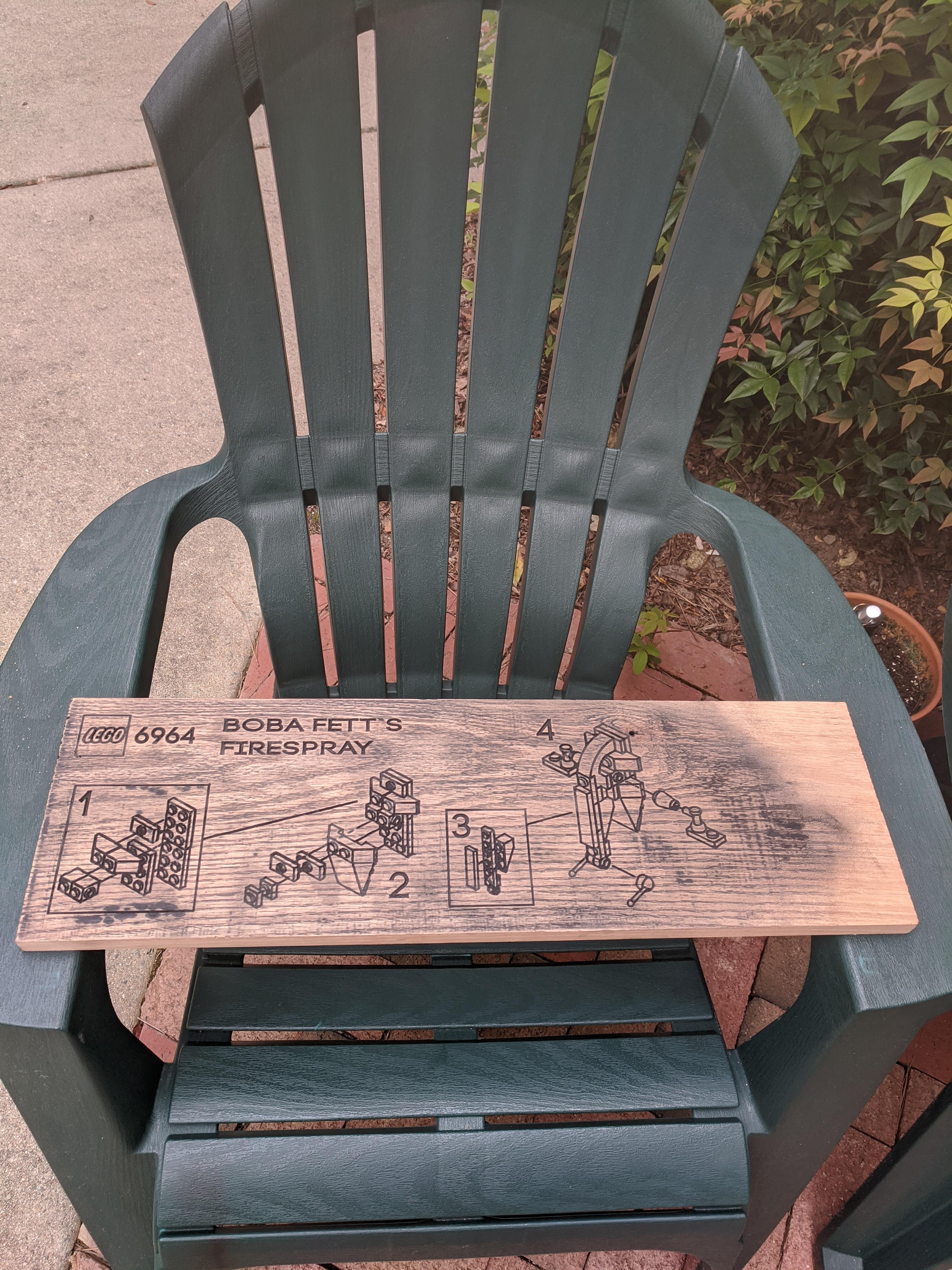
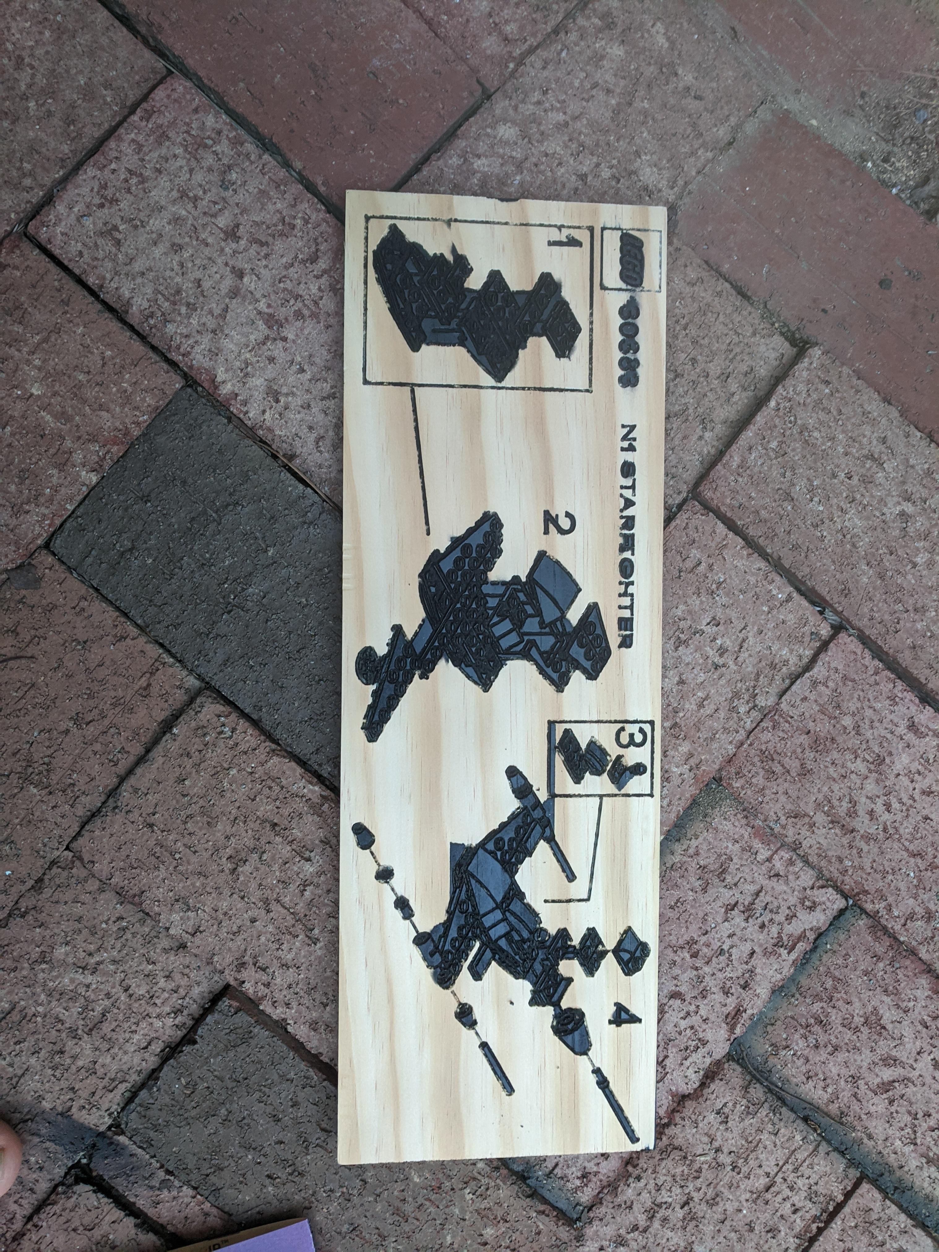
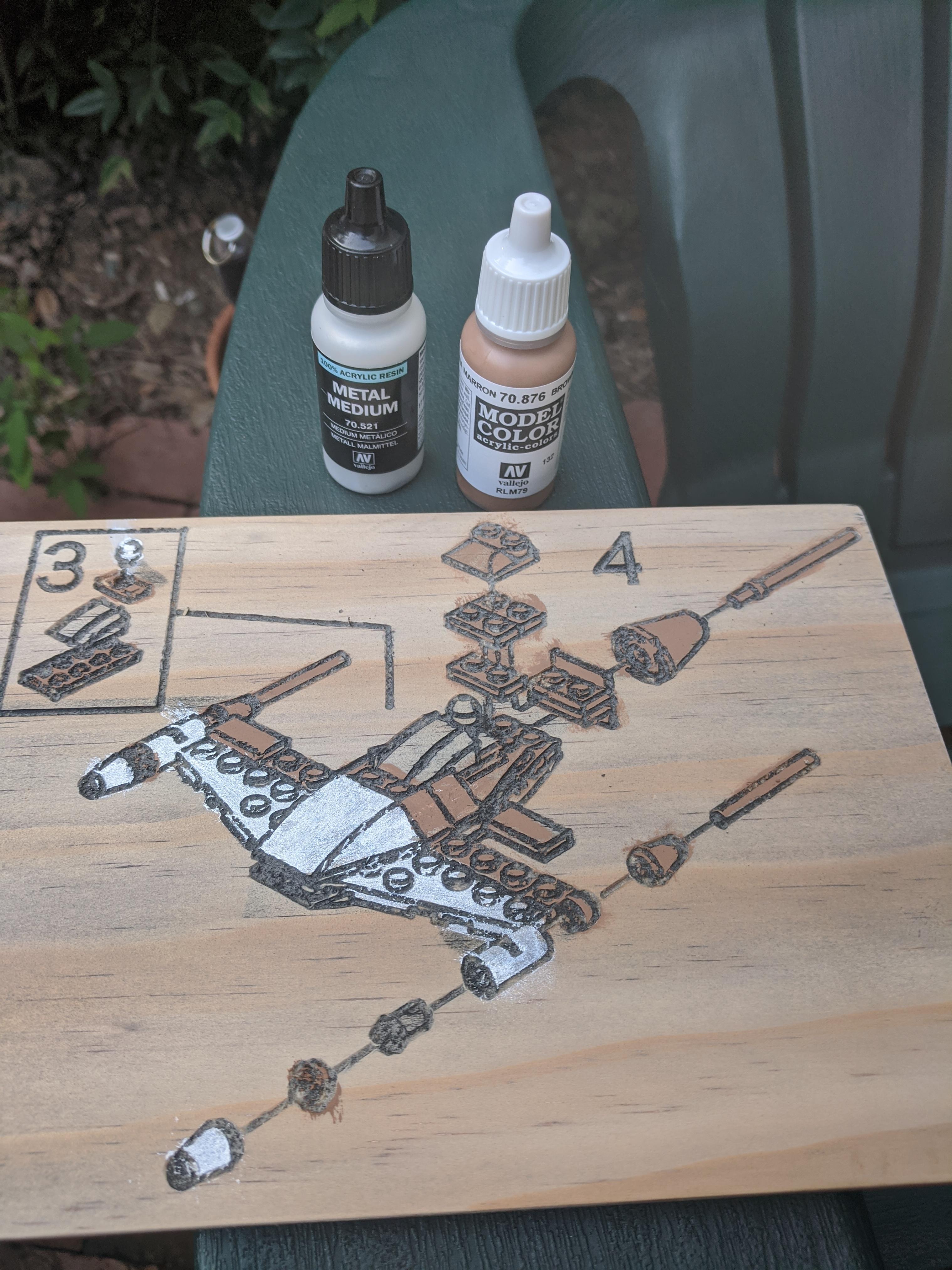
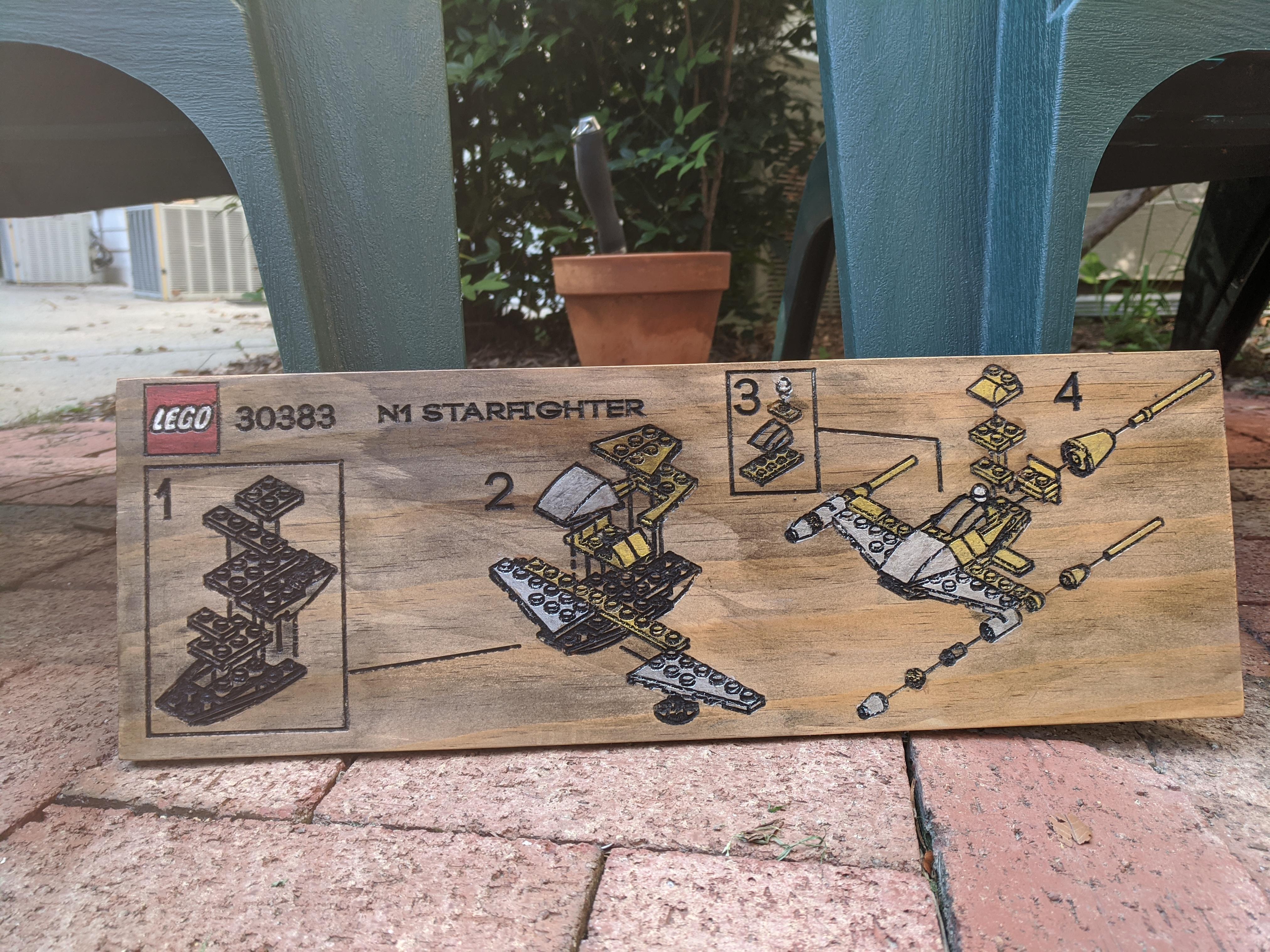
My final cut turned out great, but there is still a bit of work to be done before it is ready.
First, I did an initial sanding pass with some 220 grit sandpaper. This removed some of the raised edges on the vertical cuts, and prepare the wood for paint.
Next, I used the edge of some 400 grit sandpaper to clean and smooth the cuts. This removes any large debris and keeps the channels free from sawdust.
I sprayed the board with some black primer spray paint. I rotated the board 180 degrees and sprayed it again. This ensured that the entire cut channel was covered in paint.
Once dry, I spent a good 2 hours sanding the board with 400 grit sandpaper. Not only did the cuts become crisp and clear, but it gave the board a slightly weathered look that I'm very happy with.
Finally, I wiped down the board with my tack cloth to remove all the loose particles. If you want, you can use some wipe-on polyurethane or some linseed oil to preserve the final piece.
On my pine board, I tried adding color using basic acrylic paints. The final effect was nice, though I wish there was more fine detail. Again, hardwood is the way to go.
And that's it! Thank you for sticking around to the end and I hope you enjoyed the journey!
Bonus: Making Coasters and Learning From Mistakes

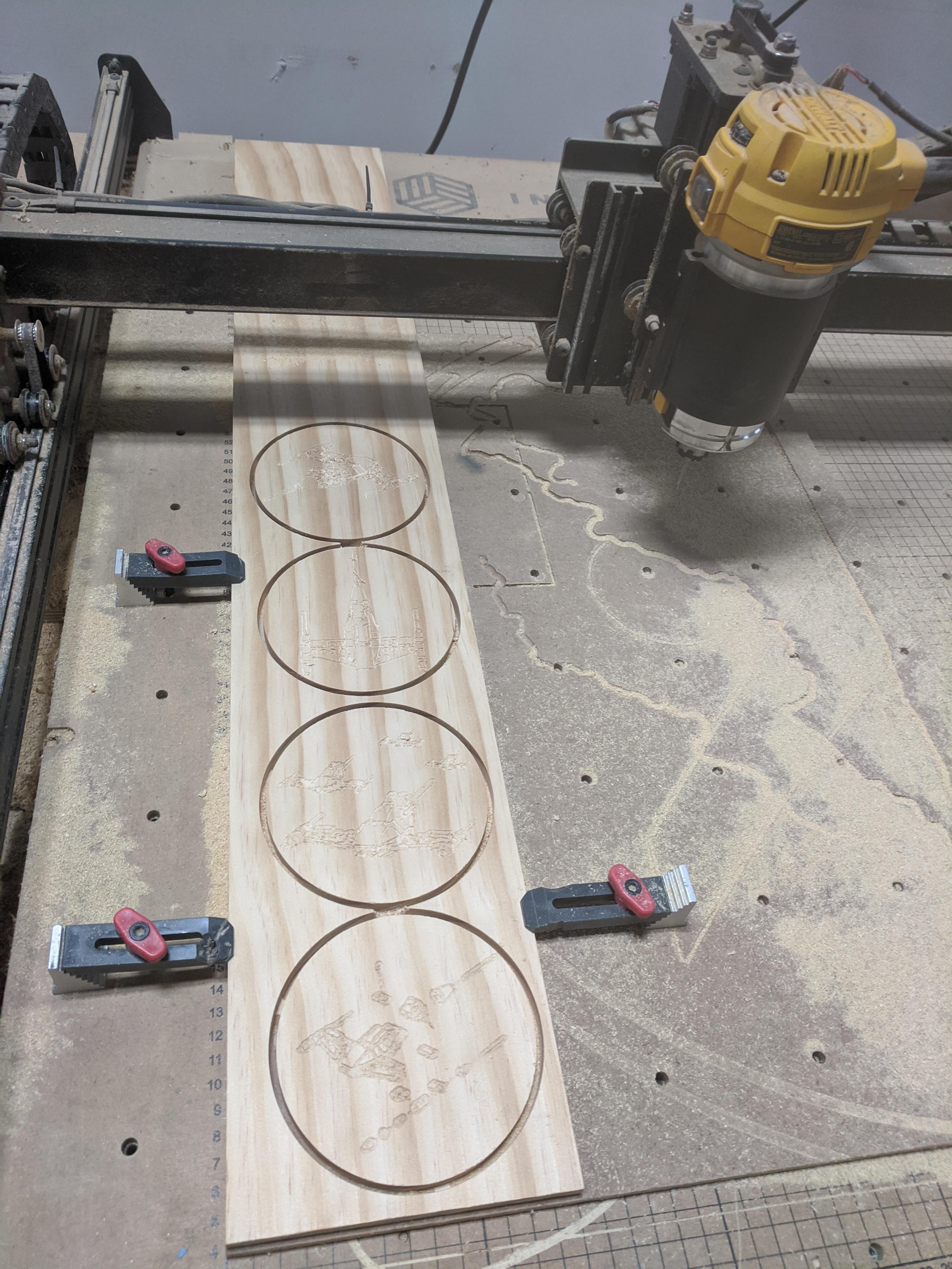
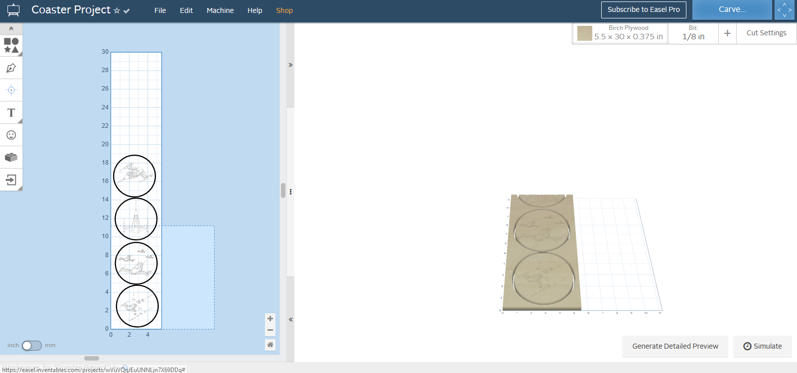
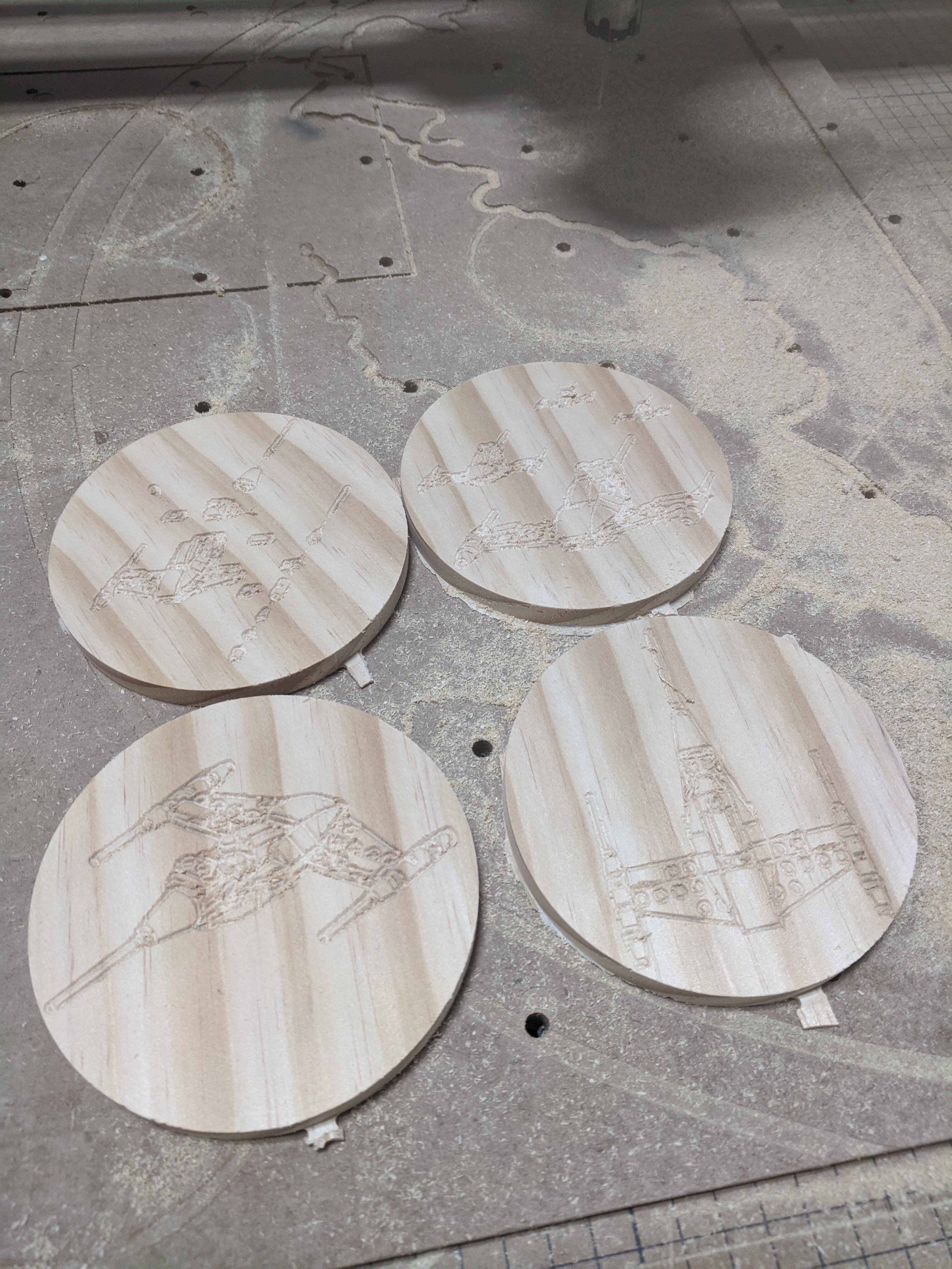
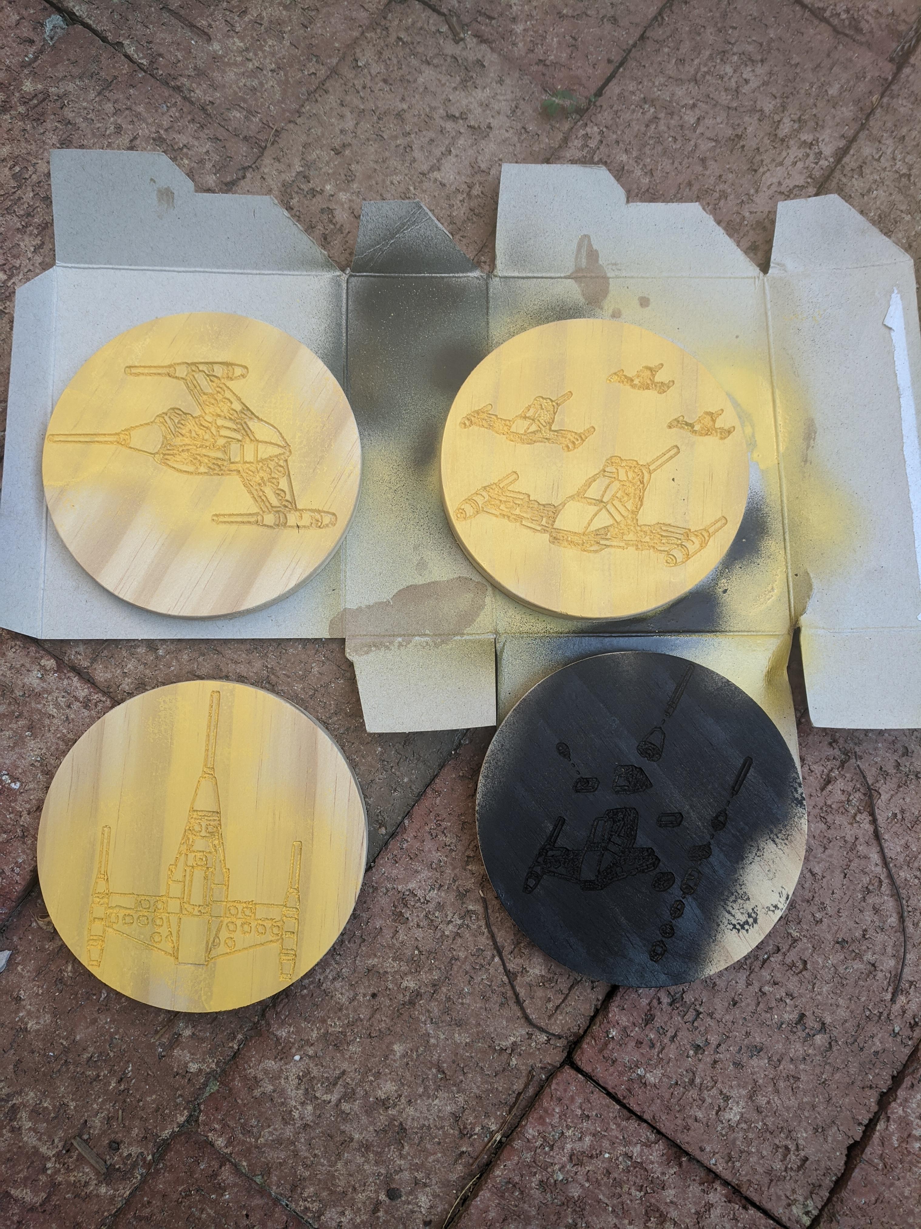
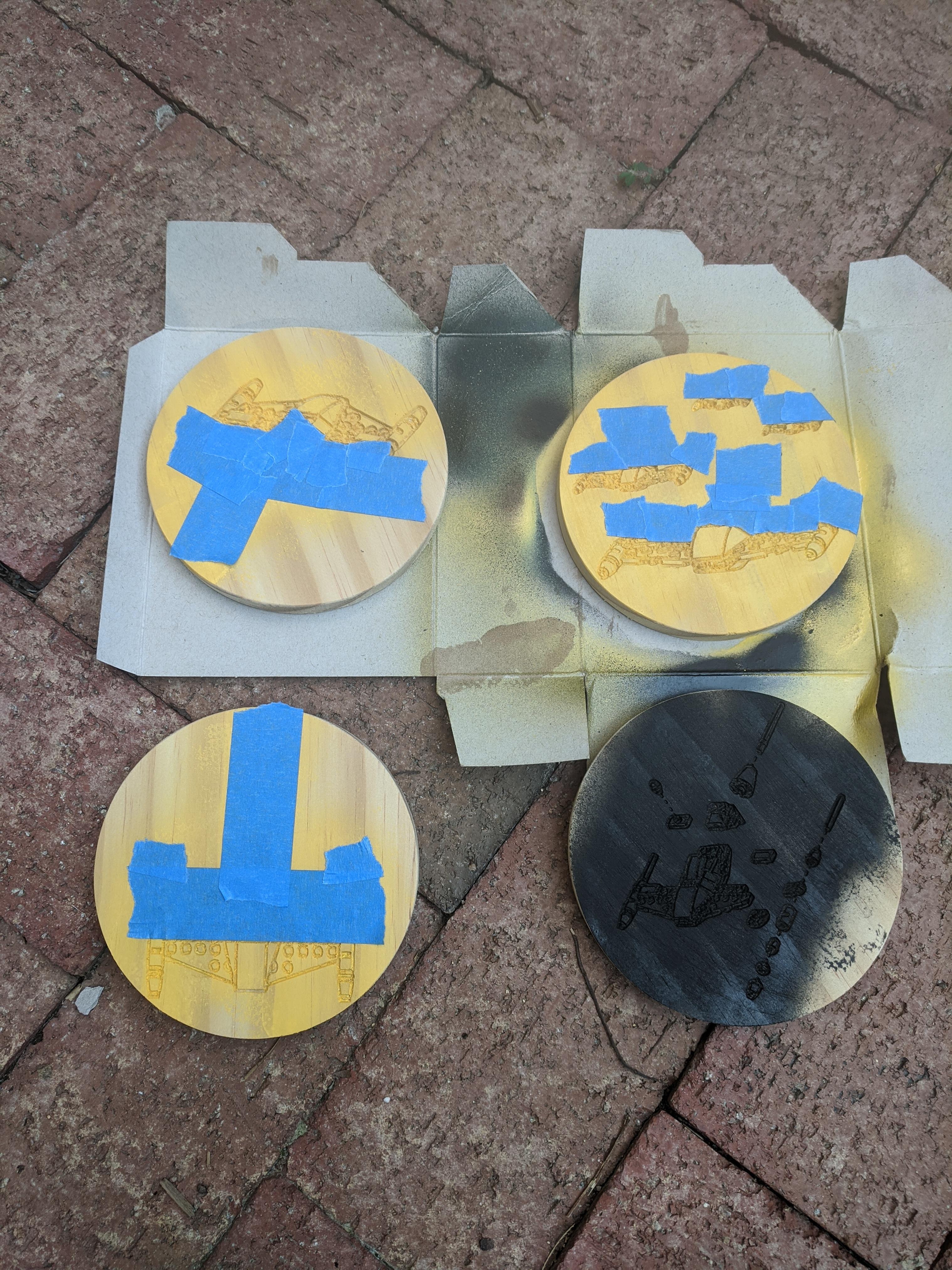
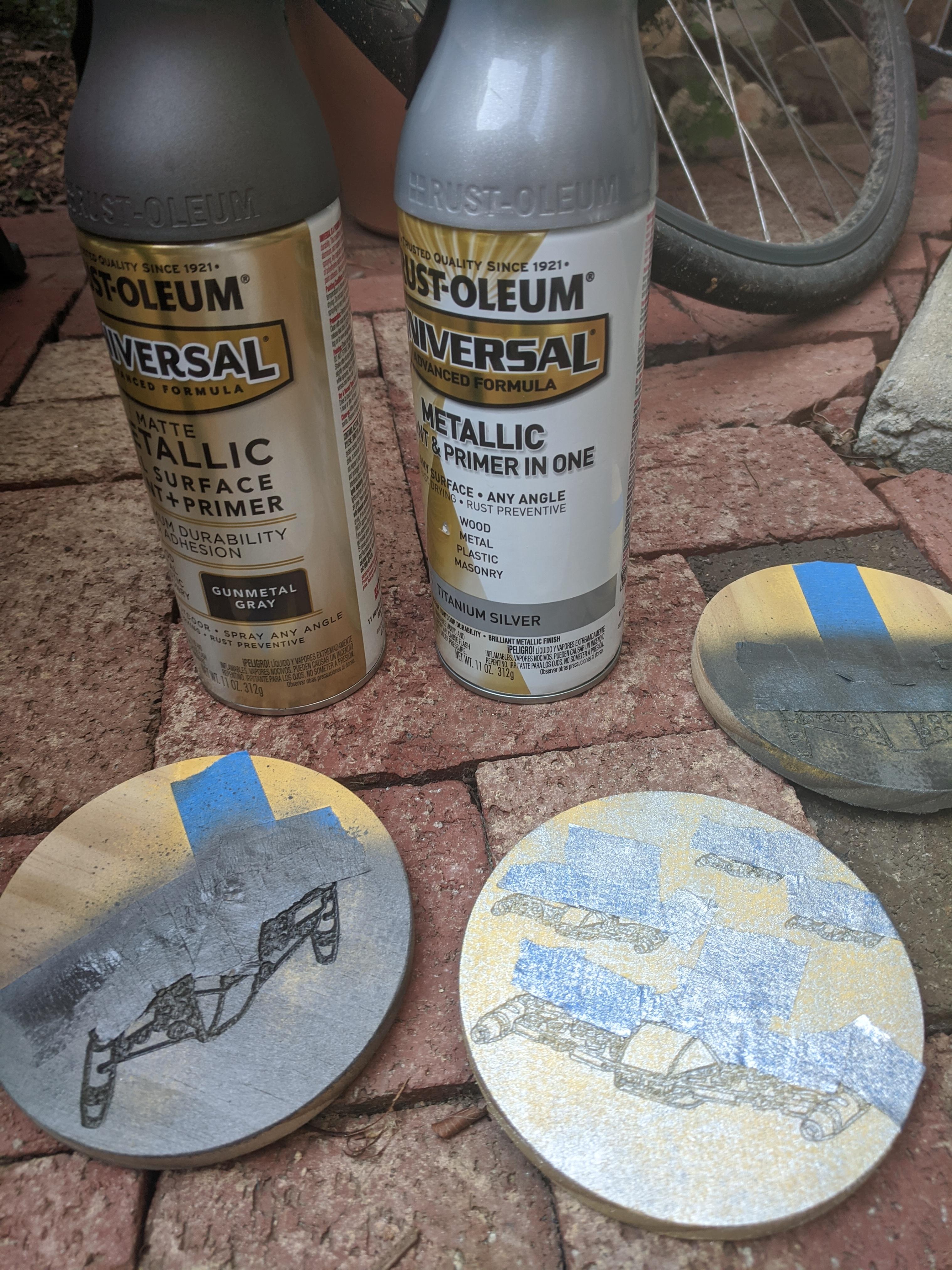
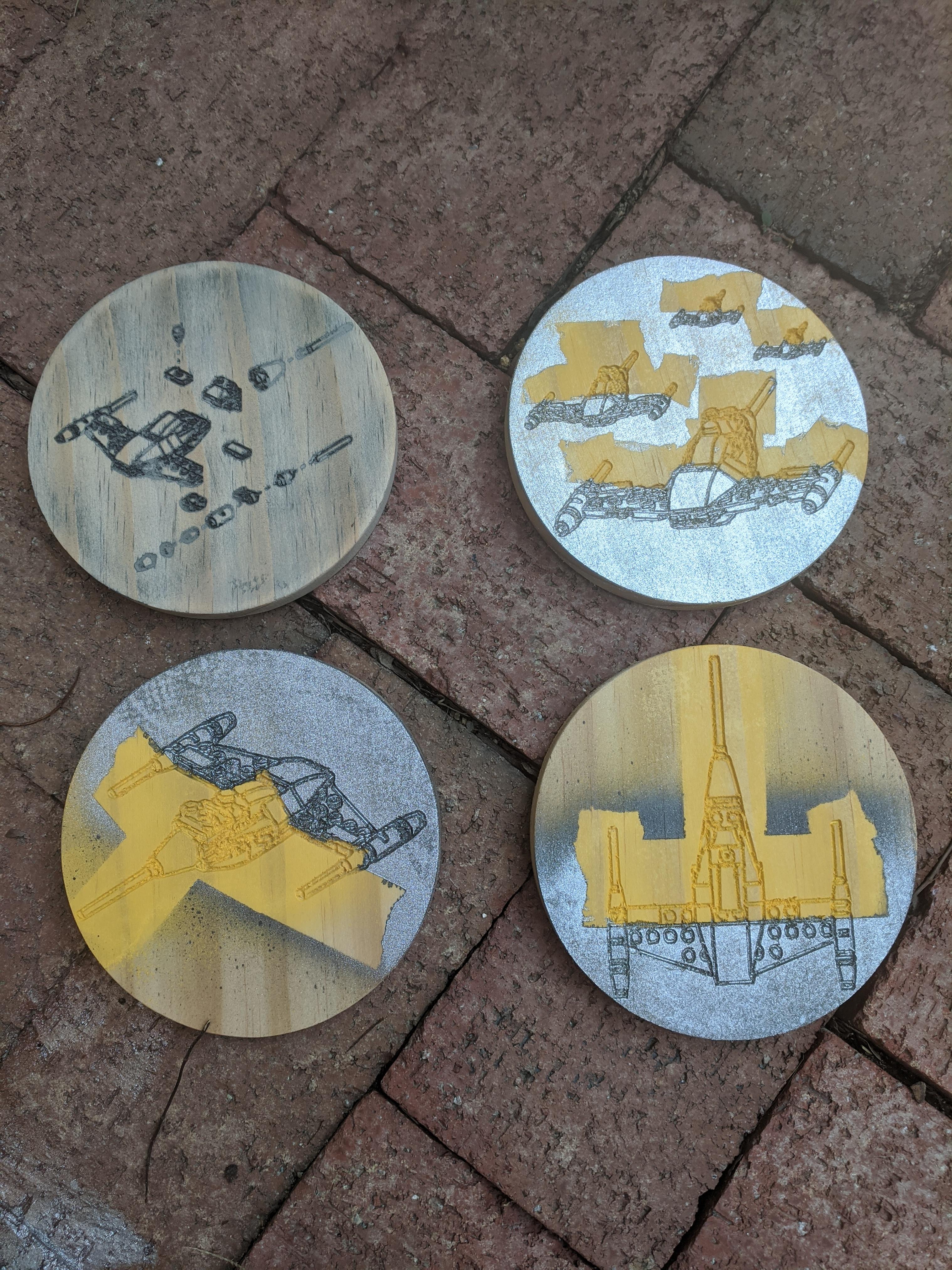
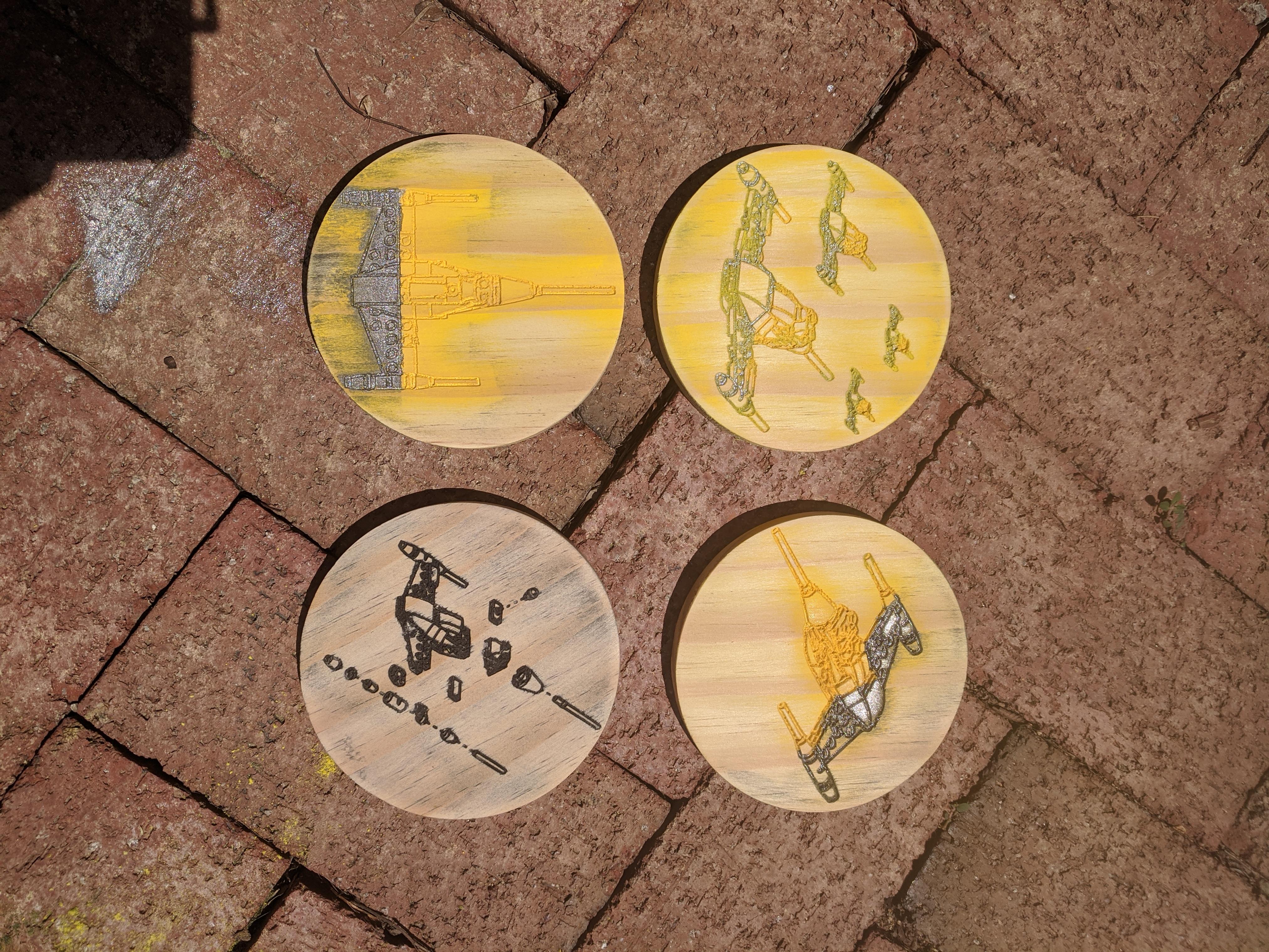
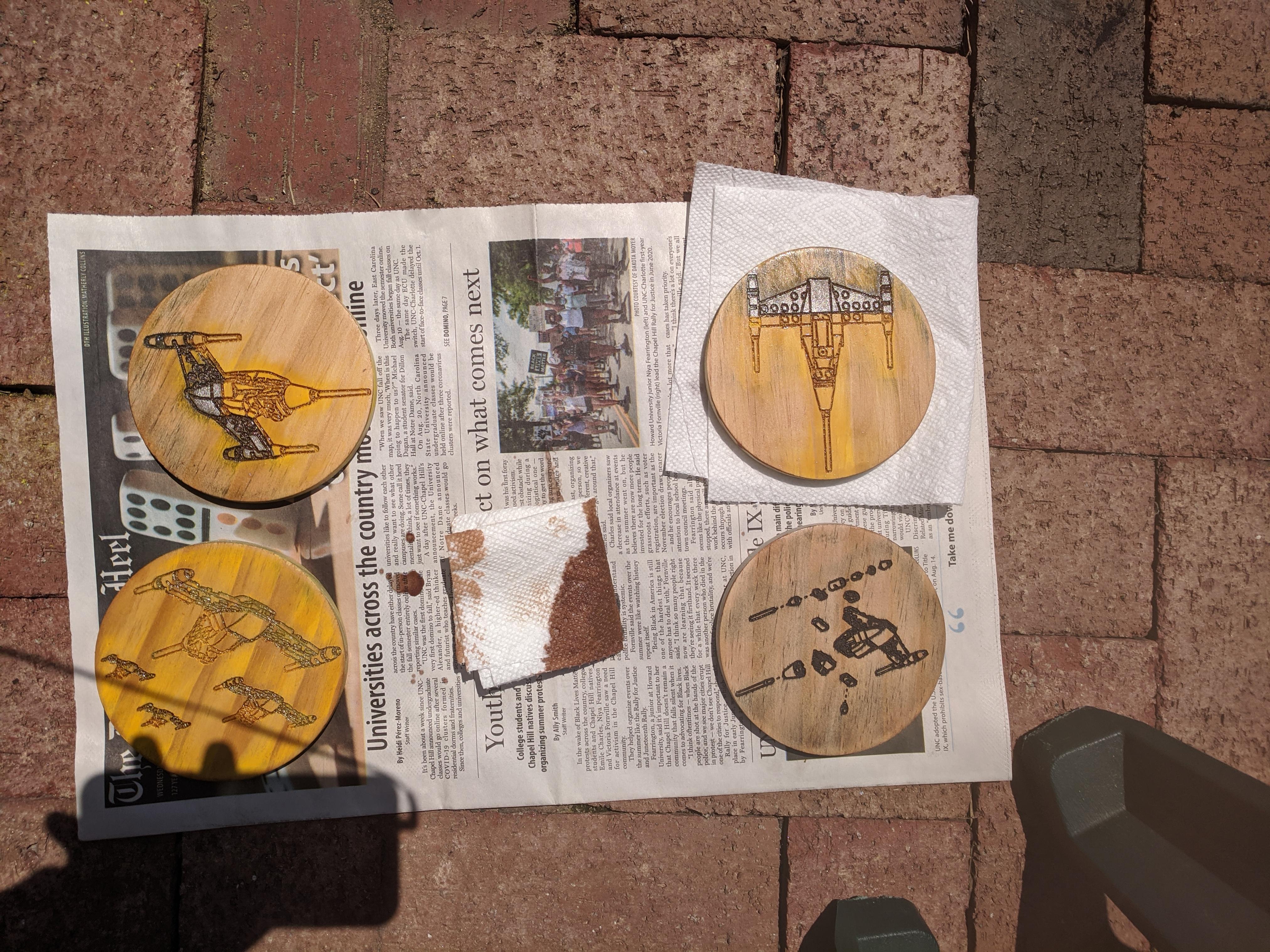
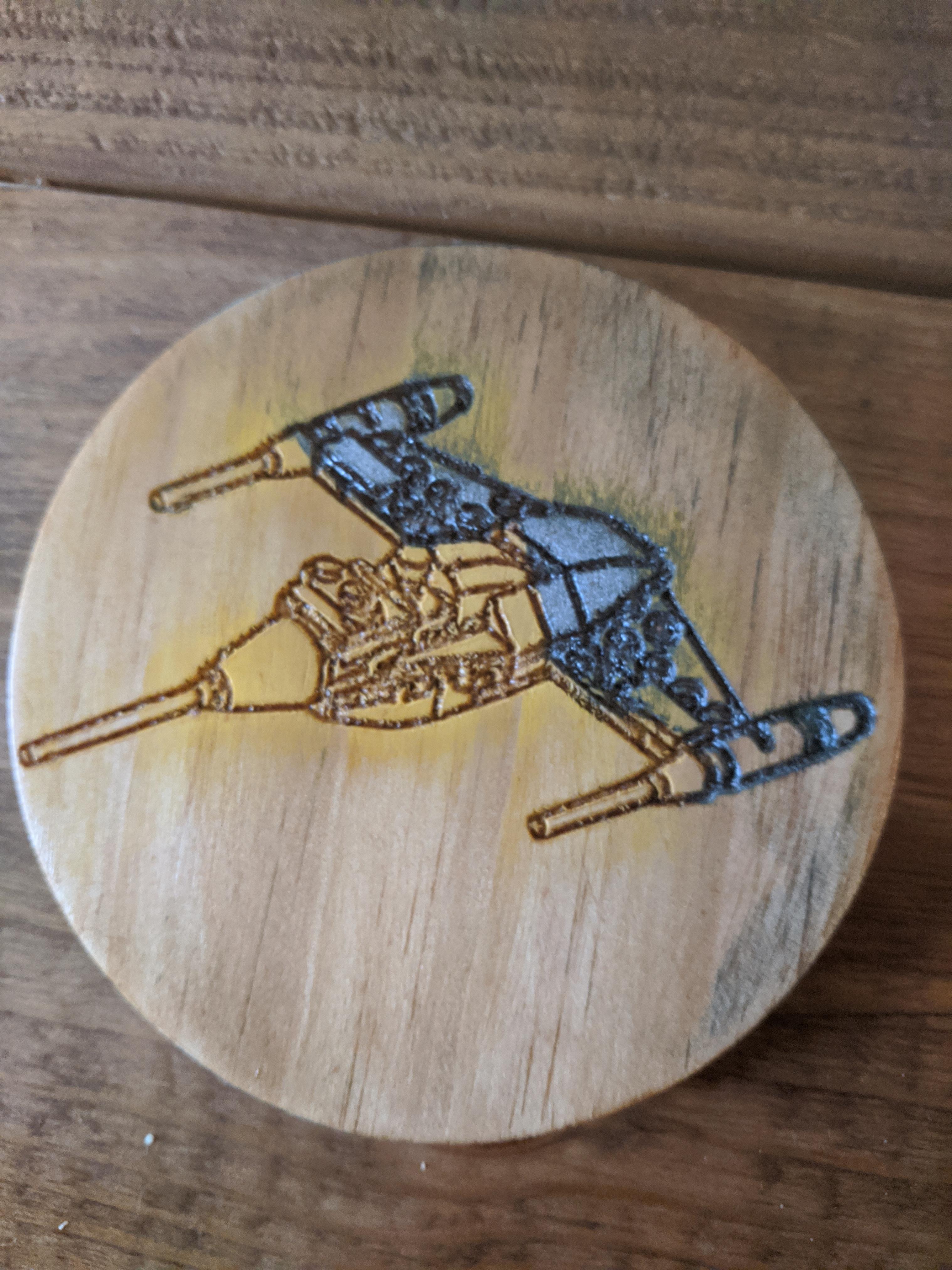
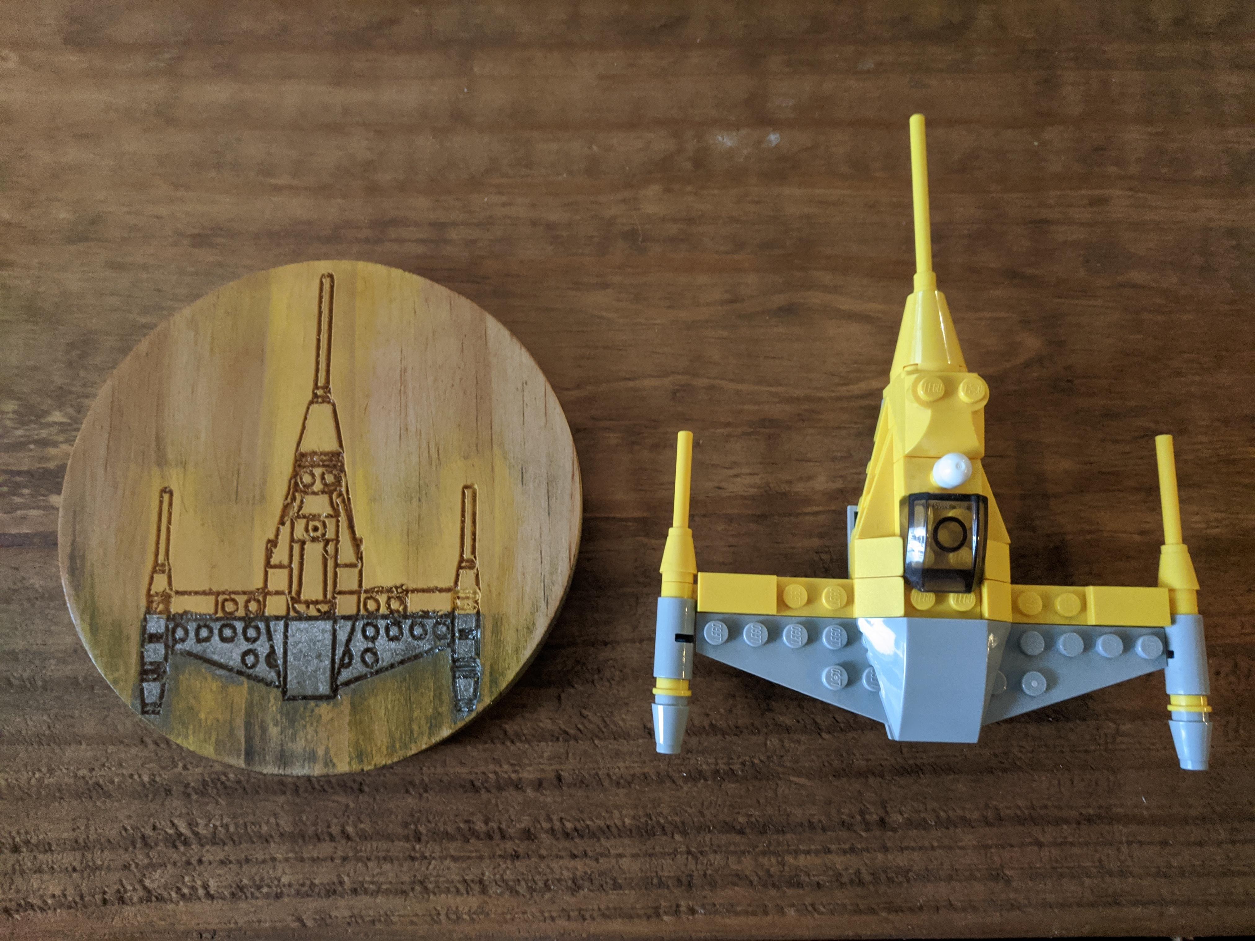
I think the most important part of a project is learning from your mistakes. But even more importantly, giving yourself the opportunity to make mistakes because you're going to learn a lot from that process.
For instance, I carved these coasters partially to test quick and easy paint schemes. I didn't like how half of them came out, but I thought of a new way to produce these. Rather than tape the areas post cut, I covered my raw material with painters tape before sending it through the CNC machine. The tape along the cut lines is removed with the material, covering the rest of the board. This made post processing easier and I got better results.
I also didn't like the 5 inch diameter - it was fine for the full builds, but the assemblies are way more interesting in my opinion. To show them off properly, I needed a larger space, which is how I decided to use the full board.
Even with all the mistakes, I liked two of them, and they work well at holding our fruity girly drinks!
To carve then cut out, I started with my 60 degree V-bit for the detail work. Once done, I swapped out the bit to a 1/8 straight cut bit. In Easel, I used shapes to create a circle outline around the first carvings, then removed the ship SVGs. When cutting out things on a router, use tabs. These are thin sections of wood that help hold the cutout in place. You can easily separate and sand these once the machine is finished.