Ledboard Pi
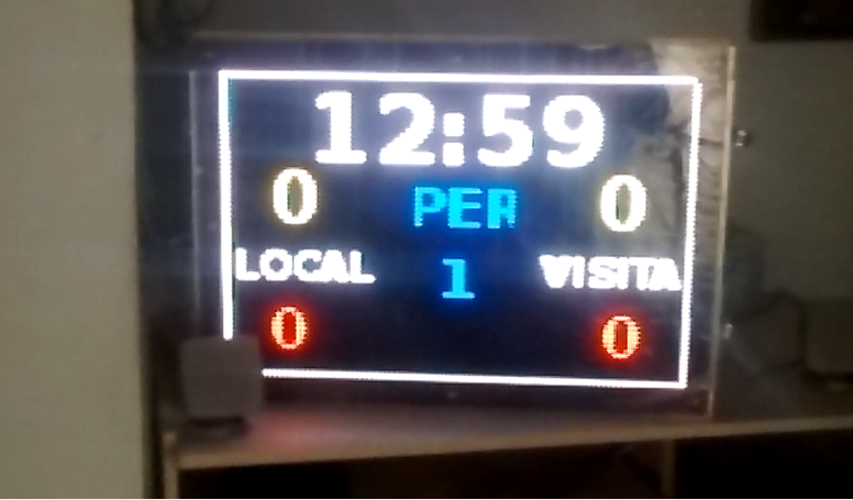
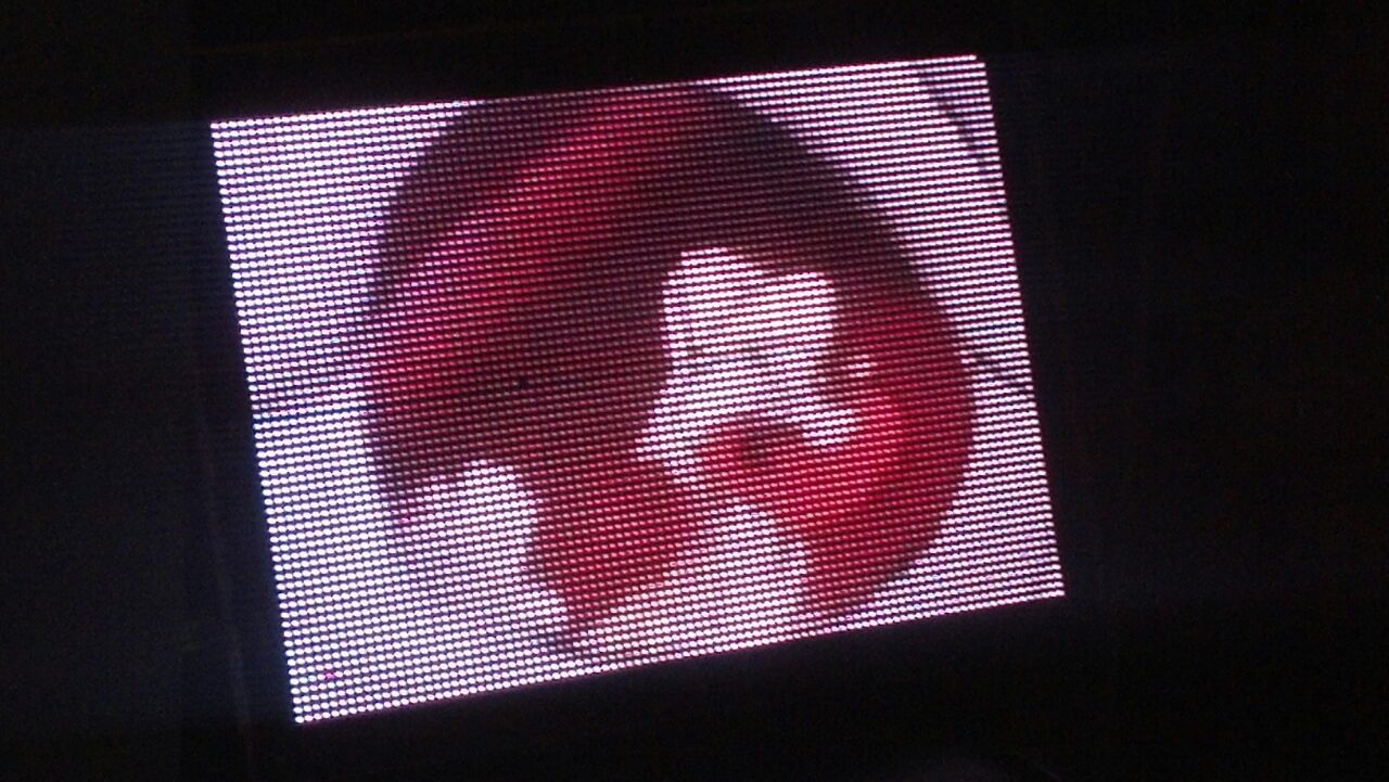
Ledboard Pi screen is the result of years of experiences, learning, and development; but also, the result of have the right tools (hardware, software, firmware) in this right moment: Raspberry Pi 4 (with Raspberry Pi 3 works too) with its speed, memory and wireless capaility, the marvelous project Raspberry Pi LED Matrix Display based on the rpi-rgb-led-matrix and rpi-fb-matrix libraries (for driving many commercial RGB LED Panels through GPIO) to show the Raspberry Pi's video output on a large RGB LED matrix display (for this instructable, the resolution is 96x64 using 6 sparkfun 32x32 panels). All these is controlled with a GUI application programmed using lazarus ide on a very light openbox desktop installed over a Raspbian Buster Lite image and finally, show a whatever your imagination can programming: a Multi-Sport Scoreboard, a Digital Signage, or a Video Player; there are no limits. This project, controlled by any computer, capable to run VNC Viewer, because the VNC Server is also installed on Raspberry Pi 4's Rasbian Buster Lite.
From tomorrow, I will try to explain in detail every step to get this project work.
Supplies
We need for this project:
Hardware
- One Raspberry Pi 3 or better, Raspberry Pi 4 with its 5V 2.5 A power supply
- One Electrodragon RGB LED Matrix Panel Drive Board For Raspberry Pi
- Six 32x32 RGB LED Panel from Sparkfun
- One 40A 5v Power Supply
- One 3 meters Aluminum rectangular frame 82.5 mm x 38 mm
- One cut of acrylic size W 576 mm x H 384 mm
- One cut of polarized film
Software
- hezeller rpi-rgb-led-matrix library
- Adafruit rpi-fb-matrix library
- Raspbian buster lite or realtimepi-buster-lite images
- Openbox
- For control pc/laptop/Raspberry Pi 3 or 4, Real VNC Viewer for Windows or Linux or Raspbian
- Lazarus IDE for raspbian buster lite
- Leboard Pi application
to be continued...
Setting Raspberry Pi 3/4 OS Stuff
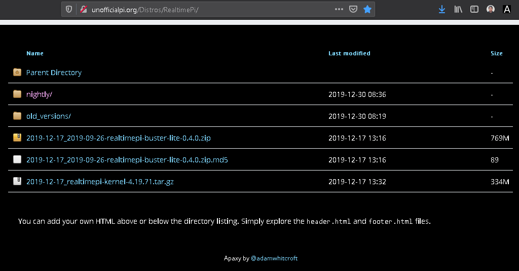
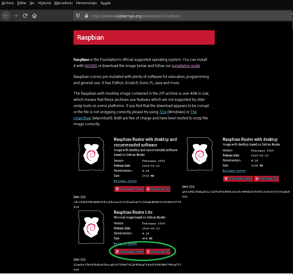
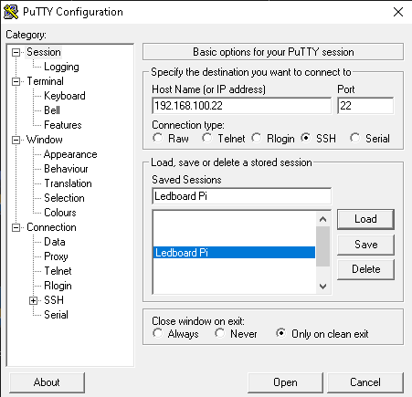
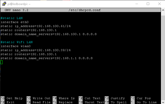
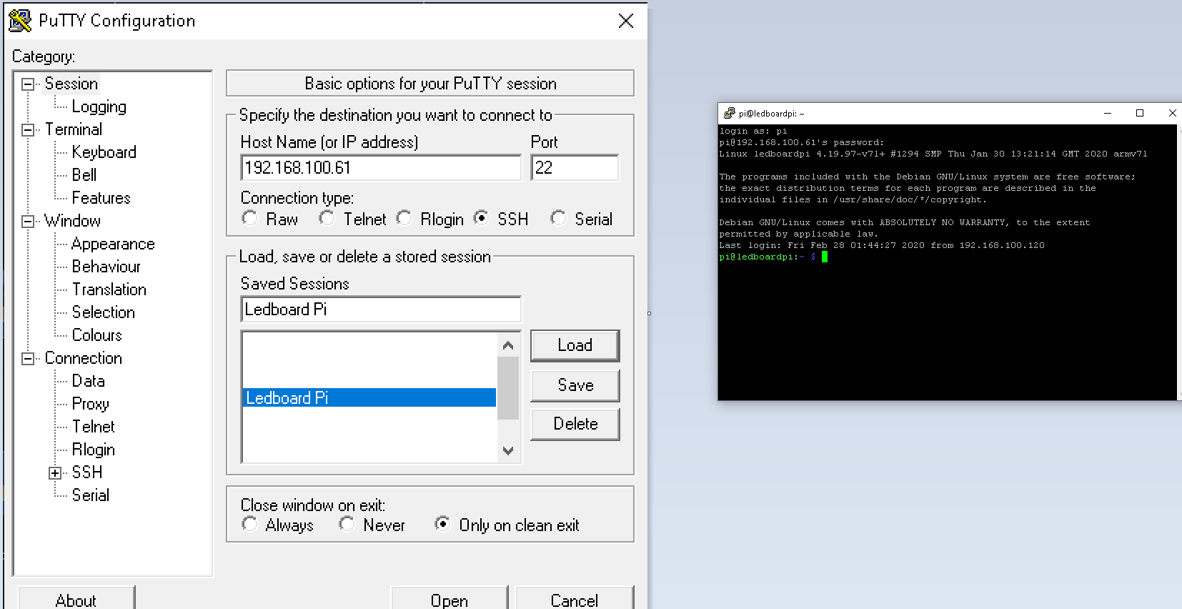
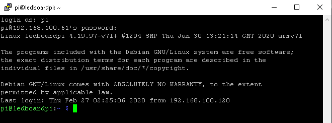
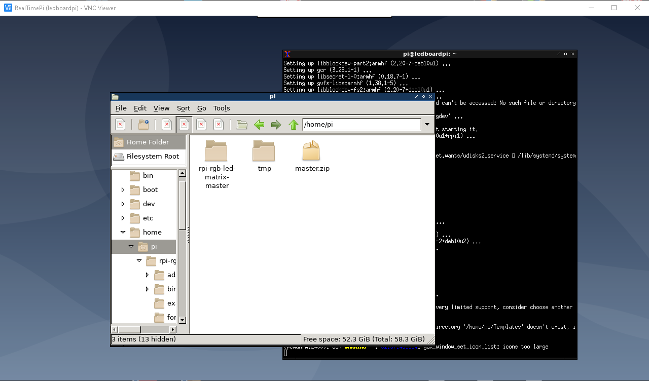
Once we have the Hardware parts, we need to get the OS stuff:
First, we must get the OS for Raspbian 3/4. in my case, I decide to use realtime buster lite; but you can use also Raspbian Buster Lite version. Then you need to transfer this image into micro SD card using balenaEtcher.
Then, we need to connect a HDMI display and an usb keyboard and a cat5 network cable connected to
Raspberry Pi 3/4 RJ45; so, we can search the Raspberry Pi 3/4 IP for make the initial setup: network IP, wired and wireless. I used the advanced ip scanner. Now, through raspi-config, activate the SSH Server for connect remotly using Putty for complete the rest of the Ledboard Pi setup.
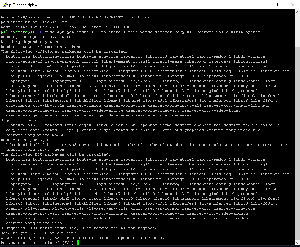
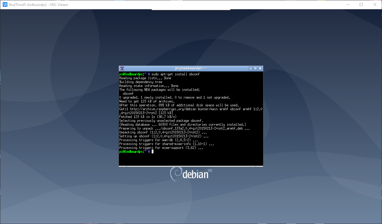
Now, over the lite version, we are going to install a light desktop environment with openbox
sudo apt-get install --no-install-recommends xserver-xorg x11-xserver-utils xinit openbox
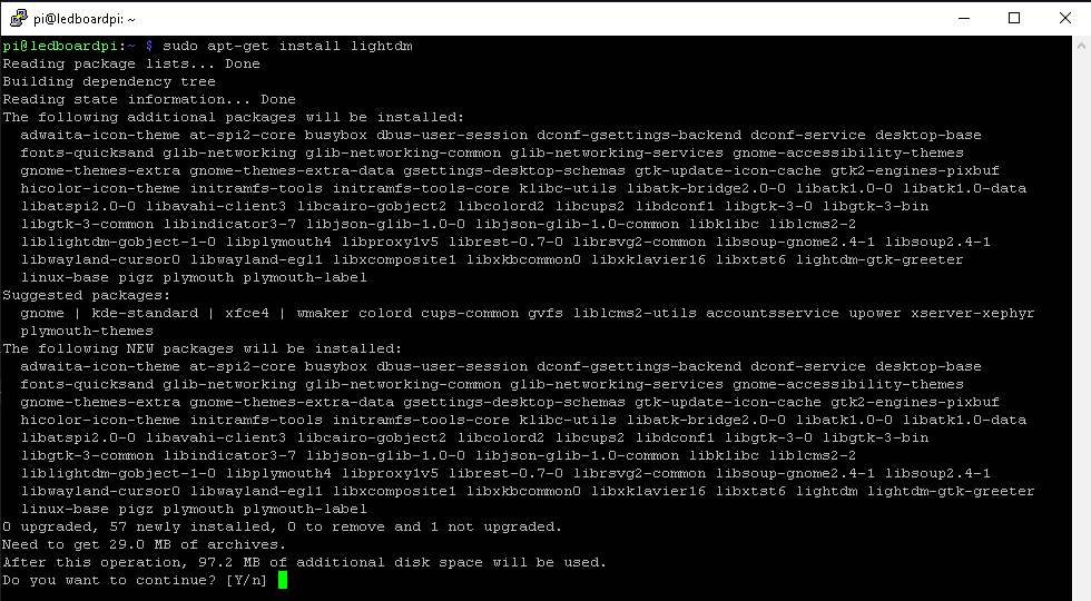
- Then, install lightdm (Login manager)
sudo apt-get install lightdm
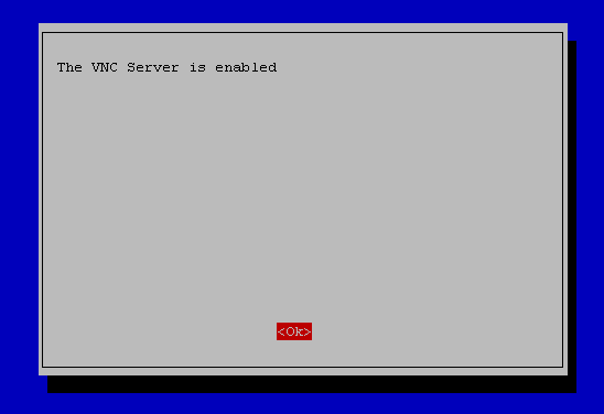
- Activate realvncserver from raspi-config
sudo raspi-config > Interface options > vncserver > activate vncserver
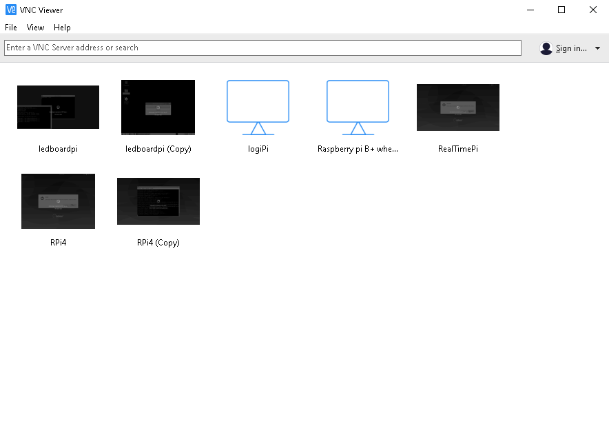
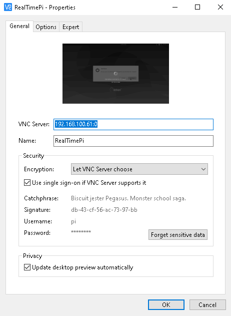
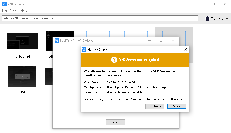
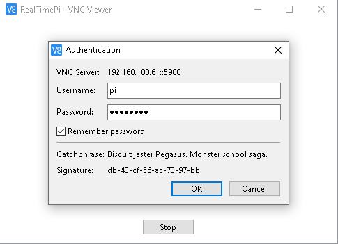
- Here, once the vnceserver is activated, we are going to use VNC Viewer. In this, the desktop to configure in the connection is 0, ex. If IP is 192.168.100.61, the connection is "192.168.100.61:0".
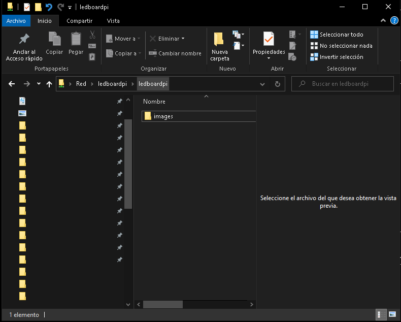
- We need a link between the control computer/laptop and the Ledboard Pi, so samba need to be installed for transfering of source code, files, pictures, videos, etc.
sudo apt-get install samba samba-common-bin -y
- Make sure your user is the owner of the path you are trying to share via Samba
sudo chown -R pi:pi /home/pi/share
- Take a copy of the original samba share file
sudo cp /etc/samba/smb.conf /etc/samba/smb.bak
- Edit the samba configuration file
sudo nano /etc/samba/smb.conf
- Leave workgroup as WORKGROUP (or name it as You wish)
#wins support = no
to
wins support = yes
Then ....
#This is the name of the share folder it will show up as when you browse
[ledboardpi]
comment = ledboardPi share folder
path = /home/pi/Share
create mask = 0775
directory mask = 0775
read only = no
browseable = yes
public = yes
force user = pi
only guest = no
Now, we can access "home/pi/share" folder in /home/pi path from other computer.
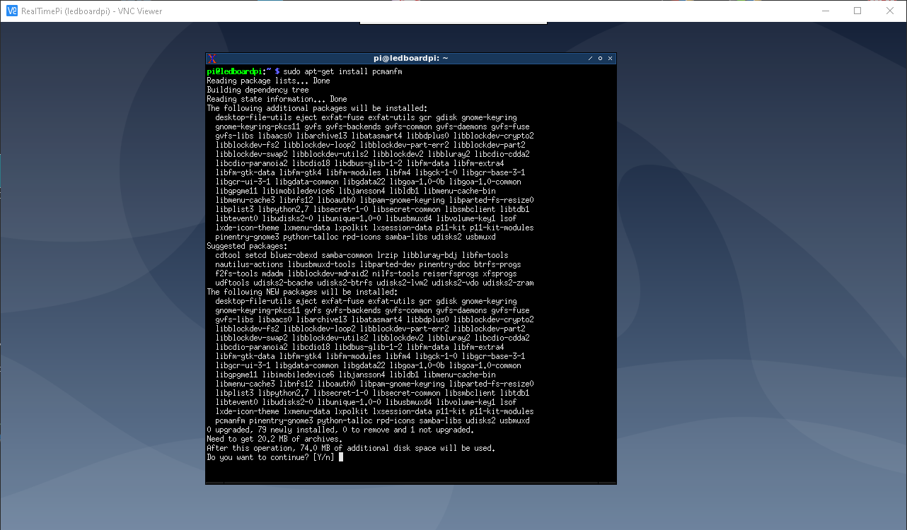
For manage the file system using a gui app, we going to install pcmanfm
sudo apt-get install pcmanfm
Download, Setup, and Running of RGB LED Panel Needed Libraries
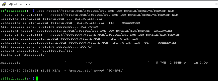
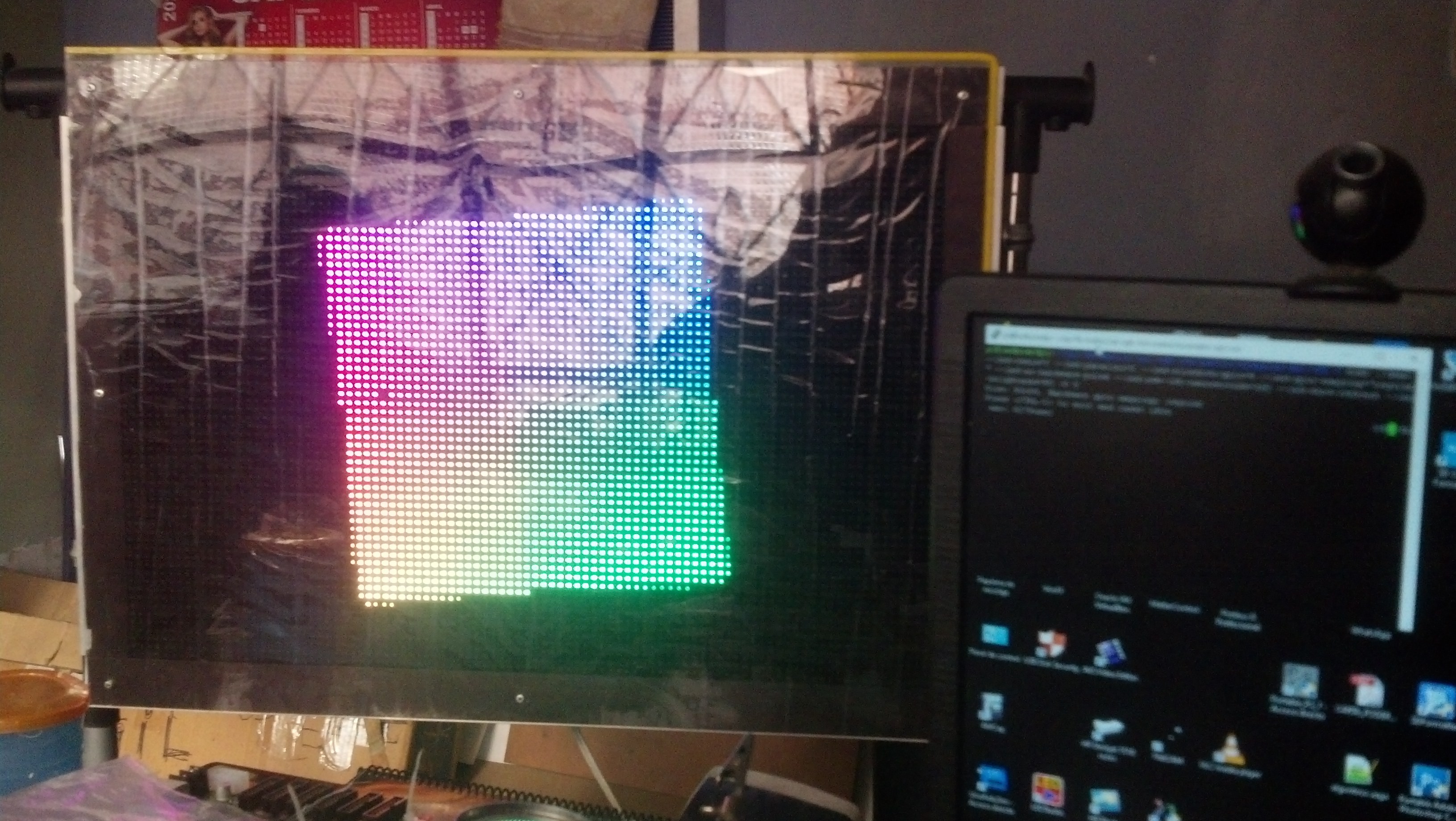
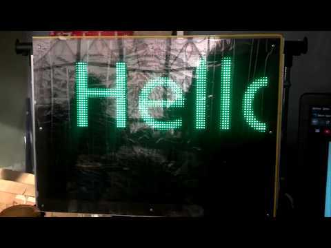
First, install pre-requisites
sudo apt-get update

sudo apt-get install -y build-essential git libconfig++-dev
sudo apt-get install libgraphicsmagick++-dev libwebp-dev -y
sudo apt-get install python2.7-dev python-pillow -y
- Then, download and compile hzeller rpi-rgb-led-matrix
wget https://github.com/hzeller/rpi-rgb-led-matrix/archive/master.zip
unzip master.zip
cd rpi-rgb-led-matrix-master/ && make
- Also, download and Install rpi-fb-matrix
You must clone this repository with the recursive option so that necessary submodules are also cloned. Run this command:
git clone --recursive  https://github.com/adafruit/rpi-fb-matrix.git
make
Note: replace the rpi-rgb-led-matrix library downloaded early into the rpi-fb-matrix folder
- Now, we are going to test those libraries, remember, rpi-fb-matrix depends on rpi-rgb-led-matrix.
cd rpi-fb-matrix
cd rpi-rgb-led-matrix
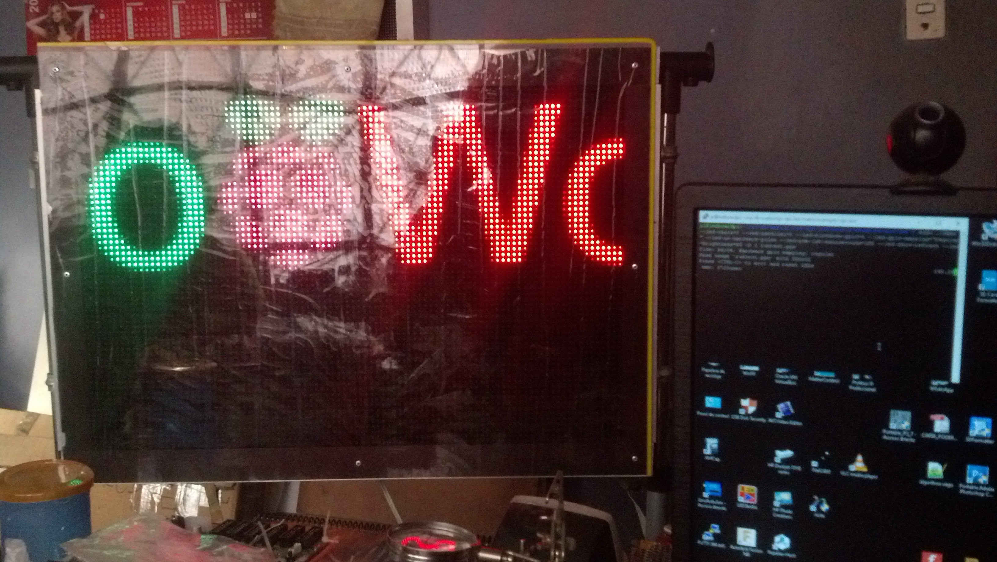
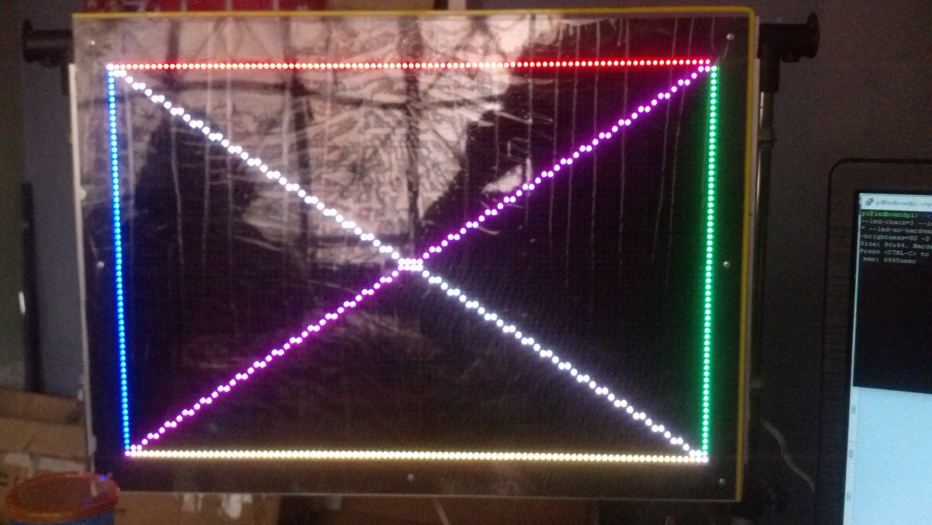
sudo ./demo --led-chain=3 --led-parallel=2 --led-slowdown-gpio=4 --led-gpio-mapping="regular" --led-no-hardware-pulse --led-pwm-lsb-nanoseconds=180 --led-show-refresh --led-brightness=80 -D 0
sudo ./demo --led-chain=3 --led-parallel=2 --led-slowdown-gpio=4 --led-gpio-mapping="regular" --led-no-hardware-pulse --led-pwm-lsb-nanoseconds=180 --led-show-refresh --led-brightness=80 -D 1 runtext.ppm
sudo ./demo --led-chain=3 --led-parallel=2 --led-slowdown-gpio=4 --led-gpio-mapping="regular" --led-no-hardware-pulse --led-pwm-lsb-nanoseconds=180 --led-show-refresh --led-brightness=80 -D 2 runtext.ppm
sudo ./demo --led-chain=3 --led-parallel=2 --led-slowdown-gpio=4 --led-gpio-mapping="regular" --led-no-hardware-pulse --led-pwm-lsb-nanoseconds=180 --led-show-refresh --led-brightness=80 -D 3
sudo ./demo --led-chain=3 --led-parallel=2 --led-slowdown-gpio=4 --led-gpio-mapping="regular" --led-no-hardware-pulse --led-pwm-lsb-nanoseconds=180 --led-show-refresh --led-brightness=80 -D 4
sudo ./demo --led-chain=3 --led-parallel=2 --led-slowdown-gpio=4 --led-gpio-mapping="regular" --led-no-hardware-pulse --led-pwm-lsb-nanoseconds=180 --led-show-refresh --led-brightness=80 -D 5
sudo ./demo --led-chain=3 --led-parallel=2 --led-slowdown-gpio=4 --led-gpio-mapping="regular" --led-no-hardware-pulse --led-pwm-lsb-nanoseconds=180 --led-show-refresh --led-brightness=80 -D 6
sudo ./demo --led-chain=3 --led-parallel=2 --led-slowdown-gpio=4 --led-gpio-mapping="regular" --led-no-hardware-pulse --led-pwm-lsb-nanoseconds=180 --led-show-refresh --led-brightness=80 -D 7
sudo ./demo --led-chain=3 --led-parallel=2 --led-slowdown-gpio=4 --led-gpio-mapping="regular" --led-no-hardware-pulse --led-pwm-lsb-nanoseconds=180 --led-show-refresh --led-brightness=80 -D 8
sudo ./demo --led-chain=3 --led-parallel=2 --led-slowdown-gpio=4 --led-gpio-mapping="regular" --led-no-hardware-pulse --led-pwm-lsb-nanoseconds=180 --led-show-refresh --led-brightness=80 -D 9
sudo ./demo --led-chain=3 --led-parallel=2 --led-slowdown-gpio=4 --led-gpio-mapping="regular" --led-no-hardware-pulse --led-pwm-lsb-nanoseconds=180 --led-show-refresh --led-brightness=80 -D 10
sudo ./demo --led-chain=3 --led-parallel=2 --led-slowdown-gpio=4 --led-gpio-mapping="regular" --led-no-hardware-pulse --led-pwm-lsb-nanoseconds=180 --led-show-refresh --led-brightness=80 -D 11<br>
All run fine.
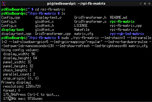
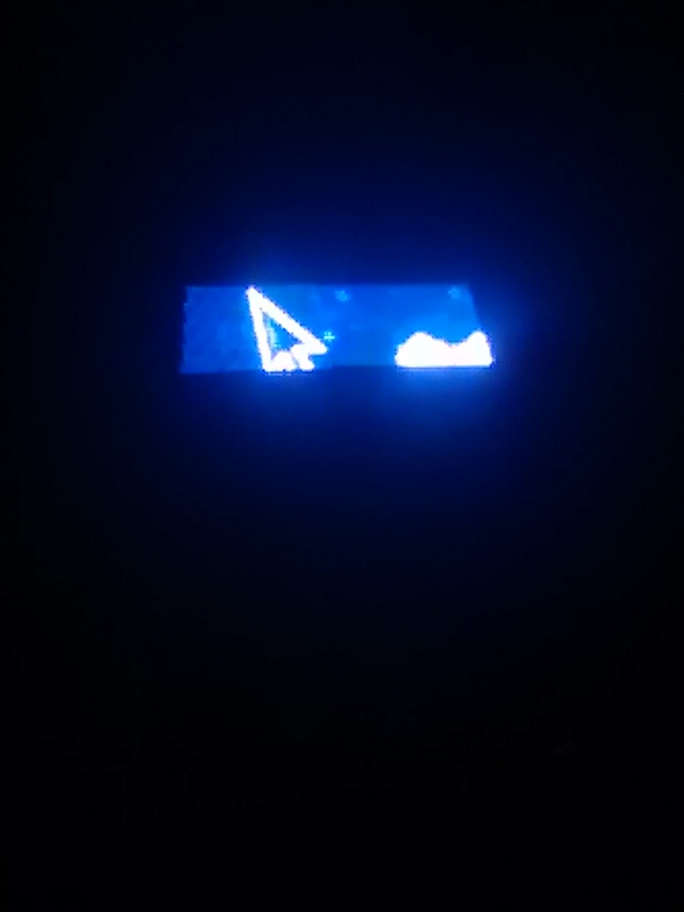
- Now, the rpi-fb-matrix library. This will show a portion (96x64) of screen into RGB LED Panels based Ledboard Pi
cd /home/pi/rpi-fb-matrix
REMEMBER, copy the last version of rpi-rgb-led-matrix library into the rpi-fb-matrix folder. VERY IMPORTANT
make clean
make all
Those last commands, for both rpi-fb-matrix and rpi-rgb-led-matrix libraries.....
For the rpi-fb-matrix is necessary a correct configuration of matrix.cfg ( I renamed davenew.cfg for this instructable), read, analyze for custom projects with different number of RGB LED Panels...
LED Matrix Display Configuration<br>
// Define the entire width and height of the display in pixels.
// This is the _total_ width and height of the rectangle defined by all the
// chained panels.  The width should be a multiple of the panel pixel width (32),
// and the height should be a multiple of the panel pixel height (8, 16, or 32).
display_width = 96;
display_height = 64;


// Define the width of each panel in pixels.  This should always be 32 (but can
// in theory be changed).
panel_width = 32;


// Define the height of each panel in pixels.  This is typically 8, 16, or 32.
// NOTE: Each panel in the display _must_ be the same height!  You cannot mix
// 16 and 32 pixel high panels for example.
panel_height = 32;


// Define the total number of panels in each chain.  Count up however many
// panels are connected together and put that value here.  If you're using
// multiple parallel chains count each one up separately and pick the largest
// value for this configuration.
chain_length = 3;


// Define the total number of parallel chains.  If using the Adafruit HAT you
// can only have one chain so stick with the value 1.  The Pi 2 can support up
// to 3 parallel chains, see the rpi-rgb-led-matrix library for more information:
// https://github.com/hzeller/rpi-rgb-led-matrix#chaining-parallel-chains-and-coordinate-system
parallel_count = 2;


// Configure each LED matrix panel.
// This is a two-dimensional array with an entry for each panel.  The array
// defines the grid that will subdivide the display, so for example a 64x64 size
// display with 32x32 pixel panels would be a 2x2 array of panel configurations.
//
// For each panel you must set the order that it is within its chain, i.e. the
// first panel in a chain is order = 0, the next one is order = 1, etc.  You can
// also set a rotation for each panel to account for changes in panel orientation
// (like when 'snaking' a series of panels end to end for shorter wire runs).
//
// For example the configuration below defines this grid display of panels and
// their wiring (starting from the upper right panel and snaking left, down, and
// right to the bottom right panel):
//       ______________    ______________    ______________
//      |    Panel     |  |    Panel     |  |    Panel     |
//      | order  = 2   |<=| order  = 1   |<=| order  = 0   |<= Chain 1 (from Pi)
//      | rotate = 0   |  | rotate = 0   |  | rotate = 0   |
//      |______________|  |______________|  |______________|
//       ______________    ______________    ______________
//      |    Panel     |  |    Panel     |  |    Panel     |
//      | order  = 2   |<=| order  = 1   |<=| order  = 0   |<= Chain 2 (from Pi)
//      | rotate = 0   |  | rotate = 0   |  | rotate = 0   |
//      |______________|  |______________|  |______________|
//
// Notice the chain starts in the upper right and snakes around to the bottom
// right.  The order of each panel is set as its position along the chain,
// and rotation is applied to the lower panels that are flipped around relative
// to the panels above them.
//
// Not shown but if you're using parallel chains you can specify for each entry
// in the panels list a 'parallel = x;' option where x is the ID of a parallel
// chain (0, 1, or 2).
panels = ( ( { order = 2; rotate = 0; parallel=0; }, { order = 1; rotate = 0; parallel=0;} , { order = 0; rotate = 0; parallel=0;},
         { order = 2; rotate = 0; parallel=1; }, { order = 1; rotate = 0; parallel=1;} , { order = 0; rotate = 0; parallel=1;} )
)

// By default the rpi-fb-matrix tool will resize and scale down the screen
// to fit the resolution of the display panels.  However you can instead grab
// a specific pixel-perfect copy of a region of the screen by setting the x, y
// screen pixel coordinates below.  A rectangle of the exact size of the display
// (i.e. display_width x display_height pixels) will be copied from the screen
// starting at the provided x, y coordinates.  Comment this out to disable
// this crop behavior and instead resize the screen down to the matrix display.
crop_origin = (0, 0)
Compiling, Setting and Test Ledboard Pi GUI Application
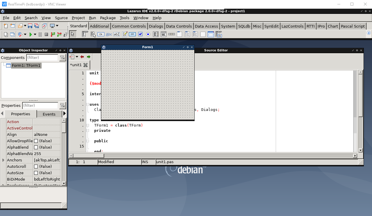
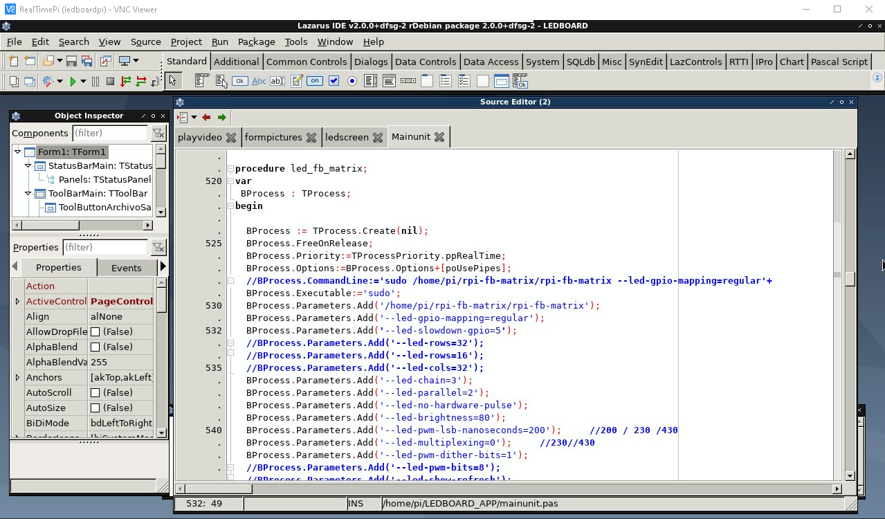
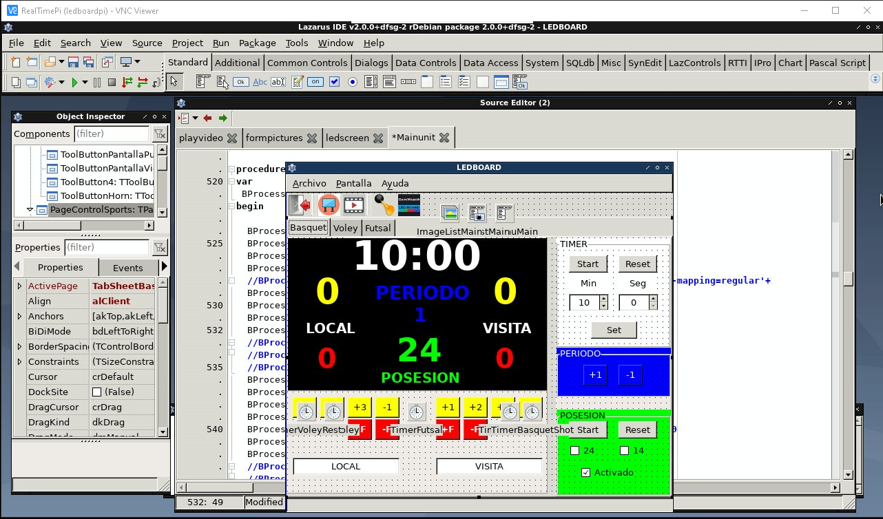
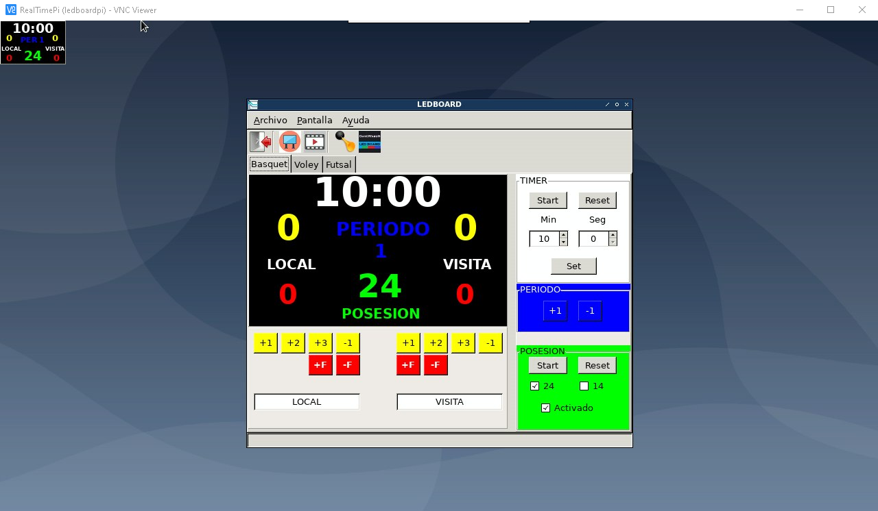
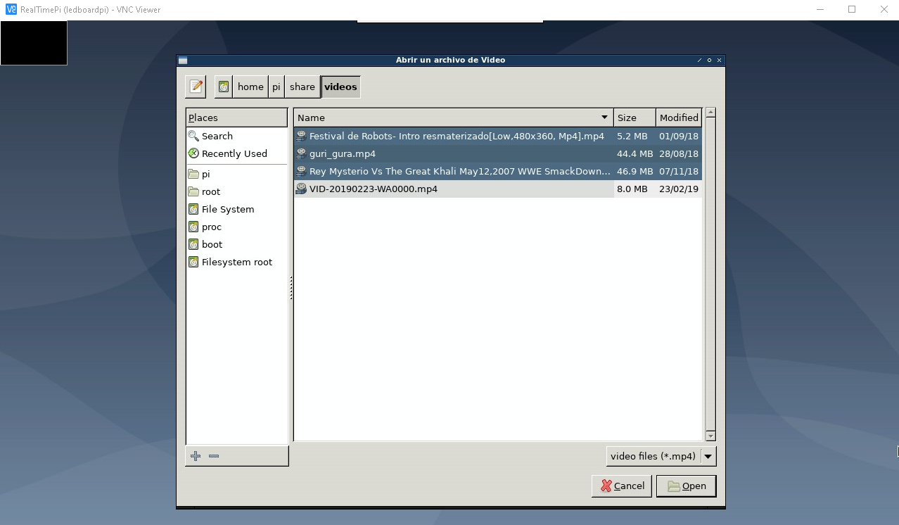
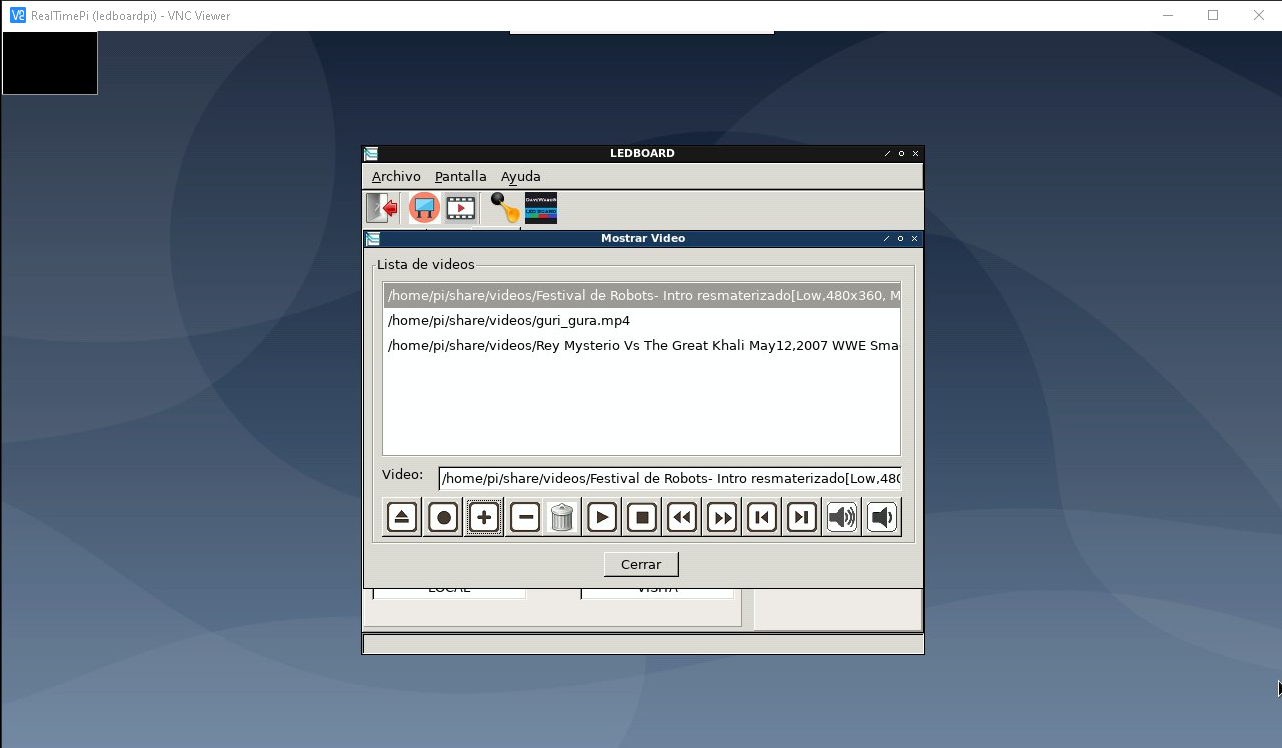
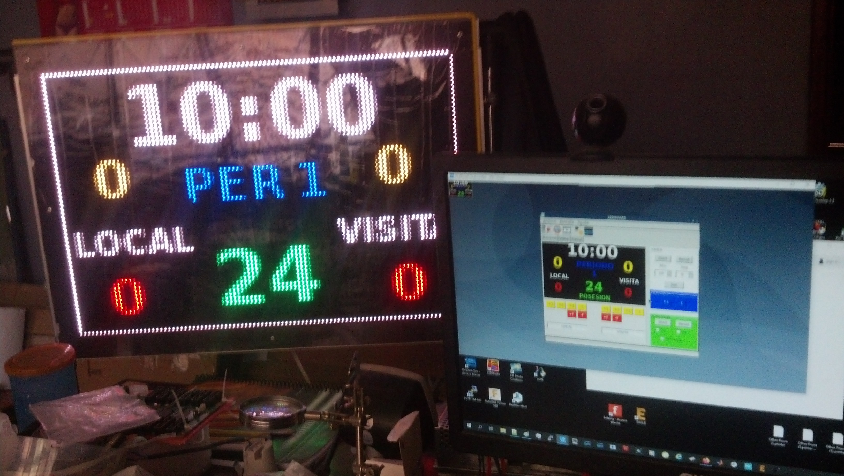
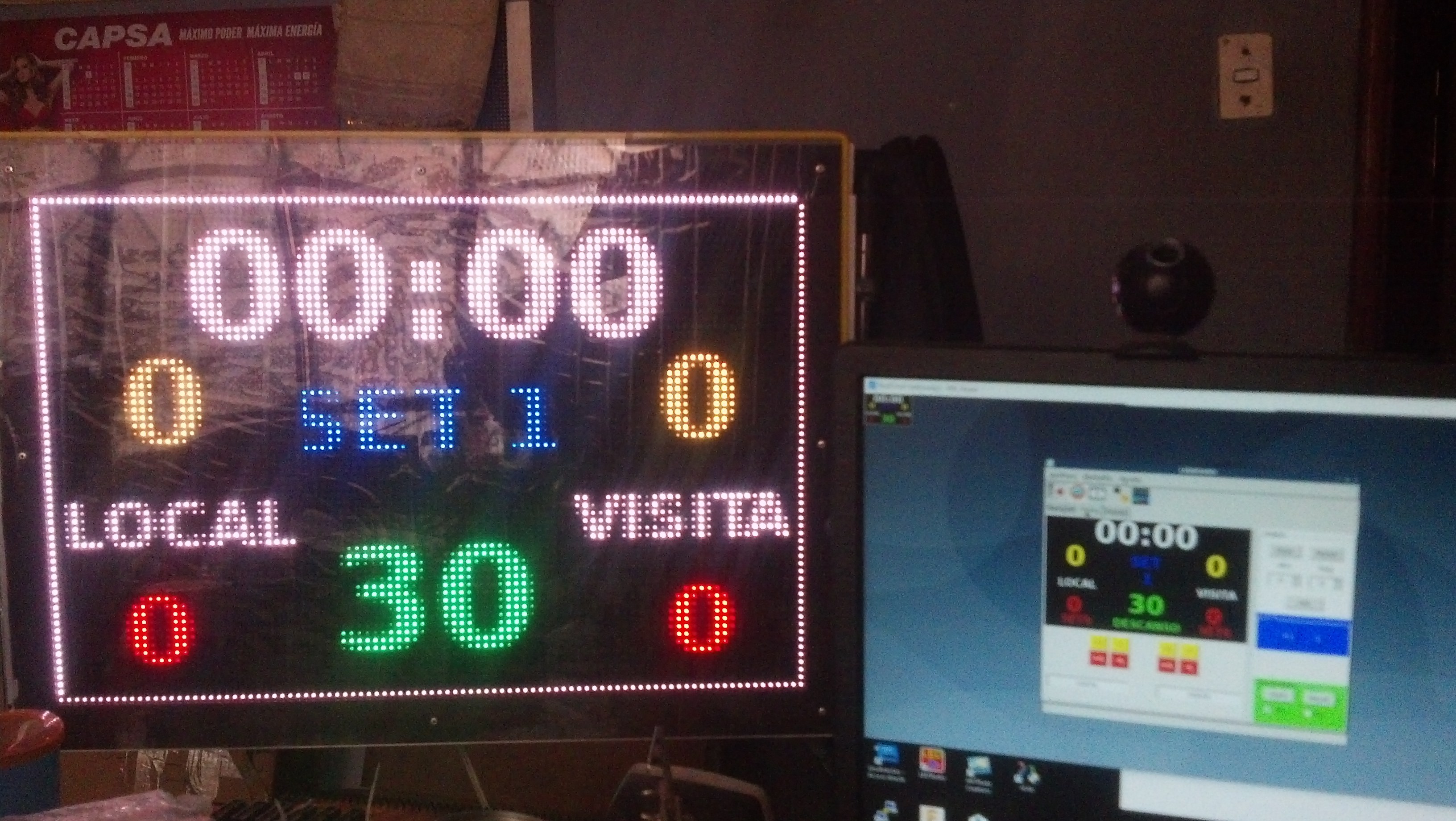
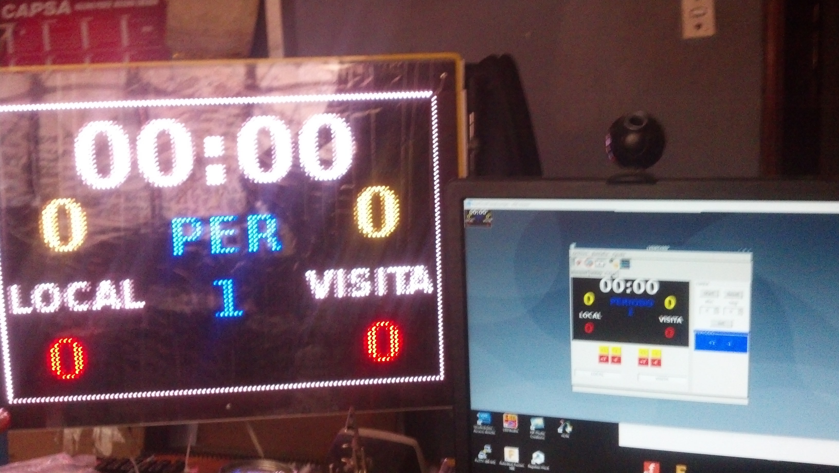
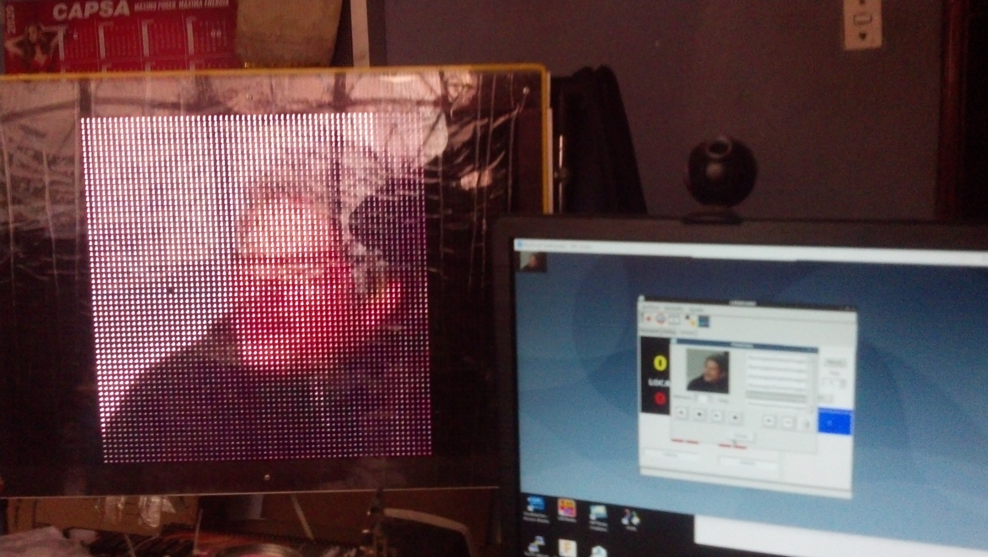
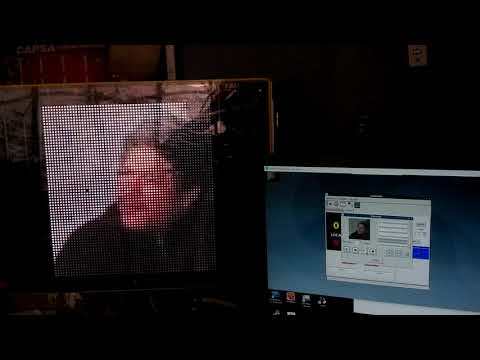
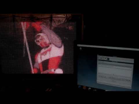
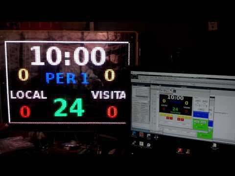
- We need a programming IDE to create a GUI application (Ledboard Pi). Then, I choose "Lazarus IDE" very similar to Delphi/C++ Builder I used within Windows OS.
sudo apt-get install lazarus-ide
- Once installed, just execute:
lazarus-ide
- Opening Ledboard Pi project, then compile to get the Ledboard Pi Application. Before open this application, make a directory named LEDBOARD_APP in the path /home/pi, then copy the Ledboard Pi application to this.
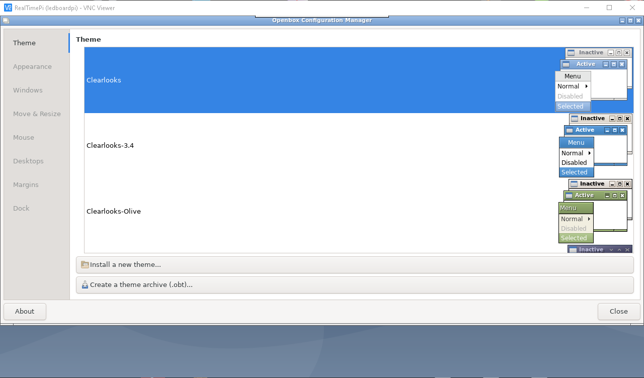
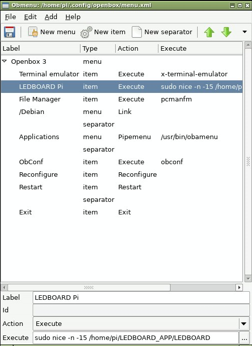
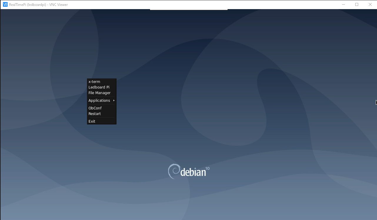
- Now, we are going to add a link into the right-click menu of the openbox. How, we need the obmenu, also xterm using Putty link, so:
sudo apt-get install obmenu xterm
- Now, we can use the terminal and obmenu within vncviewer window:
- Call xterm from right-click menu
- Open obmenu from xterm
- Add new item: Ledboard Pi
- Choose New item
- name it Ledboard Pi
- execute sudo nice -n -15 /home/pi/LEDBOARD_APP/LEDBOARD
- Download the "horn.WAV", then, using network linked samba location "\\ledboardpi\ledboardpi\" copy this and rename it into realtimePi environment as "horn.wav". This file, once renamed, must be copied to /home/pi folder.
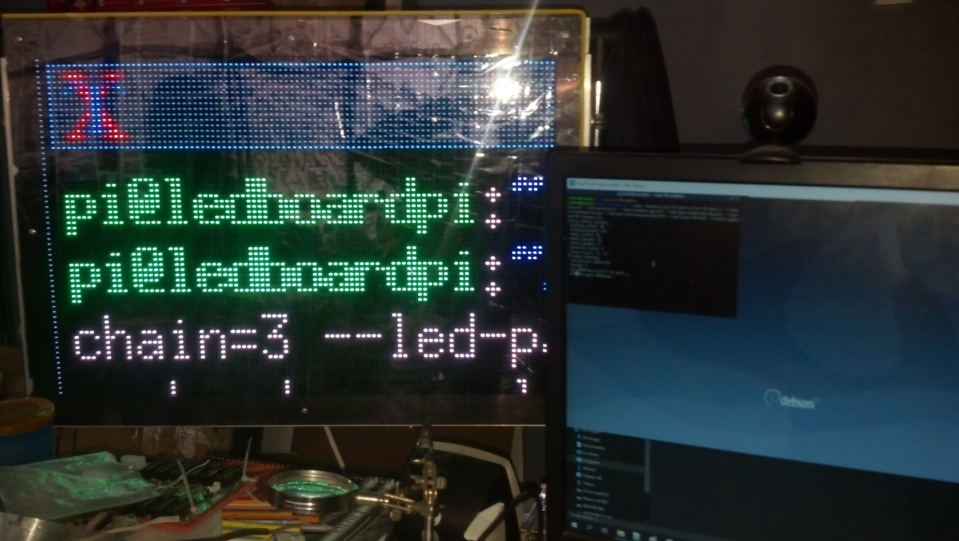
- Done, you must be able to run Ledboard Pi as well as You see in videos and pictures.
Install and Setup of the WiFi Hotspot
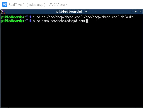


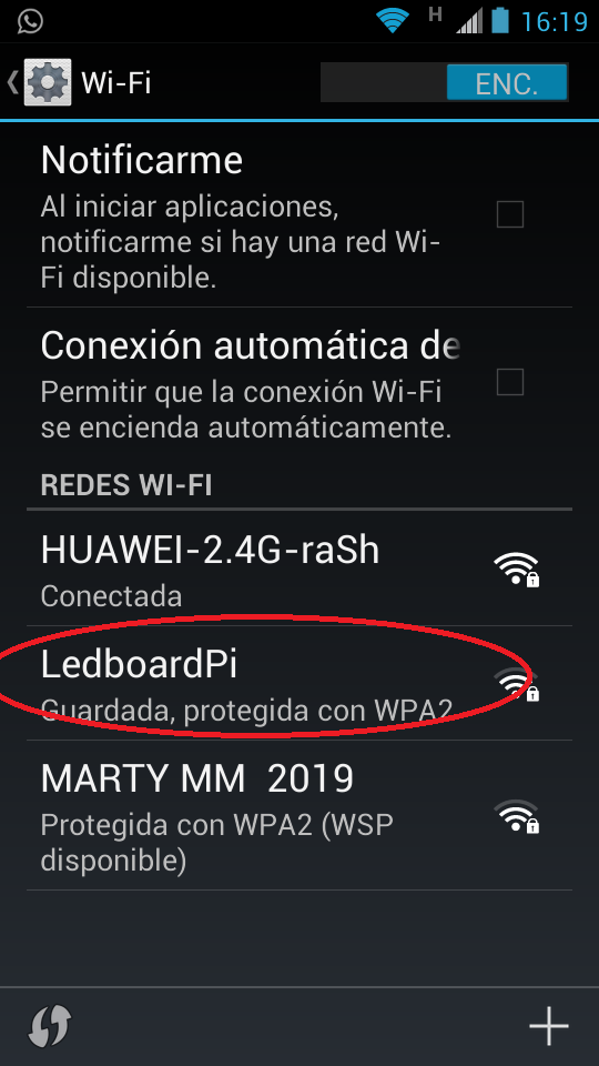
This project was designed to run using realvnc viewer from a laptop connected wirelessly to the Raspberry Pi 3/4. So, this is the final step to get it run, and say "hasta la vista baby" to the wired nightmare.
Software Setup
sudo apt-get update
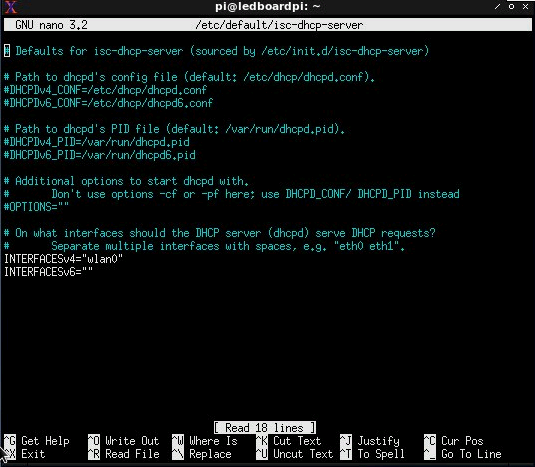
sudo apt-get install hostapd isc-dhcp-server
DHCP Server
- Be wise and always make a backup of the default config
sudo cp /etc/dhcp/dhcpd.conf /etc/dhcp/dhcpd.conf.default
- Edit the defult config file
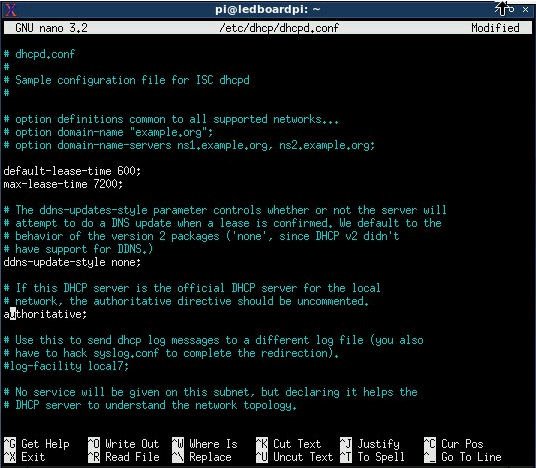
sudo nano /etc/dhcp/dhcpd.conf
- Comment the following lines...
option domain-name "example.org";
option domain-name-servers ns1.example.org, ns2.example.org;
- to read:
#option domain-name "example.org";
#option domain-name-servers ns1.example.org, ns2.example.org;
- ...and un-comment this line
#authoritative;
- ... to read:
authoritative;
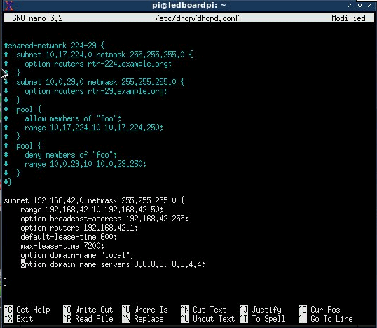
- ... scroll down at the bottom of the file and write the following lines:
subnet 192.168.42.0 netmask 255.255.255.0 {
	range 192.168.42.10 192.168.42.50;
	option broadcast-address 192.168.42.255;
	option routers 192.168.42.1;
	default-lease-time 600;
	max-lease-time 7200;
	option domain-name "local";
	option domain-name-servers 8.8.8.8, 8.8.4.4;
}
Let’s setup wlan0 for static IP
- First, shut it down...
sudo ifdown wlan0
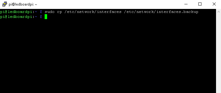
- ...keep it safe and make a backup file:
sudo cp /etc/network/interfaces /etc/network/interfaces.backup
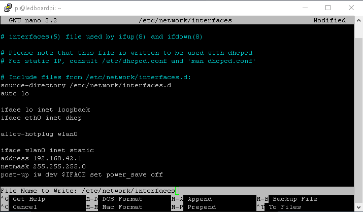
- ...edit the network interfaces file:
sudo nano /etc/network/interfaces
- ... edit accordingly to read:
source-directory /etc/network/interfaces.d

auto lo

iface lo inet loopback
iface eth0 inet dhcp

allow-hotplug wlan0

iface wlan0 inet static
address 192.168.42.1
netmask 255.255.255.0
post-up iw dev $IFACE set power_save off
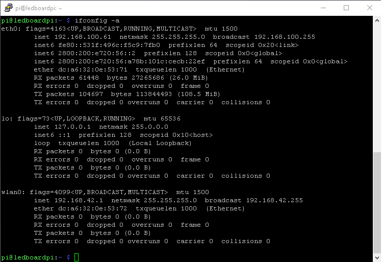
- ...close the file and assign a static IP now
sudo ifconfig wlan0 192.168.42.1
Done...
Hostapd
- Create a file and edit it:
sudo nano /etc/hostapd/hostapd.conf
- Modify ssid with a name of your choice and wpa_passphrase to a WiFi authen
interface=wlan0
ssid=LedboardPi
hw_mode=g
channel=6
macaddr_acl=0
auth_algs=1
ignore_broadcast_ssid=0
wpa=2
wpa_passphrase=davewarePi
wpa_key_mgmt=WPA-PSK
wpa_pairwise=TKIP
rsn_pairwise=CCMP
Let’s configure the network address translation
- Create a backup file
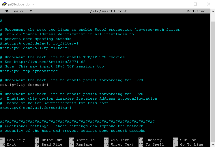
sudo cp /etc/sysctl.conf /etc/sysctl.conf.backup
- edit the config file
sudo nano /etc/sysctl.conf
- ...un-comment or add to the bottom:
net.ipv4.ip_forward=1
- # ...and activate it immediately:
sudo sh -c "echo 1 > /proc/sys/net/ipv4/ip_forward"
- ...modify the iptables to create a network translation between eth0 and the wifi port wlan0
sudo iptables -t nat -A POSTROUTING -o eth0 -j MASQUERADE
sudo iptables -A FORWARD -i eth0 -o wlan0 -m state --state RELATED,ESTABLISHED -j ACCEPT
sudo iptables -A FORWARD -i wlan0 -o eth0 -j ACCEPT
- ...make this happen on reboot by runnig
sudo sh -c "iptables-save > /etc/iptables.ipv4.nat"
- ...and editing again
sudo nano /etc/network/interfaces
- ...appending at then end:
up iptables-restore < /etc/iptables.ipv4.nat
- Our /etc/network/interfaces file will now look like this:
source-directory /etc/network/interfaces.d
auto lo

iface lo inet loopback

allow-hotplug eth0

iface eth0 inet static
address 192.168.100.61
netmask 255.255.255.0
gateway 192.168.100.1

allow-hotplug wlan0

iface wlan0 inet static
address 192.168.42.1
netmask 255.255.255.0
network 192.168.42.0
broadcast 192.168.42.255

source-directory /etc/network/interfaces.d
Let’s test our access point by running:
sudo /usr/sbin/hostapd /etc/hostapd/hostapd.conf
- Your hotspot is up and running: try to connect to it from a computer or a smartphone. When you do so, you should also see some log activity on your terminal. If you're satisfied, stop it with CTRL+C
- Let's clean everything: sudo service hostapd start sudo service isc-dhcp-server start
- ...and make sure that we're up and running:
sudo service hostapd status
sudo service isc-dhcp-server status
- ...let's configure our daemons to start at boot time:
sudo update-rc.d hostapd enable
sudo update-rc.d isc-dhcp-server enable

sudo systemctl unmask hostapd
sudo systemctl unmask isc-dhcp-server
- ...reboot the pi.
sudo reboot
You should now be able to see your pi WiFi, connect to it and access internet to it. As a quick comparison, streaming 4k videos will consume about 10% of the pi CPU so… use it accordingly.
As a bonus, if you want to check what’s happening on your WiFi hotspot, check the log file:
tail -f /var/log/syslog
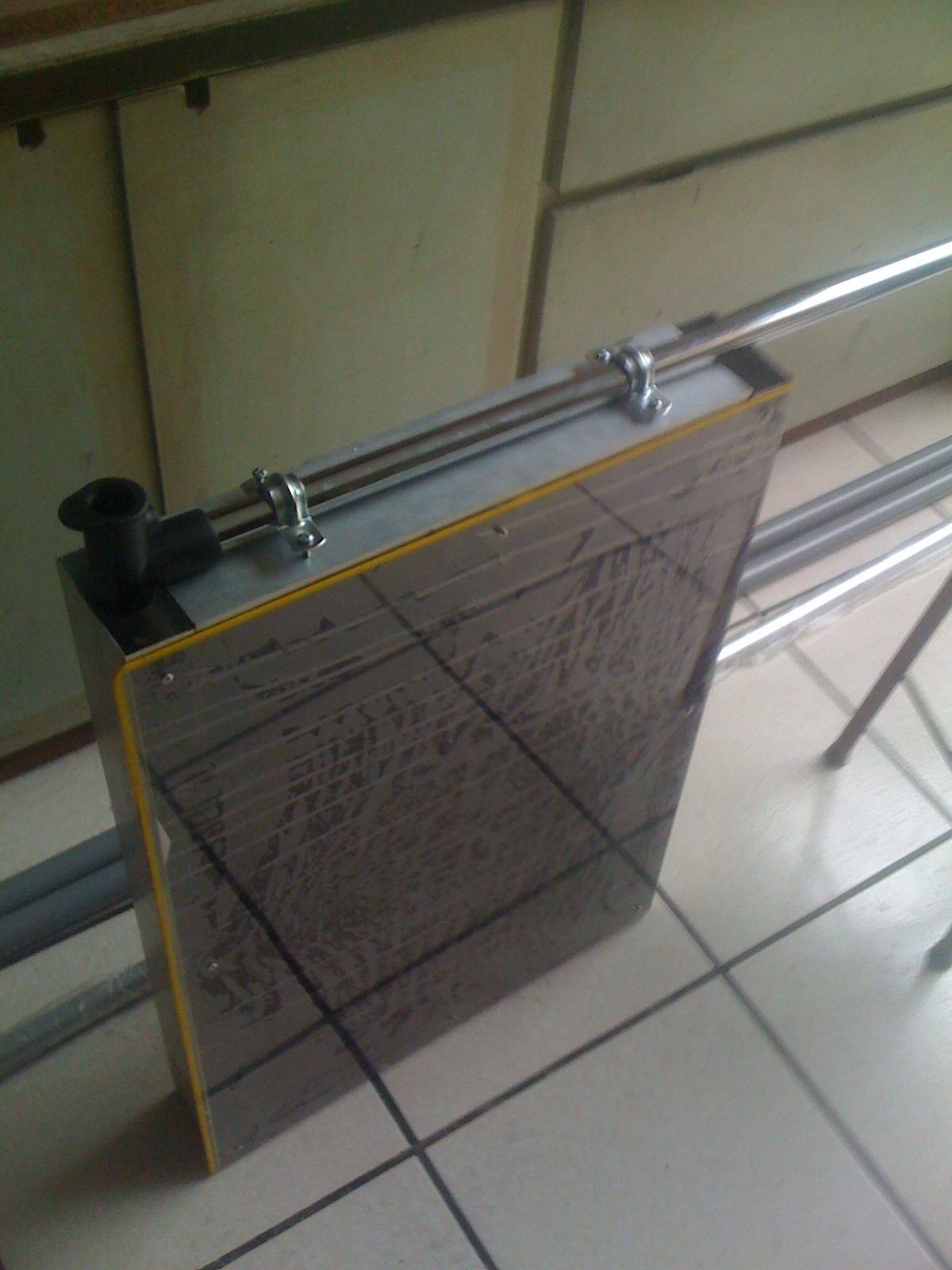
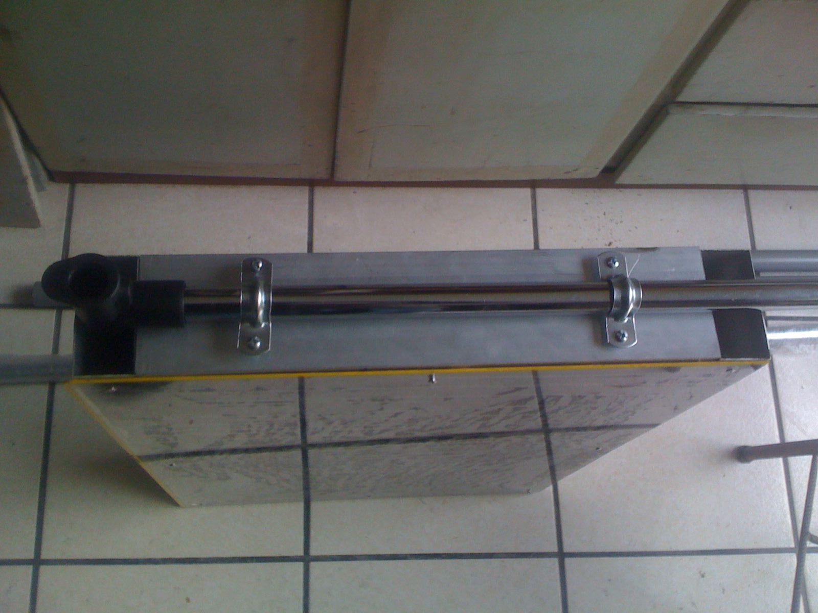
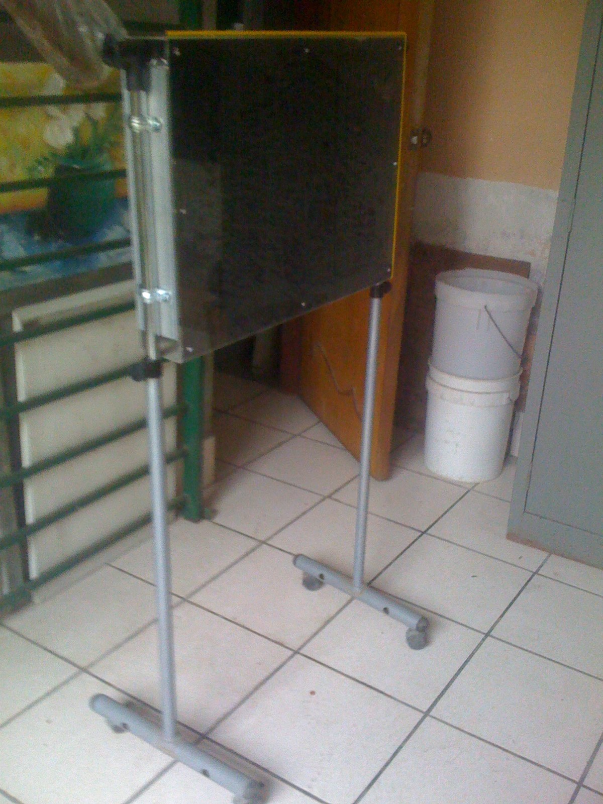
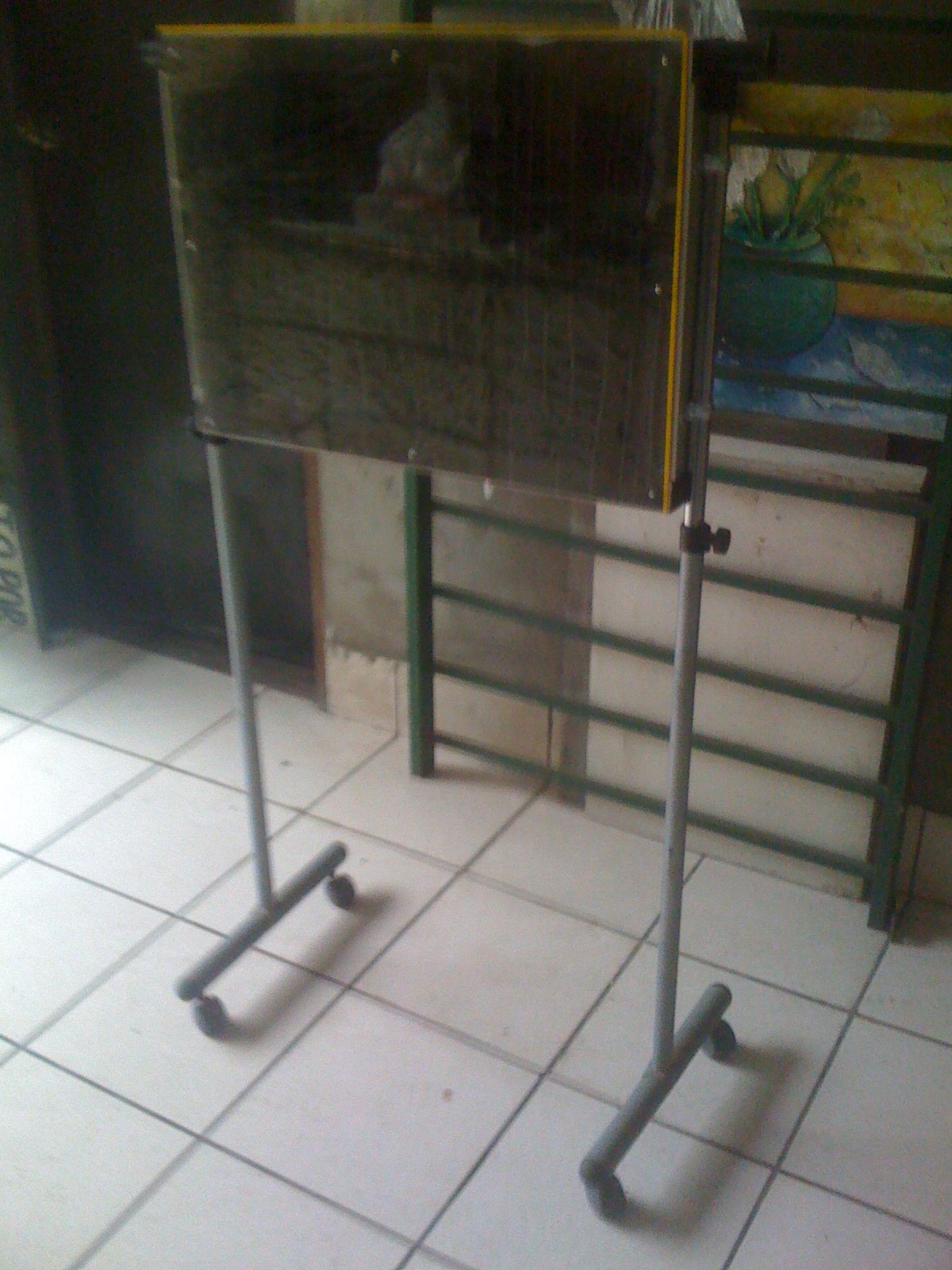
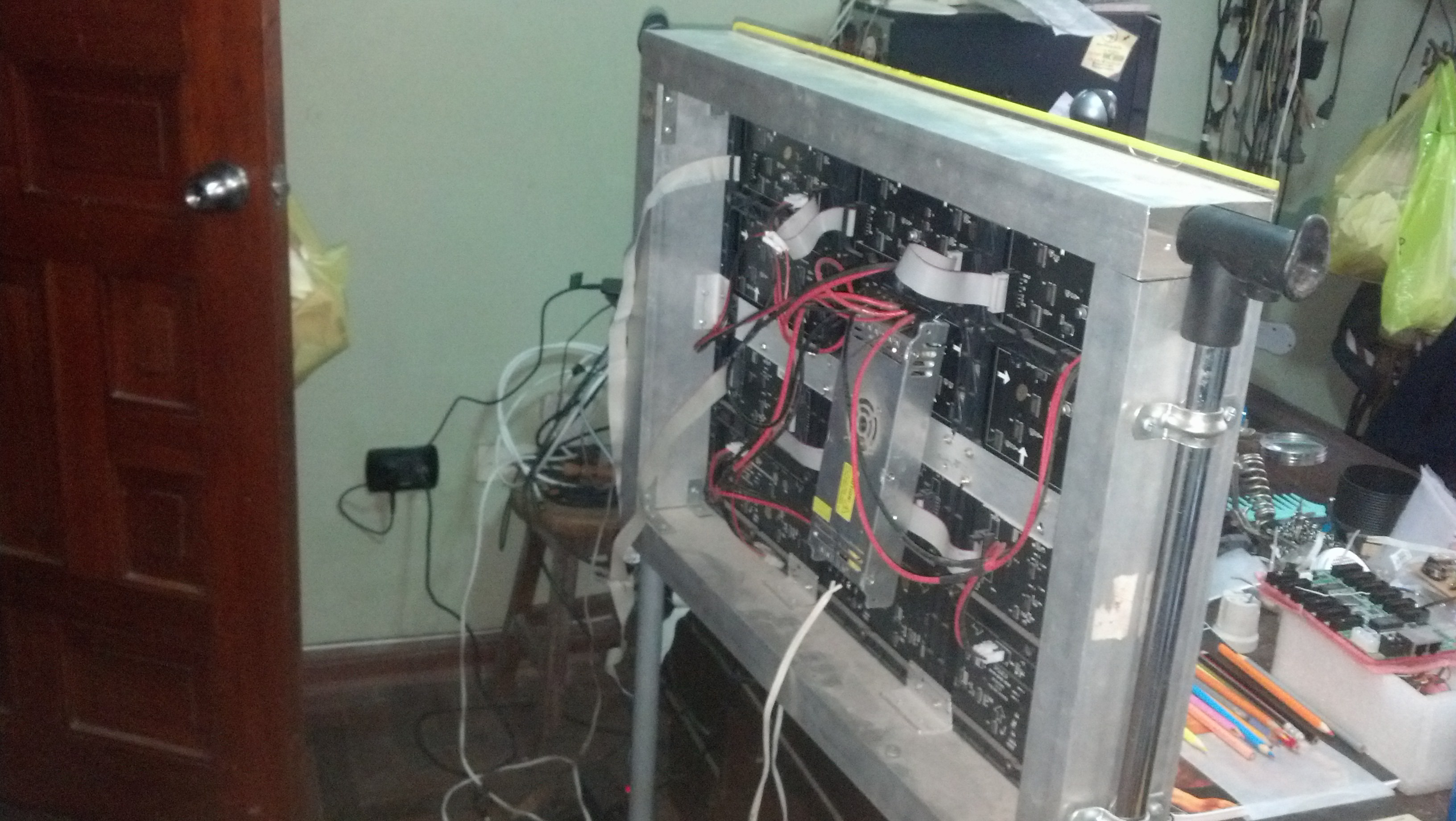
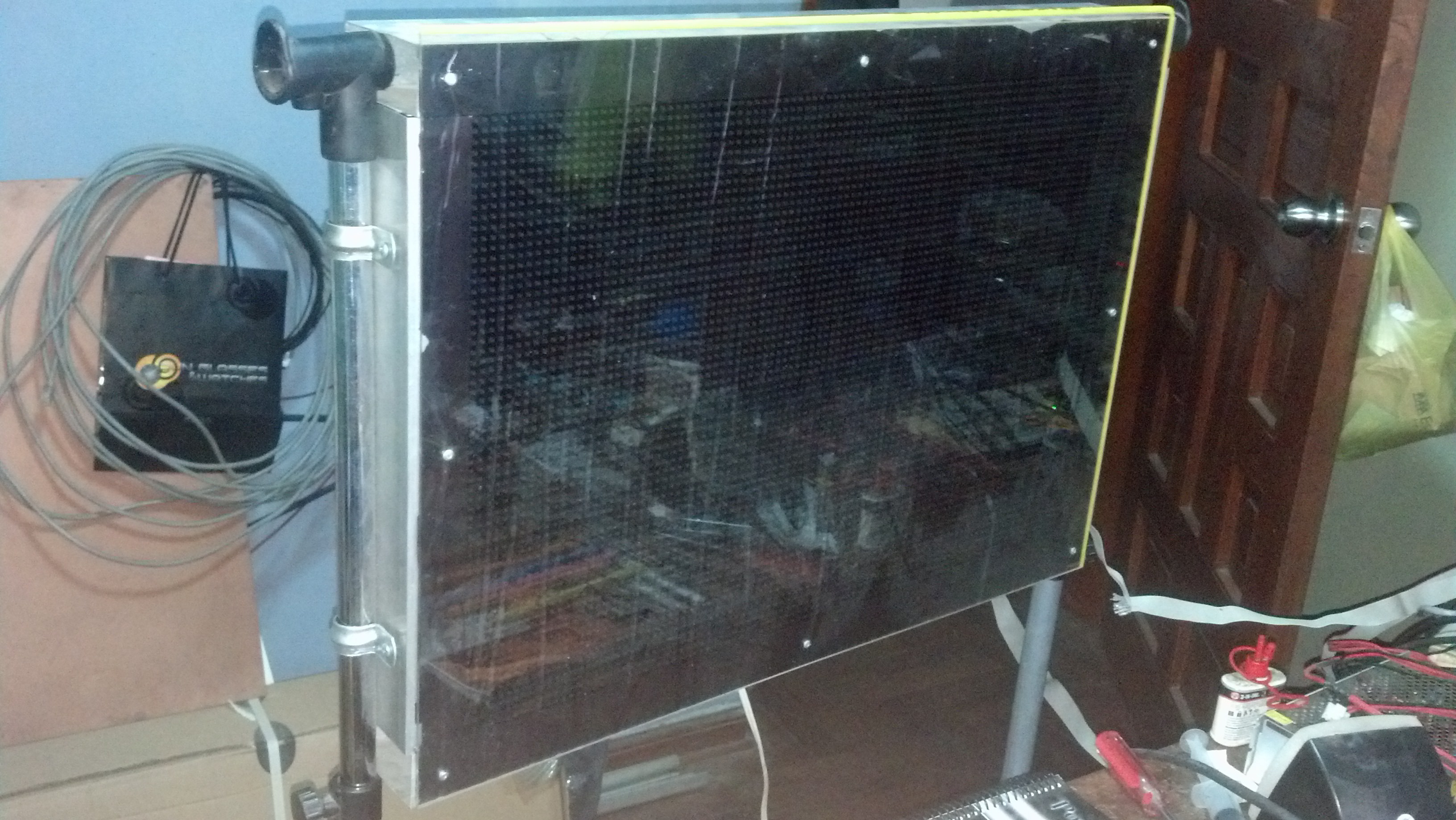
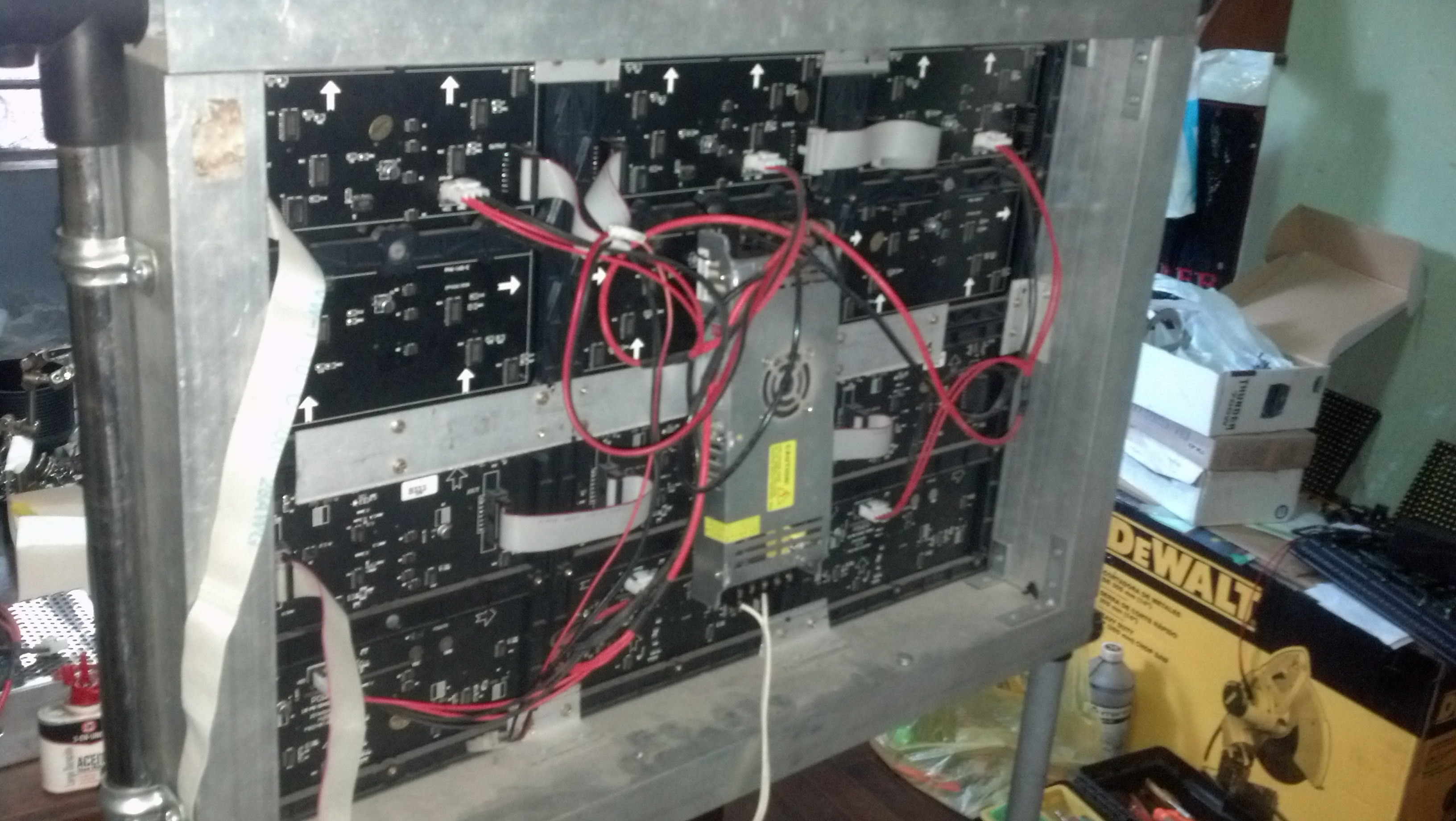
The case.
Design
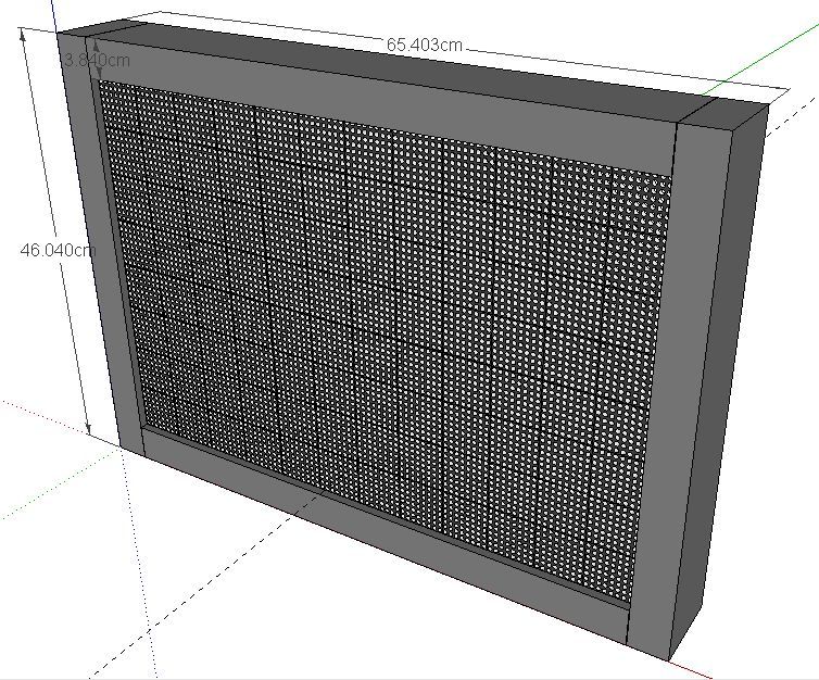
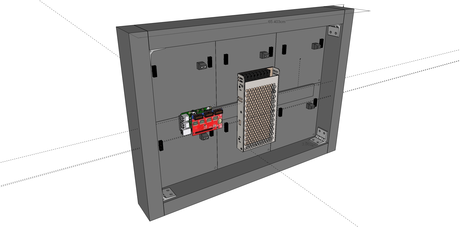
For this part, I used sketchup 3D design program. Ledboard Pi Aluminum Case 3D Design
For this, I used common rectangular 82.5 mm x 38 mm aluminum profiles, some angles and some screws. The support was founded by my Mother on the street, wasted. It has wheels as shown in pictures.