Led Strip Influenced by Weather
by vincevanschagen in Circuits > Arduino
254 Views, 3 Favorites, 0 Comments
Led Strip Influenced by Weather
In this manual I shall explain the steps you need to take to create a led strip which shows colors based on the weather. First I shall deal with connecting to the API, and then how to use the data fetched from API to manipulate the colors of the led strip. If you get stuck anywhere in the process, check the "common errors" at the bottom of the page.
Supplies
You will need:
Software
-Arduino IDE
Libraries in Arduino (Shift + CMD + L on mac or Shift + CTRL + L)
-Adafruit neopixel
-ESP8266WiFi.h>
-ESP8266HTTPClient.h
-WiFiClient.h-
-ArduinoJson
Hardware
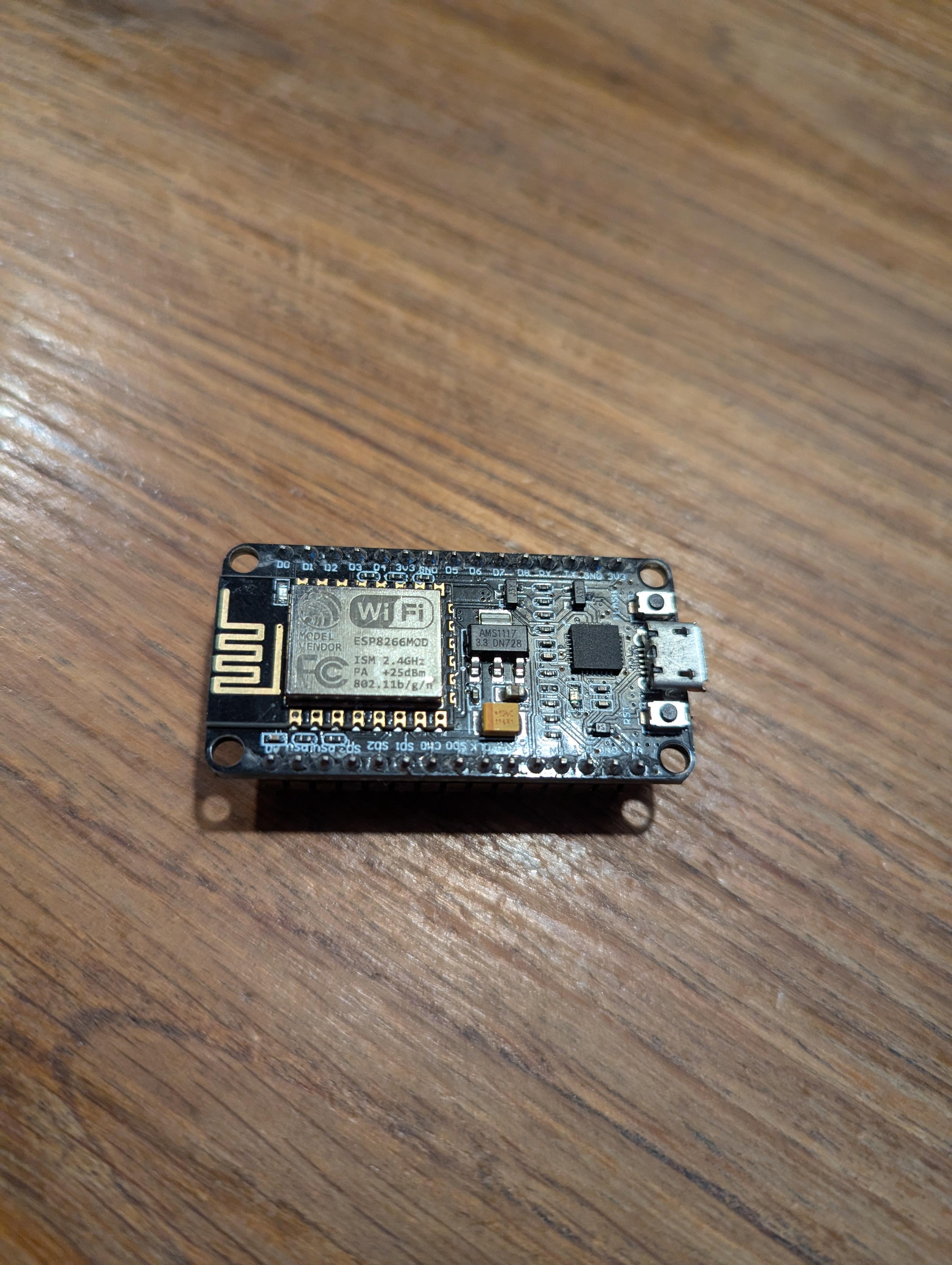
-NodeMCU ESP8266
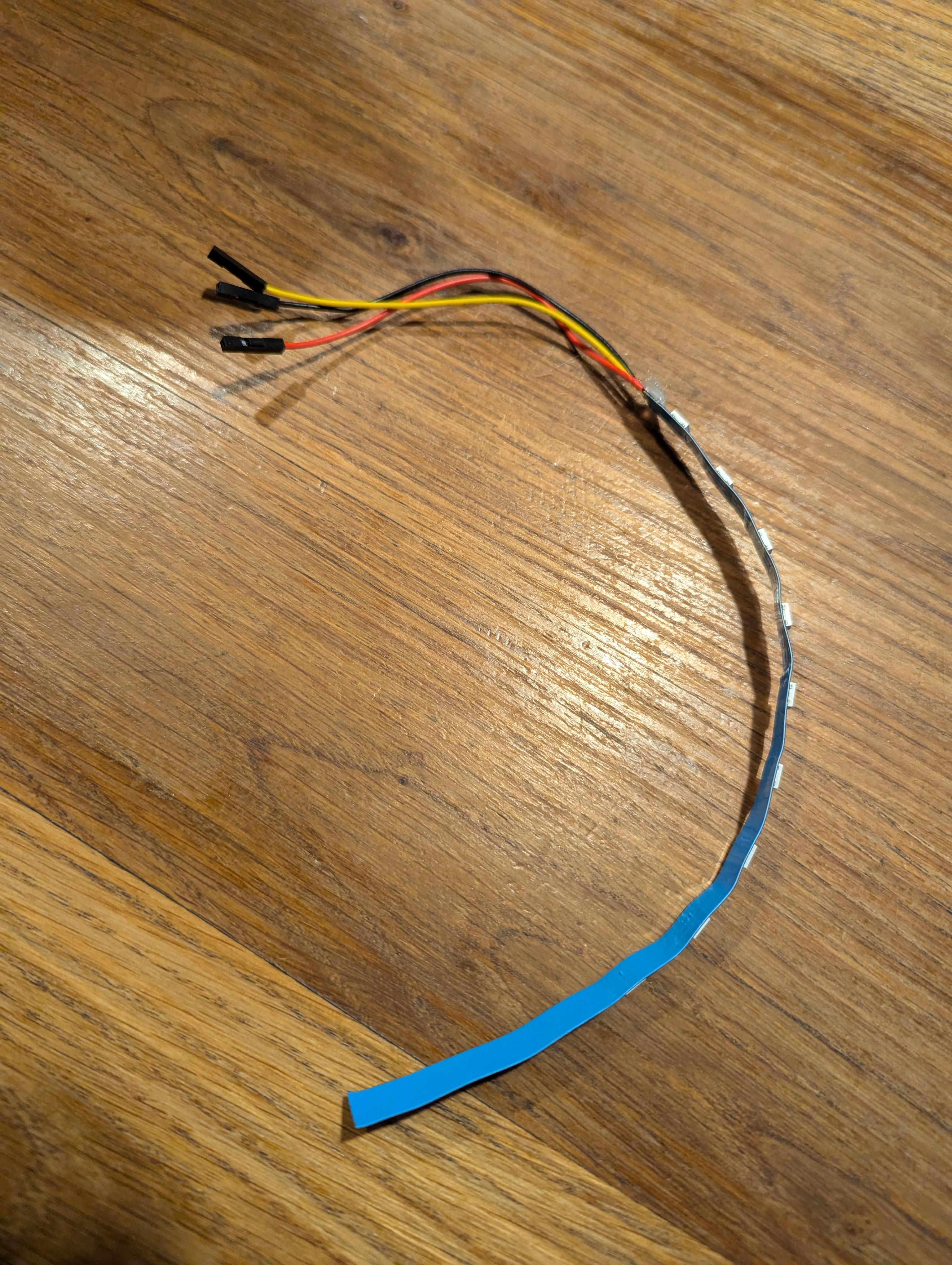
-LED strip
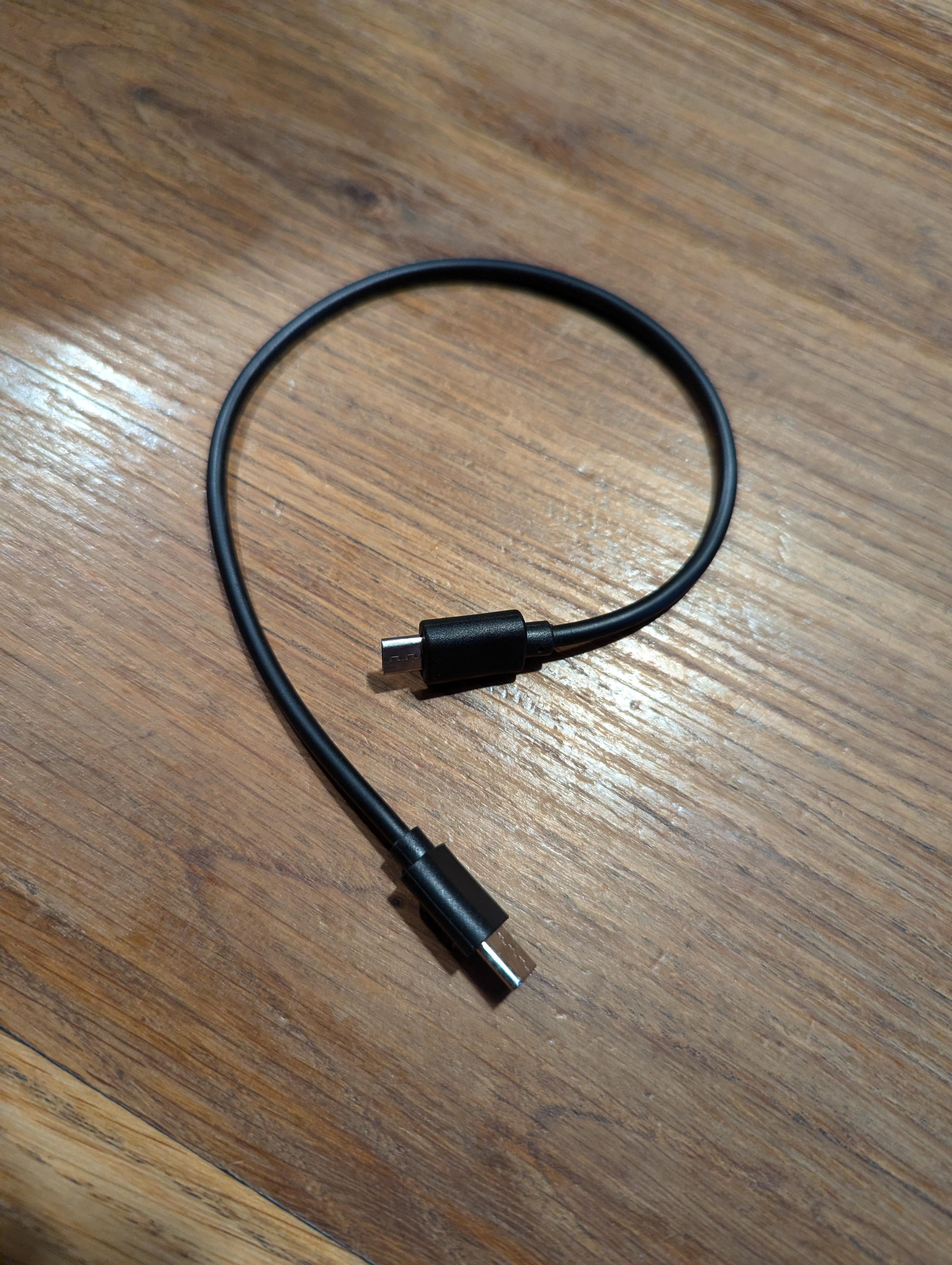
-USB cable
-Laptop (or anything you can code from)
Setting Up the Weather API

Make a free account on https://home.openweathermap.org/users/sign_up and check the email you recieved. This contains your free to use API key.
Checking If the API Works

Copy this url:https://api.openweathermap.org/data/2.5/weather?q=city,
Alpha-2code&APPID=APIkey
Replace "city", with your city, "Alpha-2 code" with your 2 numeral country code and "APIkey" with the API key you recieved in your email adress.
Paste the link with your data in a browser search bar. It should look something like this:
https://api.openweathermap.org/data/2.5/weather?q=amsterdam,nl&APPID=617ef543dd05a006ddd9c76a04496555
This should result in a JSON file showing the current weather corresponding to your entered location data.
**ERROR PREVENTION**
It can take up to 2 hours for your API to become active, so if you see the following message:
{"cod":401, "message": "Invalid API key. Please see https://openweathermap.org/faq#error401 for more info."}
make sure it has been 2 hours since you've recieved the email with your API key.
**ERROR PREVENTION**
When you copy the url, make sure you copy the 2.5 version. The 3.0 version is payed, so it wont work without a payed subscription.
Including the Necessary Libary's
To connect the weather API and the led strips you will need the following libraries:
#include <ESP8266WiFi.h>
#include <ESP8266HTTPClient.h>
#include <WiFiClient.h>
(These enable the NodeMCU to connect to wifi and make a http request)
#include <ArduinoJson.h>
(This enables the file to read Json files, which is the format the weather API presents its data in)
#include <Adafruit_NeoPixel.h>
(This is used to manipulate the led strip)
If you don't have them already, you can find them in the library.
Enter API Data in Arduino
To make a connection with the weather API, its needs acces to a wifi source, your personal API and your location data. Use the code bellow and fill in the blanks with your data.
const char* ssid = "";
const char* password = "";
const char* apiKey = "";
const char* city = "";
const char* countryCode = "";
It should look something like this:
Getting the Weather Data to Show in Serial Monitor
Now it is time to connect to the wifi and create a url to retrieve the weather data.
After that, retrieve the wifi data with the following code:
(the serial.print command is not needed but useful for keeping you updated as to what is happening.)
The next code does the following: If the connection was succesfull, it prints the Json file retrieved from the API and makes it visible in the serial monitor. It also does some error prevention and informs you if this fails.
Upload your code by entering CMD+U (mac) or CTRL+U
Wait until the upload has completed (you will se the text "done uploading" if successful)
and open the serial monitor by entering Shift+CMD+M (mac) or CTRL+U
If done correctly, you should now have the weather data printed in your serial monitor.
**ERROR PREVENTION**
If you don't see anything in the serial monitor, edit this line of code:
to this:
(Don't do this for to long, because you have a 1000 free requests per API. So with this delay you have send a 1000 request within 1000 seconds.)
Setting Up the Led Strip Connection
Now that we have data we can base the color of the leds on, its time to set up the lights.
Put the following code before the void setup.
First you define the pin you are going to connect the strip to. I chose D4
After that you define the amount of leds that your led strips has. In my case this is 12.
Then you define what strip means. We will use this throughout the code.
put this in the void setup code:
the first line initializes the NeoPixel strip and prepares it for use. The second line sends the current pixel color data to the strip, making any changes visible.
Copy the following code and paste it at the bottom of your code.
The setLEDColor(uint32_t color) function is a reusable way to set the color of all LEDs in the strip at once.
It loops through each LED and sets its color to the value provided as a parameter, then calls strip.show() to update the strip and make the changes visible.
**ERROR PREVENTION**
Make sure you connect the right pins on te right place. Where the strip connects 1 should say "gnd". This is the grounding of the electricity circuit. The middle one should connect to "3v3". This stands for the amount of volts and is also used to make the circuit work. For the final connection you can choose D1 all the way up to D8. But make sure to define it according to that number in the first line of code in this step.
Test Your Code
(I highly recommend to test your code in between. If your code happens to fail; check the "error prevention" sections.)
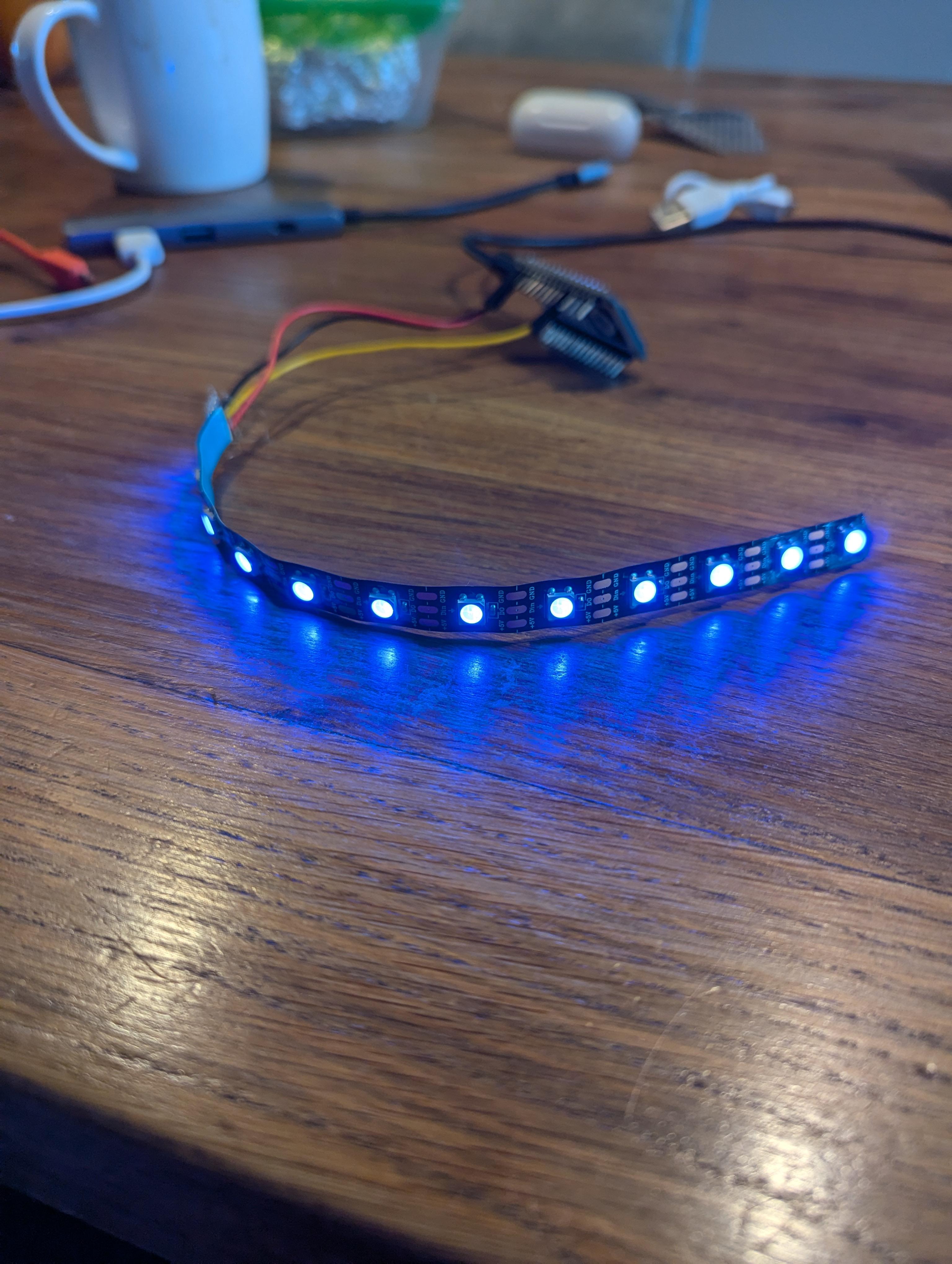
To test if it works, check the current weather in your city. subtract 1 degree of that number and paste it in the "yournumber" part of the following code
copy the code above, and paste it in the void loop beneath the following line:
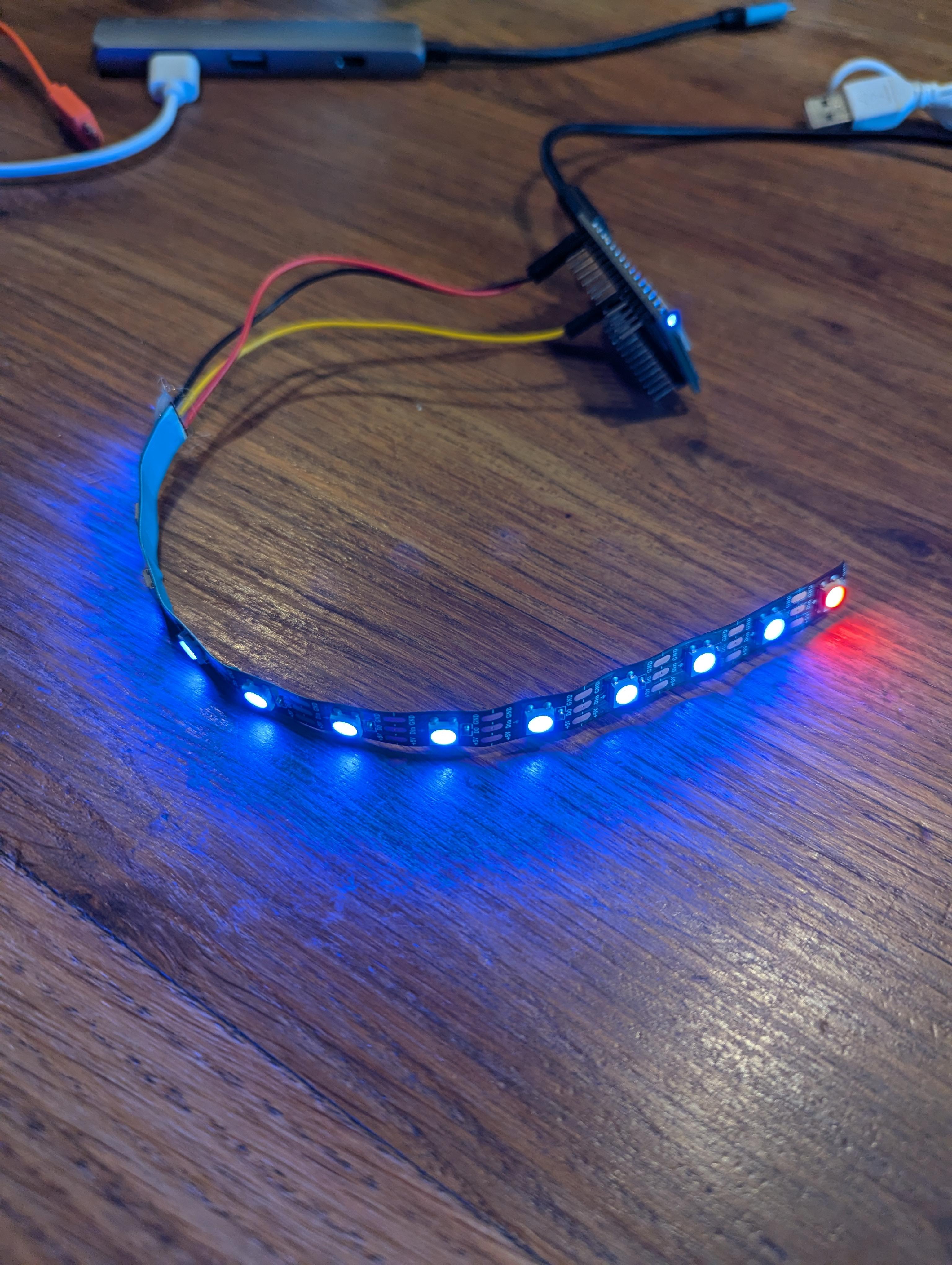
if it is higher than your entered number, which it should be, the led strip will turn blue. (see pic)
**Error prevention**
If your led strip is not turning blue, check if the output in your serial monitor is correct. Convert the "temp" value from kelvin to celsius.
Finetune the Colors

Now that we know that the colors are working, its time to make code to match our goal: Using the colors to get recommendations for cold therapy.
To do this, we need to specify our wanted outcomes.
-If the weather is above 18 degrees, I want the strip to be fully blue.
-if the weather is below 18 degrees, I want the first 11 to be blue and the rest to be red.
-if the weather is below 14 degrees, I want the first 8 to be blue and the rest to be red.
-if the weather is below 10 degrees, I want them all to be red.
The code needed to get this result is the following:
You also need to create a function that defines "setPartialColor" to control the color of individual LEDs in the LED strip, to set a specific number of LEDs to one color (blue) while setting the remaining LEDs to another color (red).
With this added code, depending on the weather, it should light up either fully blue, partially blue, or fully red.
(to check if your code works, check the weather at your city and see if the led lights up according to the value.)
Common Errors
Uploading code fails or the wrong device settings are used.
Solution: Make sure you have selected the correct board under Tools > Board. Select "NodeMCU 1.0 (ESP-12E Module)".
Wrong kind of USB.
Solution: Make sure the USB you are using allows for data transferring. Some usb cable's are only for charging.
Wierd output in the Serial Monitor
Solution: Ensure that the baud rate in the Serial Monitor matches the one in your code.
Underneath the "void setup" you should see the following line of code:
Make sure your baud rate matches this number.
Unexpected behavior or inability to upload code.
Solution: Check the wiring of external components connected to the NodeMCU (e.g., sensors or LEDs). Miswiring can cause power draw issues, incorrect readings, or even prevent uploading the code.