Lasercutting a Twisting Cardboard Lamp : Rhino + Grasshopper
by mrannermore in Circuits > Software
3806 Views, 25 Favorites, 0 Comments
Lasercutting a Twisting Cardboard Lamp : Rhino + Grasshopper
Hello fellow makers !!!,
Let's make some awesome lamps today ! The objective of this tutorial is to show you how to use parametric tools to create intricate and beautiful forms with ease and comfort. This tutorial is intended to rouse the interest of those who are new to parametric design and also those who are well versed in the field. The use of parametric design alongside digital technologies is becoming a large field of study that many people are delving into, hopefully this gives you a boost. I will not be teaching you how to use grasshopper but I will be breakdown what each parameter does. I will make a series of grasshopper tutorials in the future but for now I want you to have fun and get your feet wet.
Here are some great resources to learn grasshopper - Daniel Christev
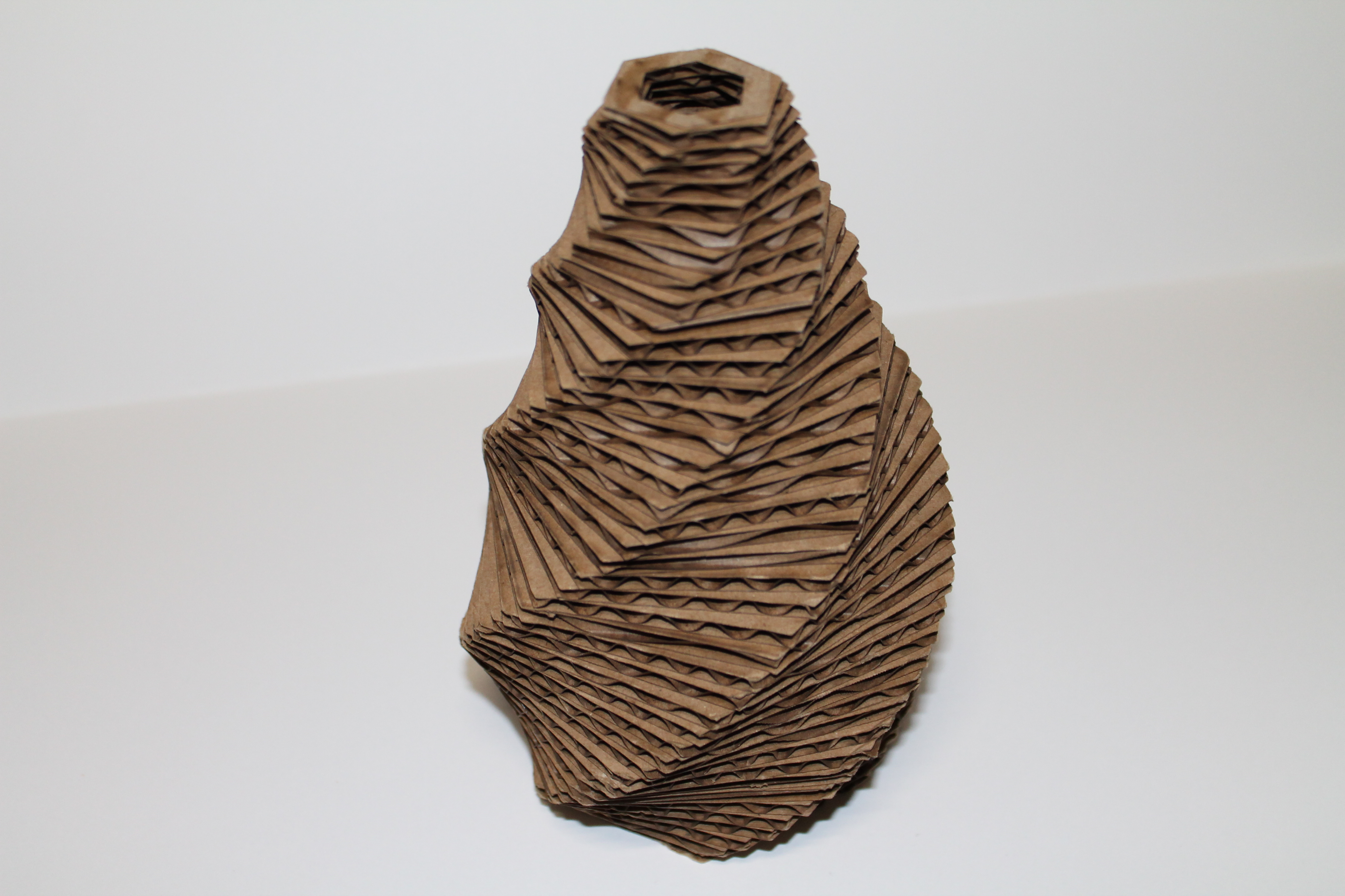
The main material for this project is cardboard, if you don't have any cardboard no worries you can use any material you please. The reason I choose cardboard is because it is an underutilized material. It is recyclable , inexpensive and easy to cut. You also get an added layer of texture if you know how to use it.
Let's begin !!!
Downloads
Step 1 : Getting Started...
Open Rhino
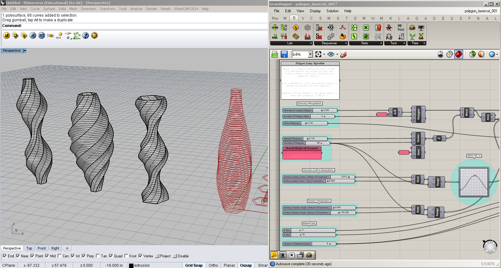
Once you've downloaded the grasshopper definition, open up a new Rhino file with inches as your base unit. The numbers in the grasshopper file will correspond to whichever units are selected in rhino space, and for me inches is the easiest to visualize, you can always alter it to suite your needs ( the beauty of parametric design ) !
Opening the Grasshopper File
If you have Rhino but not grasshopper, go download it! It's totally free, get it here Grasshopper !! When you open the grasshopper definition you will immediately see the full geometry pop up in Rhino space. Don't get scared, we will be able to alter the shape, size , rotation and form of the geometry using simple procedures. I also added comments within the file to help you know what each color group refers to.
Modifiers
The cool thing about the whole definition is that you don't have to create any Rhino geometry. I made it with the intent of having everything contained in the definition, all you have to do is alter the Number Sliders and watch the lamp change before your very eyes !!! This gives the beginner who doesn't have a firm grip in parametric design a starting point in creating complex forms and also gives the curious seeker a look of how data correlates with each other.
Step 2 : Geometry Manipulation
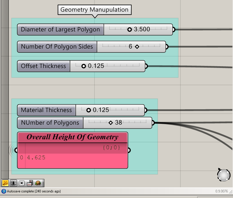
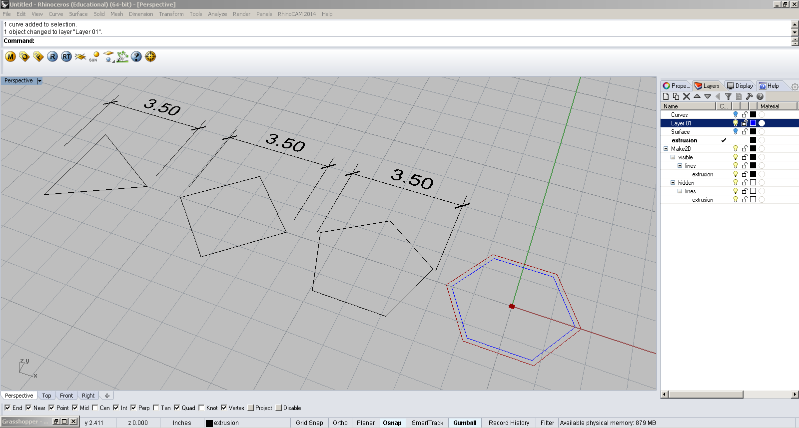
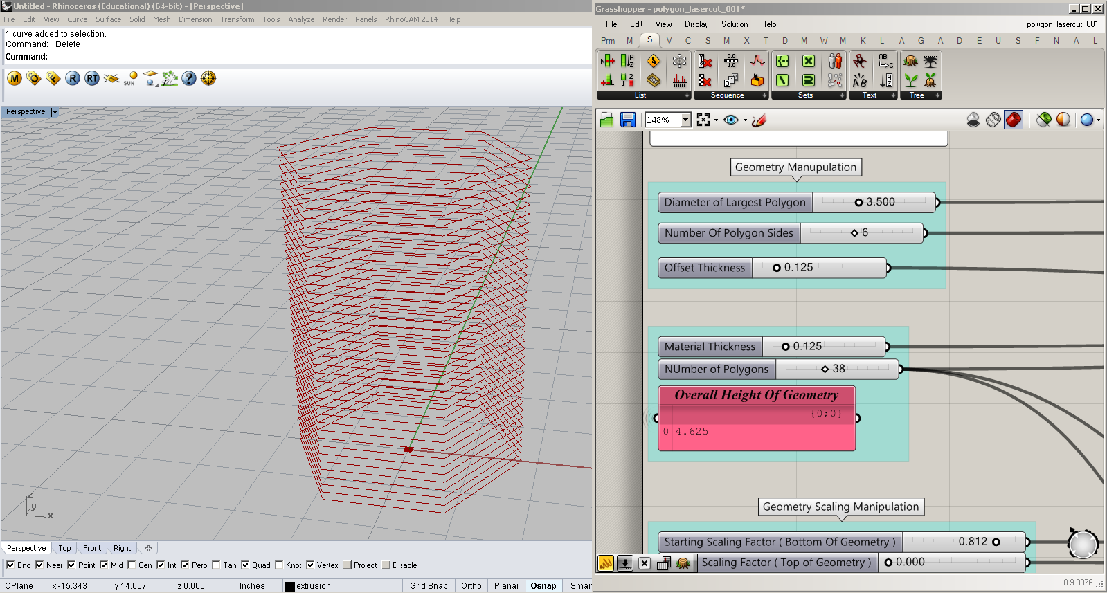
This definition has various parameters aka different types of controls that you can play around with to manipulate the form of your object. Let's start with messing around with the geometry...
Diameter of Largest Polygon
The diameter of the largest polygon refers to the length of a circle that the polygon is within. Now this circle doesn't exist on the screen but it is the underlying basis of how all polygons are created in computer programming. So changing this number changes the size of your shape.
Number of Polygon sides
We all took geometry before ( I hope ) but if you don't remember each polygon has a X number of sides. This allows you to change you polygon so you're not stuck with just one shape.
Offset thickness
This refers to the distance that we are offsetting the original polygon size. In this case it says 0.125 which equals 1/4 inches (if you're using inches, again you can change the units to change your needs ) . We want to make the overall object hollow to add lights or a supporting structure to hang it with so we need to offset the geometry for the laser cutter can know to make the appropriate cutouts.
Material thickness
This is the thickness of your material size. When changed the incremental distance between each successive layer will alter according to the thickness you set it to. This number can go from paper thin to brick thick and beyond , as long as you have a material with the corresponding thickness you're good !
Number of Polygons
The number of polygons refers to the number of layers you are creating. If it's 3 then you will have 3 layers, if it's 100 you will have 100 layers stacked on top of another. Take note that the more you increase the number of polygons the higher your overall height will be. There is a correlation between the material thickness and the number of polygons, changing either one changes the overall height of your project.
Step 3 : Scaling and Rotation Modifiers + Form Manipulation
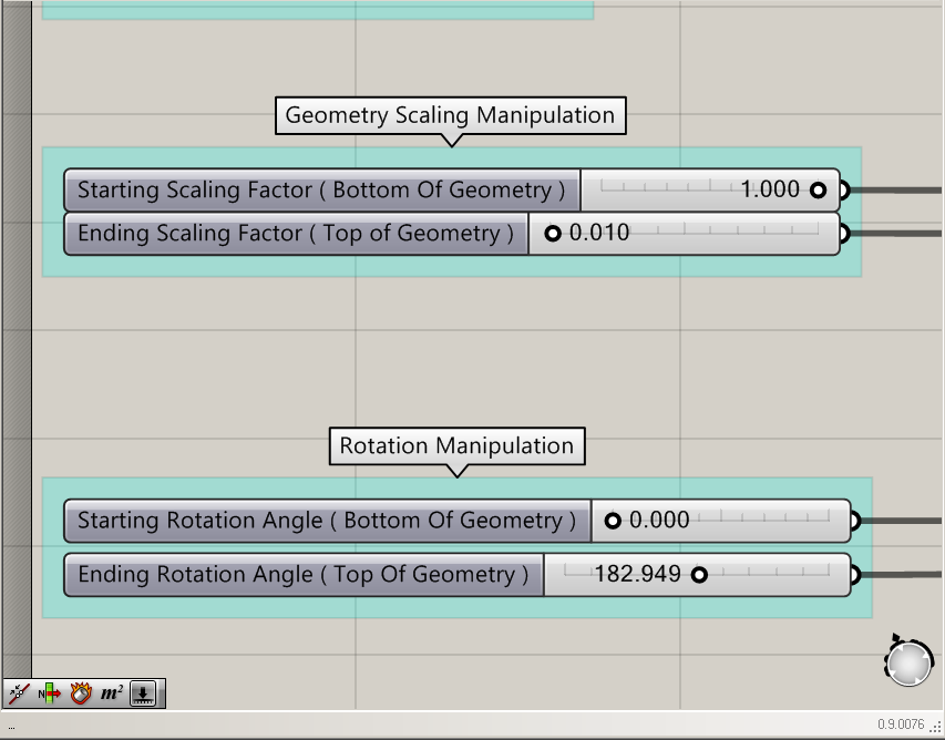
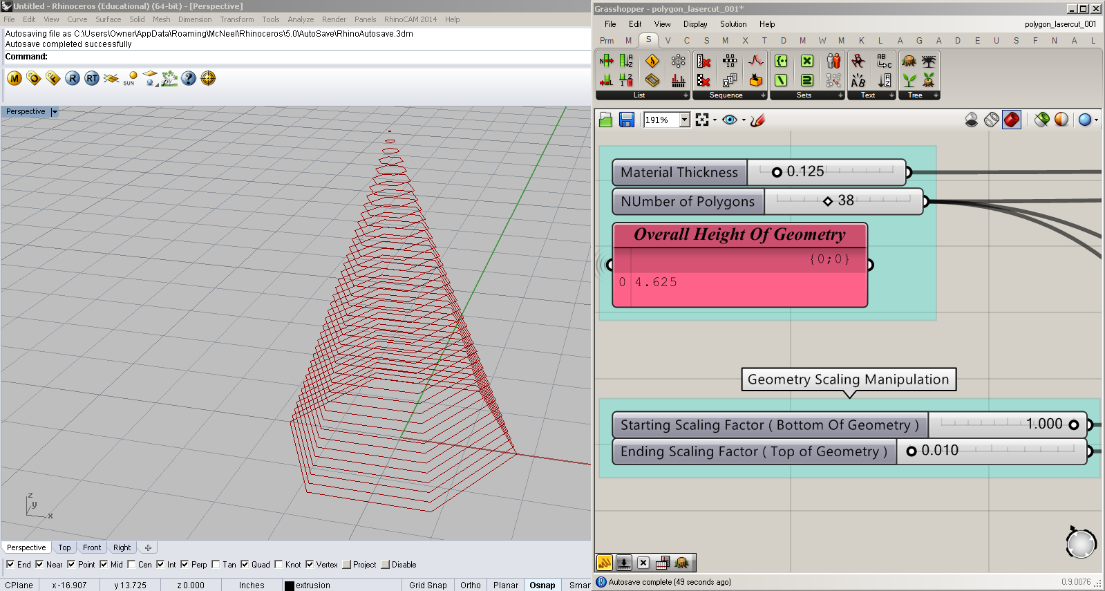
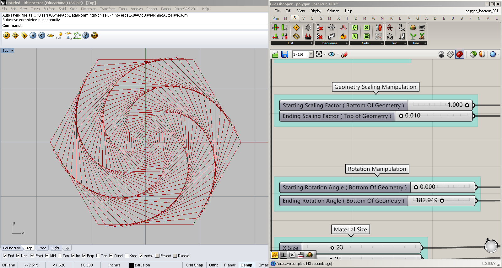
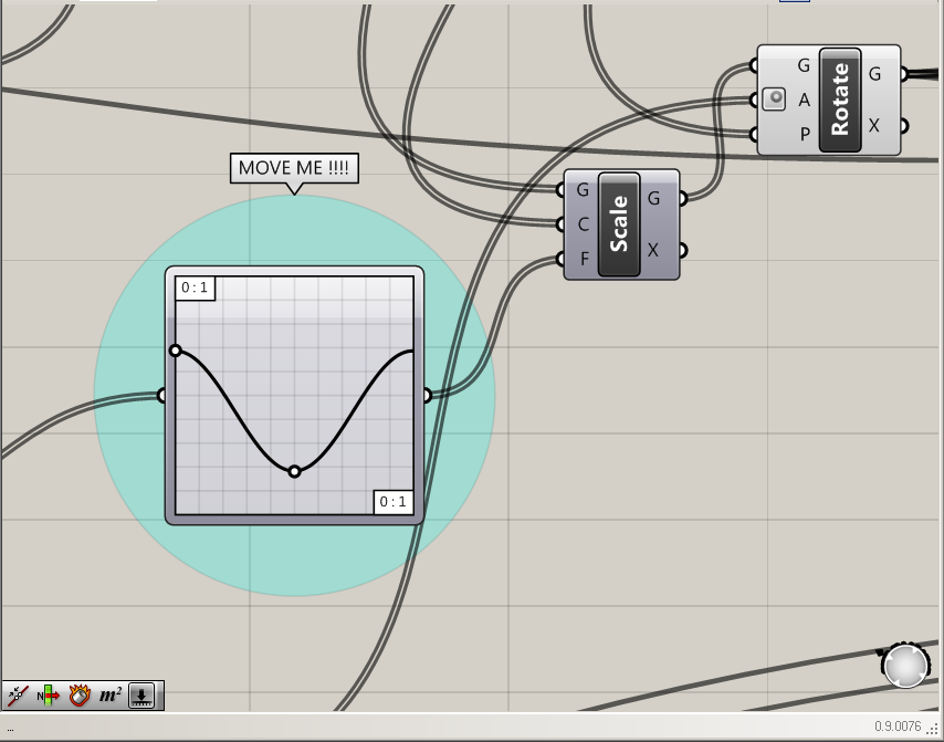
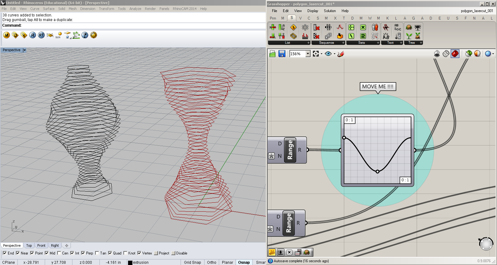
Here we break down the scaling , rotation and form changing of the object within the definition.
Start and End of Scaling Factor ( Bottom and Top of Geometry )
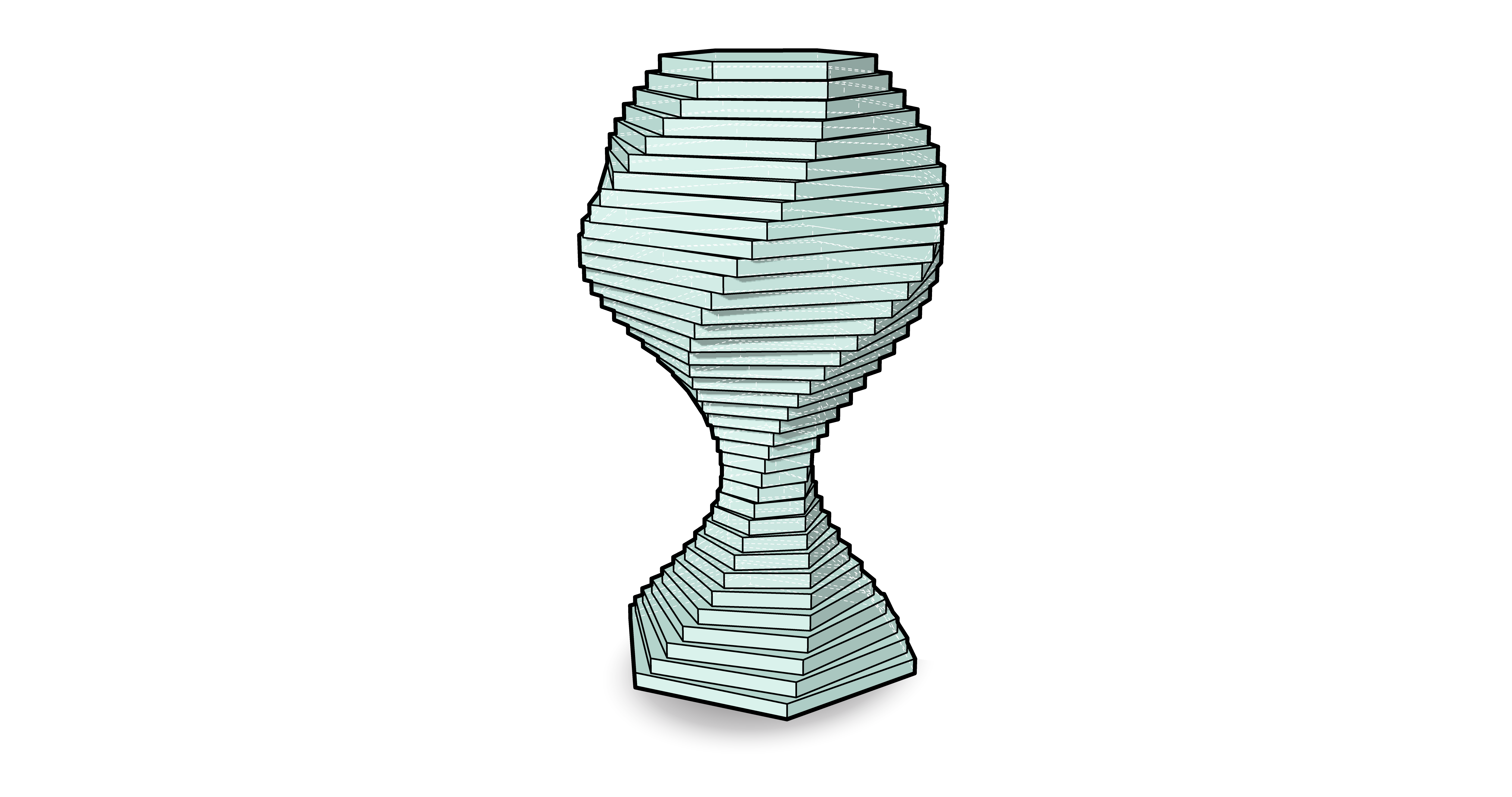
Scaling may seem like a difficult concept to grasp but I assure you it's quite simple. In the example the start and ends are set differently, here's whats happening. When the number is set to 1.00 we are telling grasshopper that we want to scale the object by a factor of 1 which would leave the object in its original state because anything multiplied by 1 equals itself. Hence the bottom of the object being the original size you set the Polygon Diameter .If we want to make the object large we increase it larger than 1 and if we want to make it smaller we decrease the number below 1. In the photo you can see how the size of the geometry shrinks as it goes up, the bottom being 1 x the original diameter and the top being 0.1 x the original diameter .
Start of Rotation Angle + End Of Rotation Angle
Now the rotation works in the same that the scaling does but instead of shrinking or growing the geometry we are just rotating each polygon by a certain degrees. In this case the bottom of the geometry is being rotated by 0.0 which means no rotation and the top by 182.949. In between is a range of numbers that is created from the number of polygons we have, making a number for each polygon we have ( think of a step , incrementally going higher).
Graph Mapper ( Form Changing )
This component adds a lot of complexity to any project and is a powerful tool. What the graph mapper does in essence is alter the data that is coming in based on different graph types. By changing the graph you change how the numbers are configure and hence change the geometry in this case. The data that we are manipulating is the scale and rotation of the geometry, when we alter this piece of date we can start to morph the overall form based on the type of graph we choose giving us a wide range of movement. For further explanation on the graph mapper go here - Graph Mapper .
Step 4 : Set Your Material Size
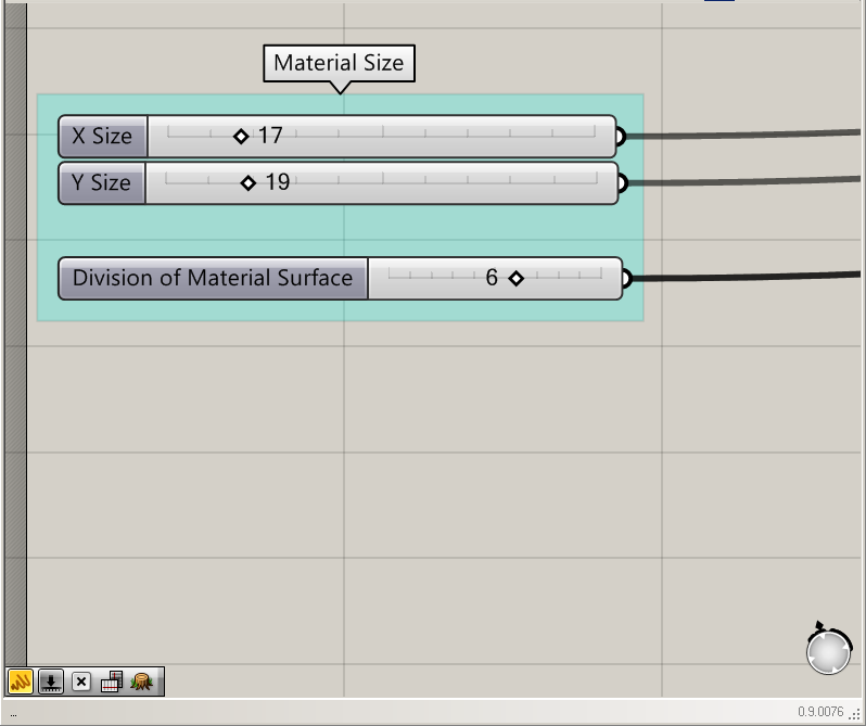
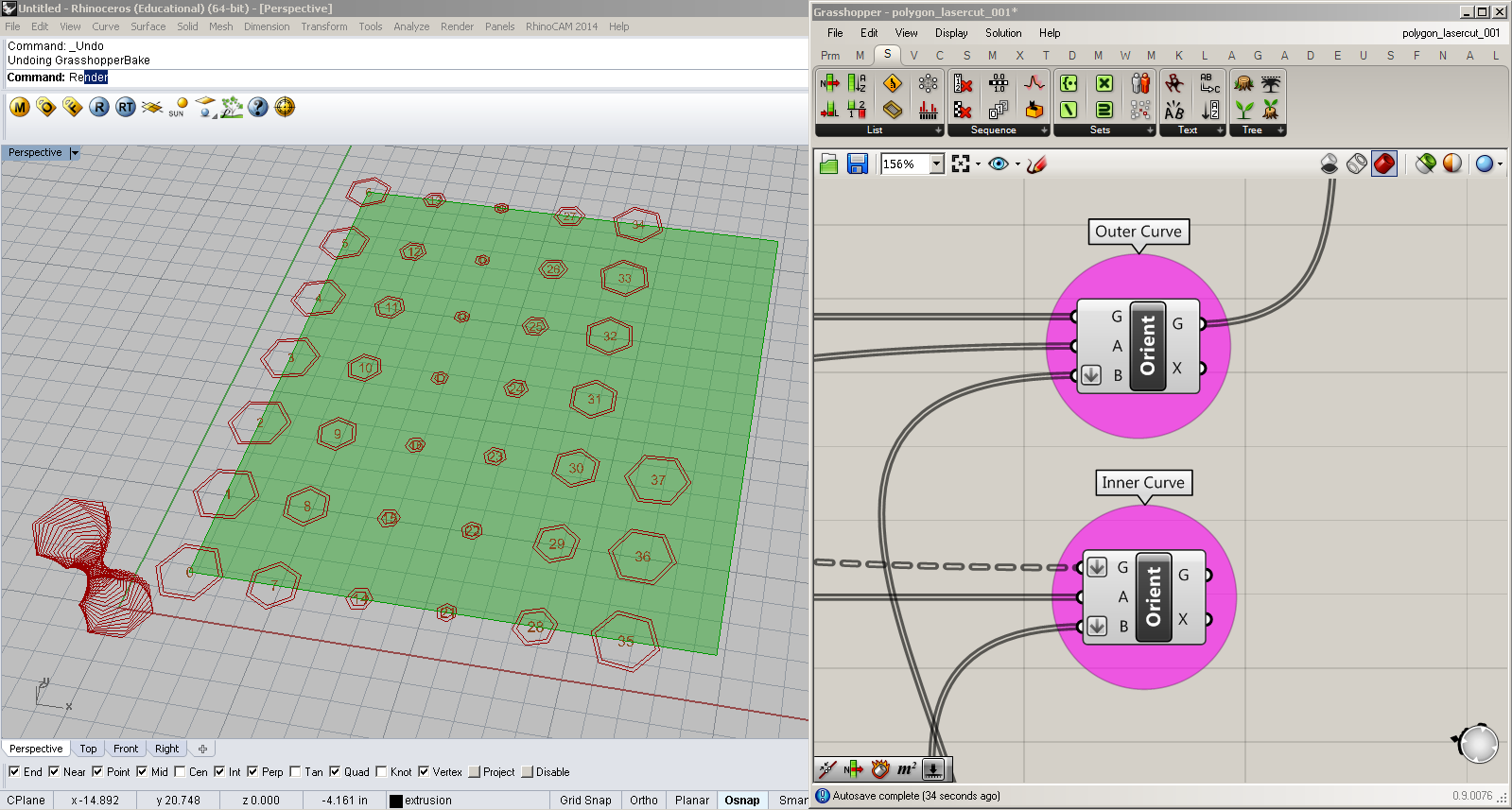
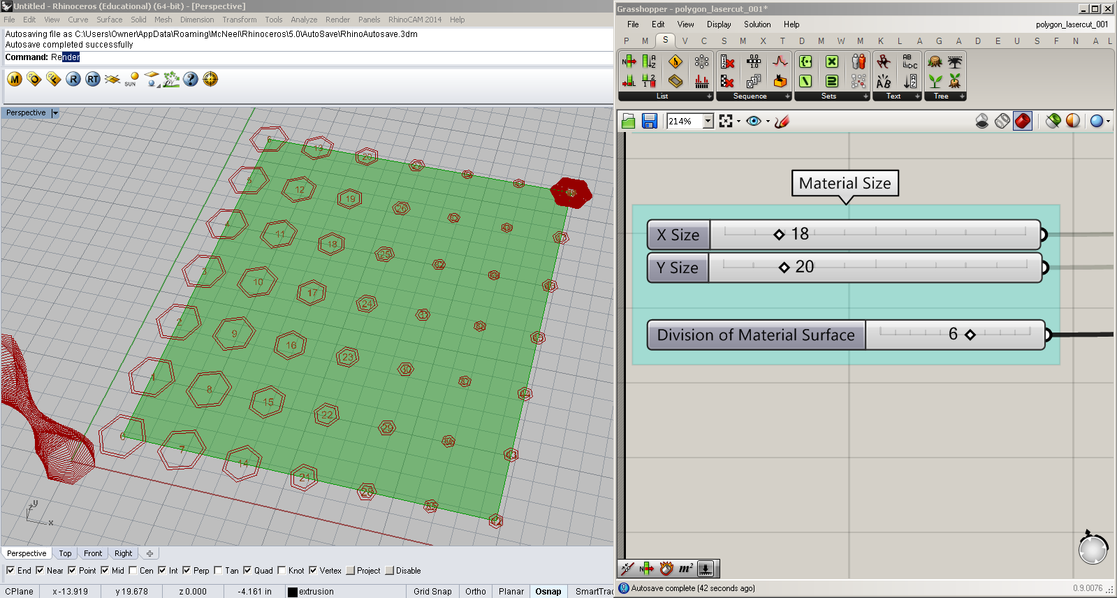
This part of definition is meant for placement of your geometry on a sheet of paper. It orients the geometry down a sheet size that we define with X and Y values. So in this example the X value is 17 and the Y value is 19 making my overall sheet size 17 inches x 19 inches.
Division of Material Surface
This number signifies that amount of divisions the surface is being broken up into or you can think of it as square slices . What this means is that the surface is being divided 6 x 6 = 36 divisions, these are going to provide us with the space to place our geometry flat on the sheet. At one point you will get an error like the last picture and wonder what the heck is going on. What is happening is that if we have 36 divisions and 48 objects the last 12 objects will get piled on top of each other in the last slot because we have no room to put them, no worries easy fix. Just bump up the number of divisions and you're golden.
Step 5 : LaserCut It , Stack It , and Voila !!!
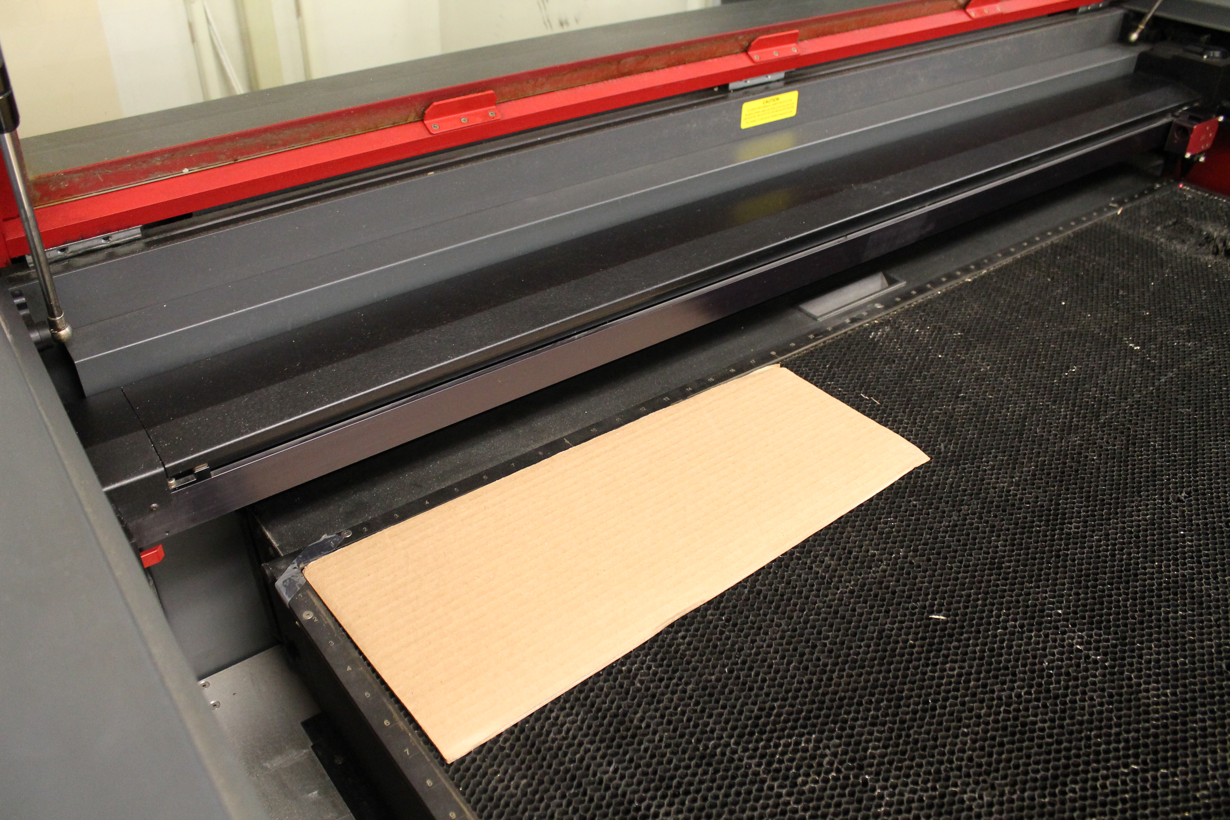
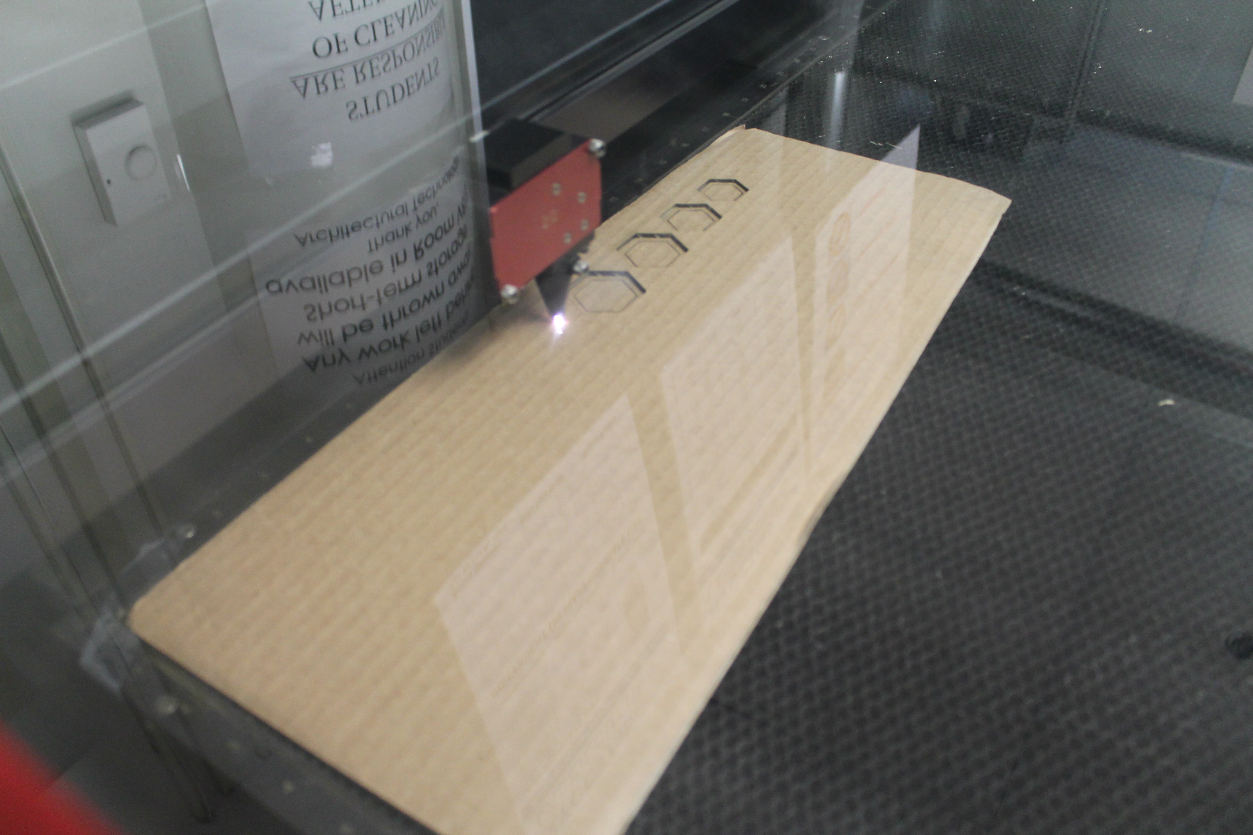
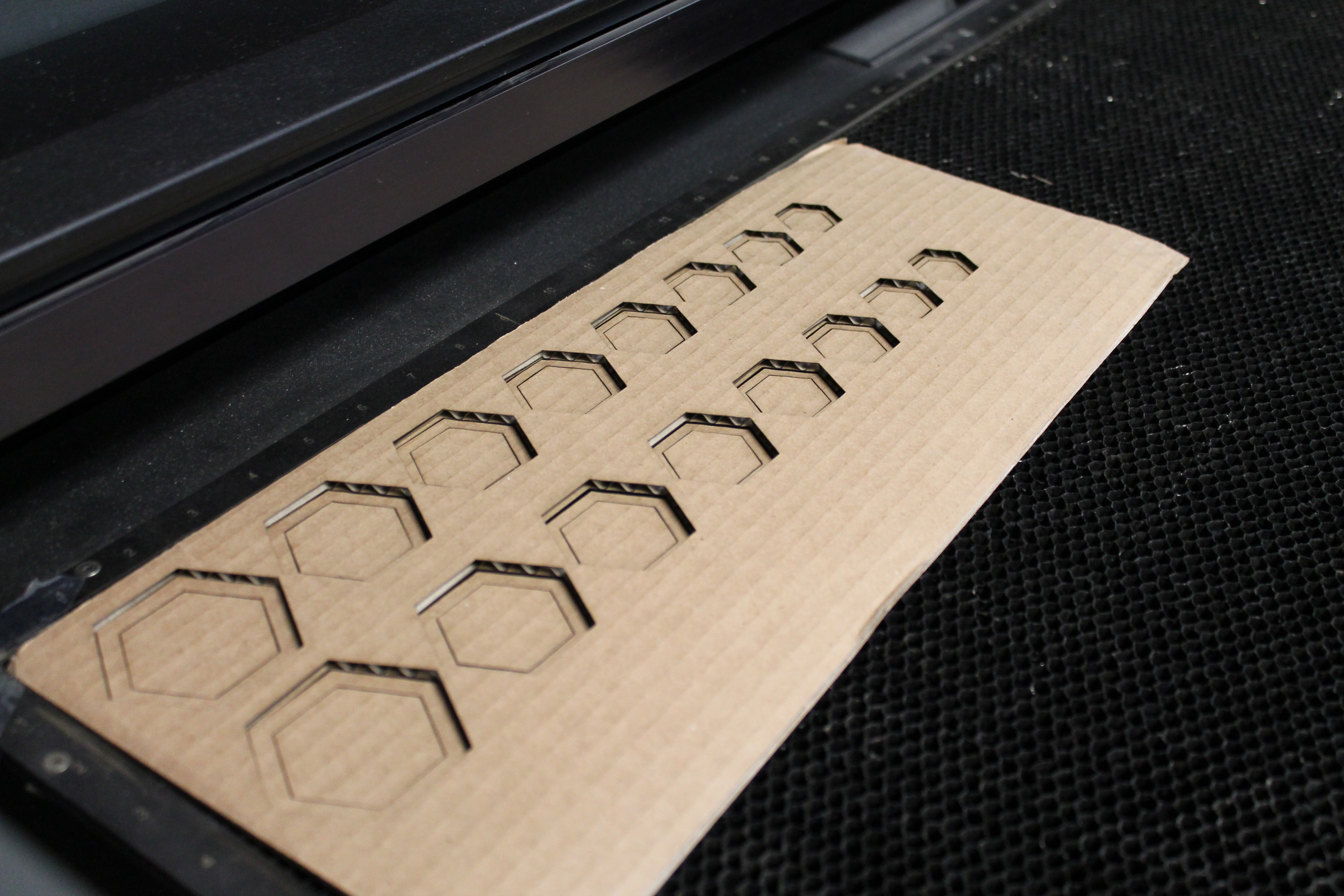
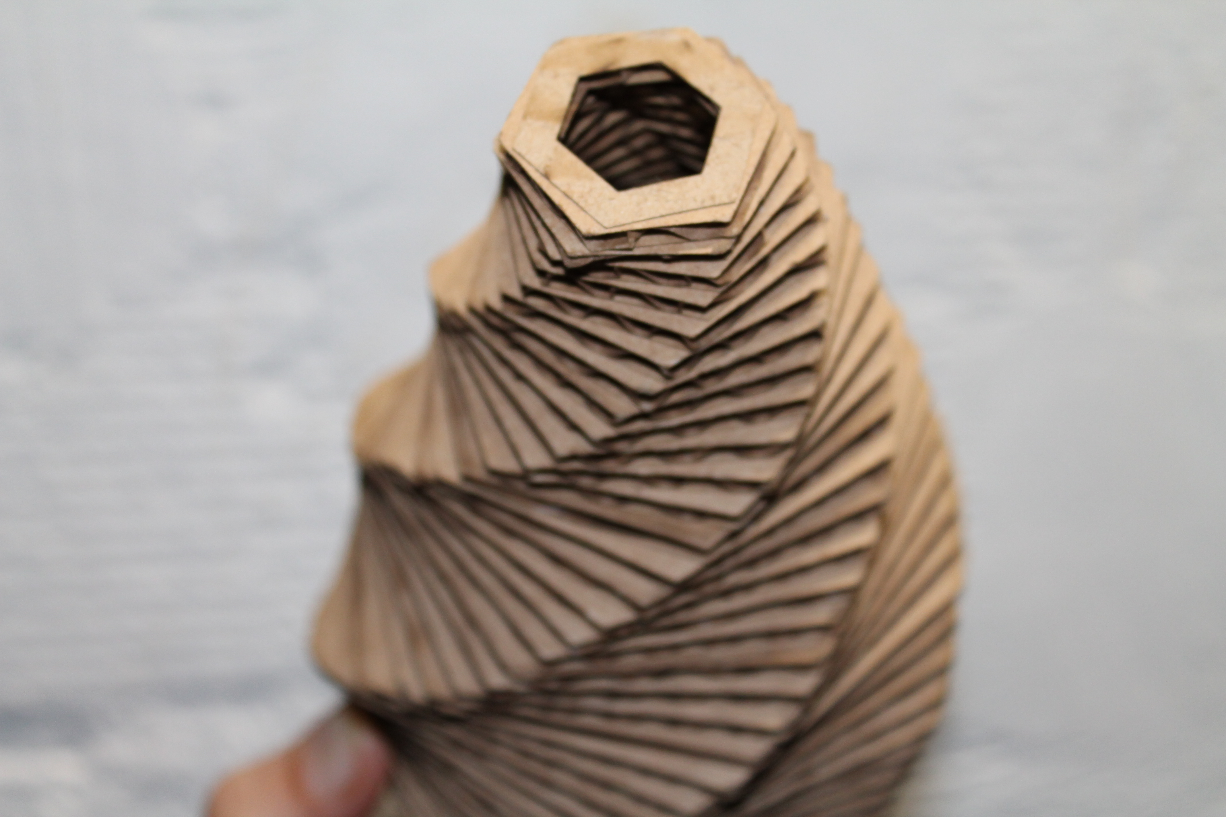
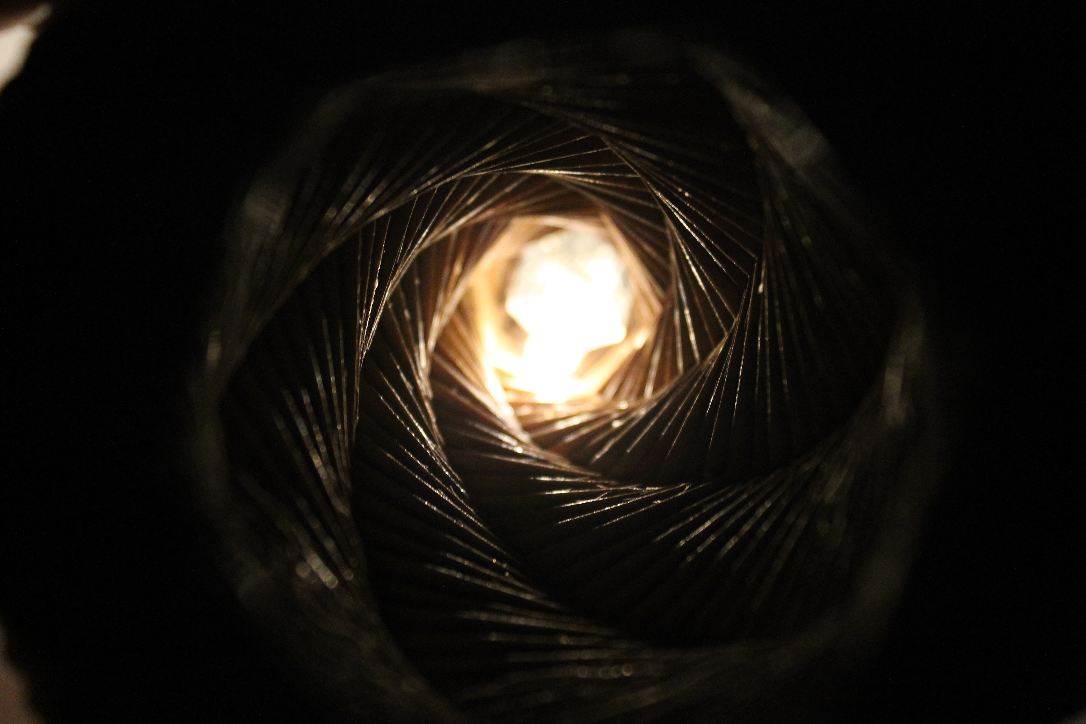
Put your material in the lasercutter and let it rip.
The beauty about the definition is that it allows you to see how the rotation will look. You can always alter how you lay them out to cut and stack them as you please but when you cut the polygons at a certain angle on cardboard you get different cuts pattern based on the rotation placement. Cool huh !
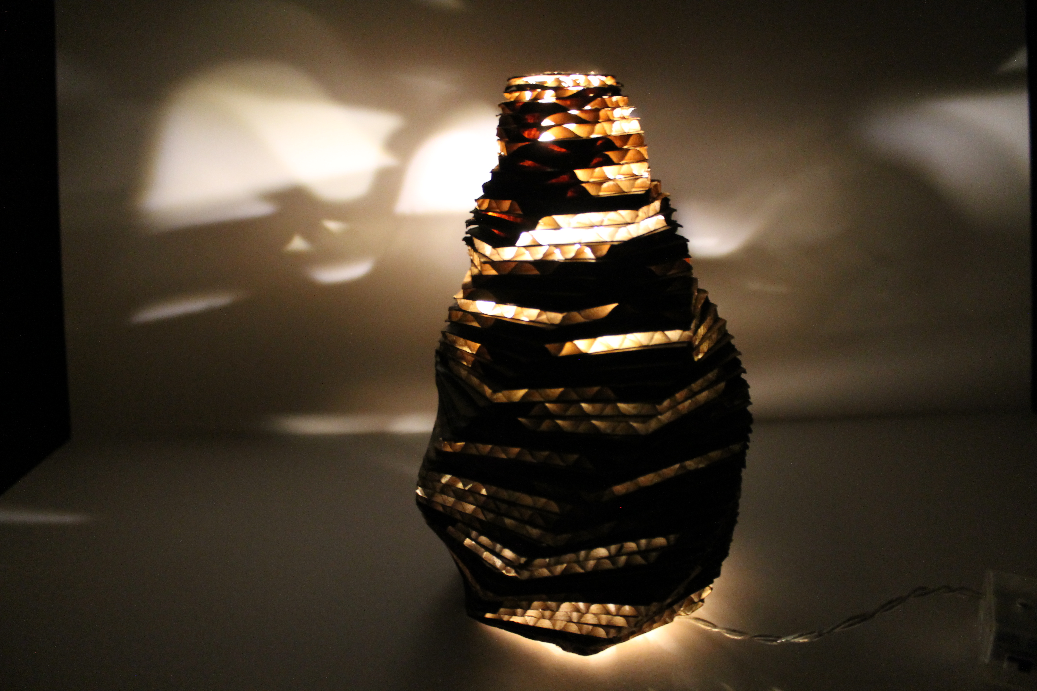
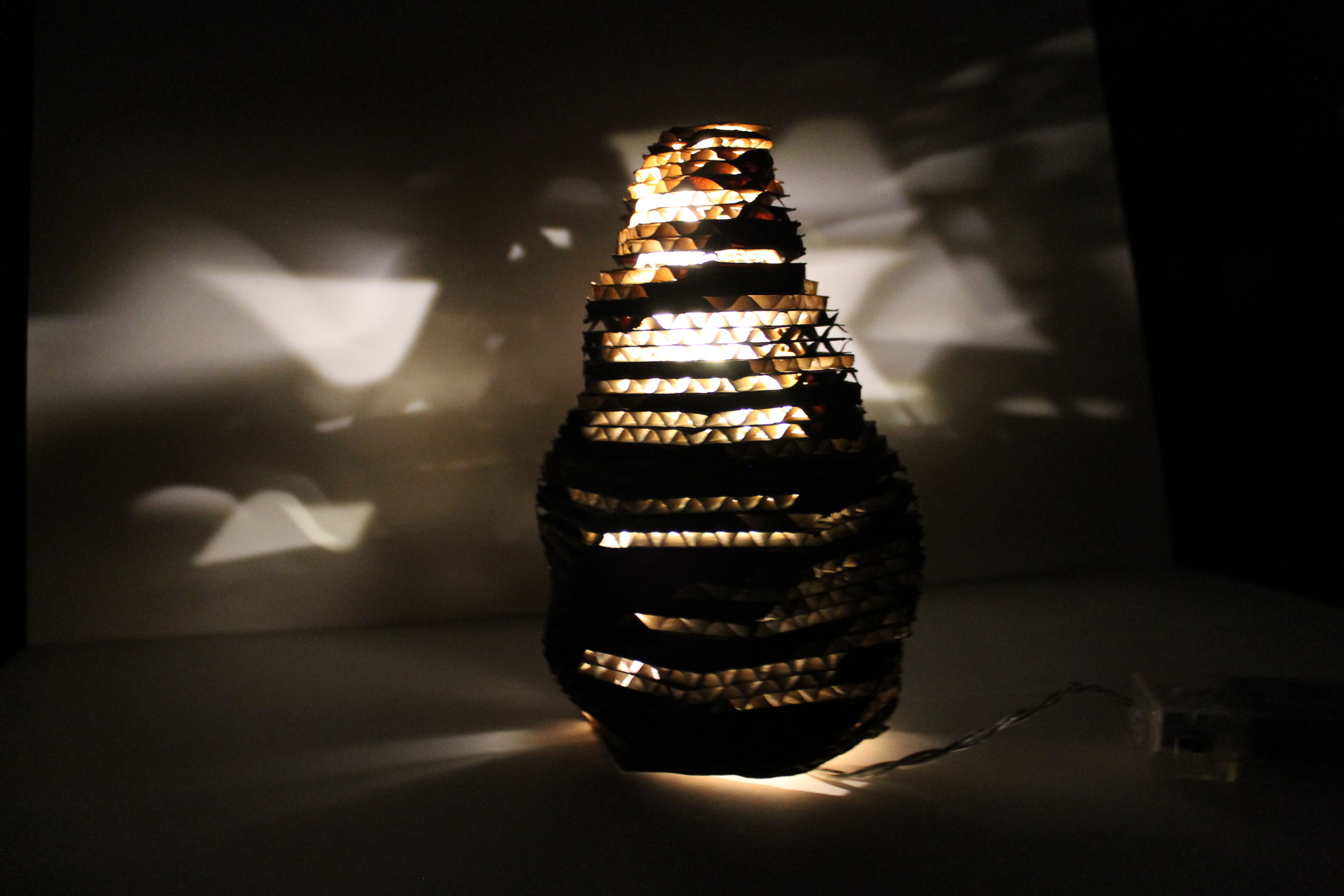
Add some lights and you're all set !!
Hope you enjoyed it. Share some feedback and let me know what other things you would like to make using parametric design. Have fun !!!!