Laser Plotter: Sending the Drawing in GCODE
by Fernando Koyanagi in Workshop > CNC
5778 Views, 19 Favorites, 0 Comments
Laser Plotter: Sending the Drawing in GCODE

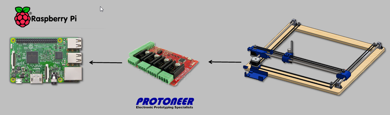
While continuing the Plotter and Laser project with Raspberry Pi CNC HAT, we finish today the electronic part. Also, I’ll discuss loading and performing a drawing. I really like this setup, especially considering the innovation of using a Raspberry instead of an Arduino. Soon, we will have a fourth video, where we will replace the pen that we have in our example by a laser.
In the first video on this subject, we set up an XY table, which is the basis of this "printer,” which serves both to record and cut certain materials, and involves the whole process of assembly of the mechanical part. In the second video entitled “How to configure CNC with Raspberry Pi” we prepared this microcontroller with the image RPI CNC V4 using HAT version 2.58, and then configured the GRBL. The content in this article and below is for the third video in this series.
I want to highlight that, in addition to replacing the Arduino with Raspberry Pi, in this project we also have the novelty of being able to use a HAT, which is like Shield for Raspberry. It is called the Protoneer (Electronic Prototyping Specialists). See how the project works in a demo in this third video of the series.
Features Used for Table Construction
1 Raspberry Pi 3 (but could be B+, 2, or 3 with 20x2 connection)
1 Protoneer RPi CNC Hat version 2.58
1 16Gb micro SD card (recommended 8GB or more)
1 Source 12V x 10A
3 step motor drivers DRV8825
1 Monitor with HDMI or with an adapter
USB Keyboard and Mouse
Wires, soldering iron, soldering
Completing the Electronics
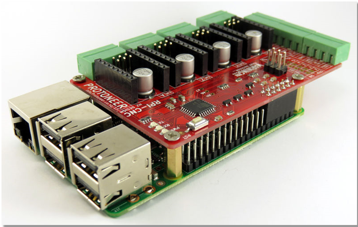
So far, we set up the CNC Hat RPi on Raspberry, but without making any connections to the drivers, motors, and sensors. Before proceeding, we must not forget to properly shut down the operating system (shutdown) and, after its completion, disconnect the power supply assembly.
Completing Electronics - Drivers
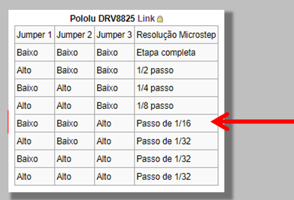
Let's start by adjusting the resolution of the steps we will use. We chose to use the DRV8825 driver with 1/16 pitch.
Between the connectors of each driver, there are three jumpers numbered 1 to 3. These are responsible for this configuration. For the Pololu DRV8825 driver, the manufacturer's table indicates that only pin 3 must be enabled.
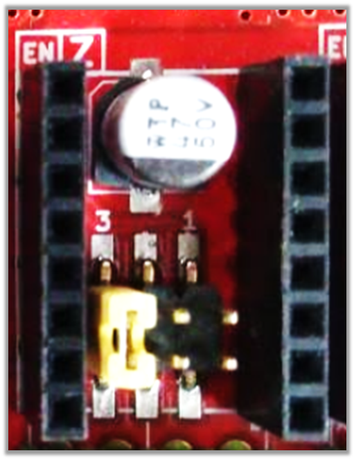
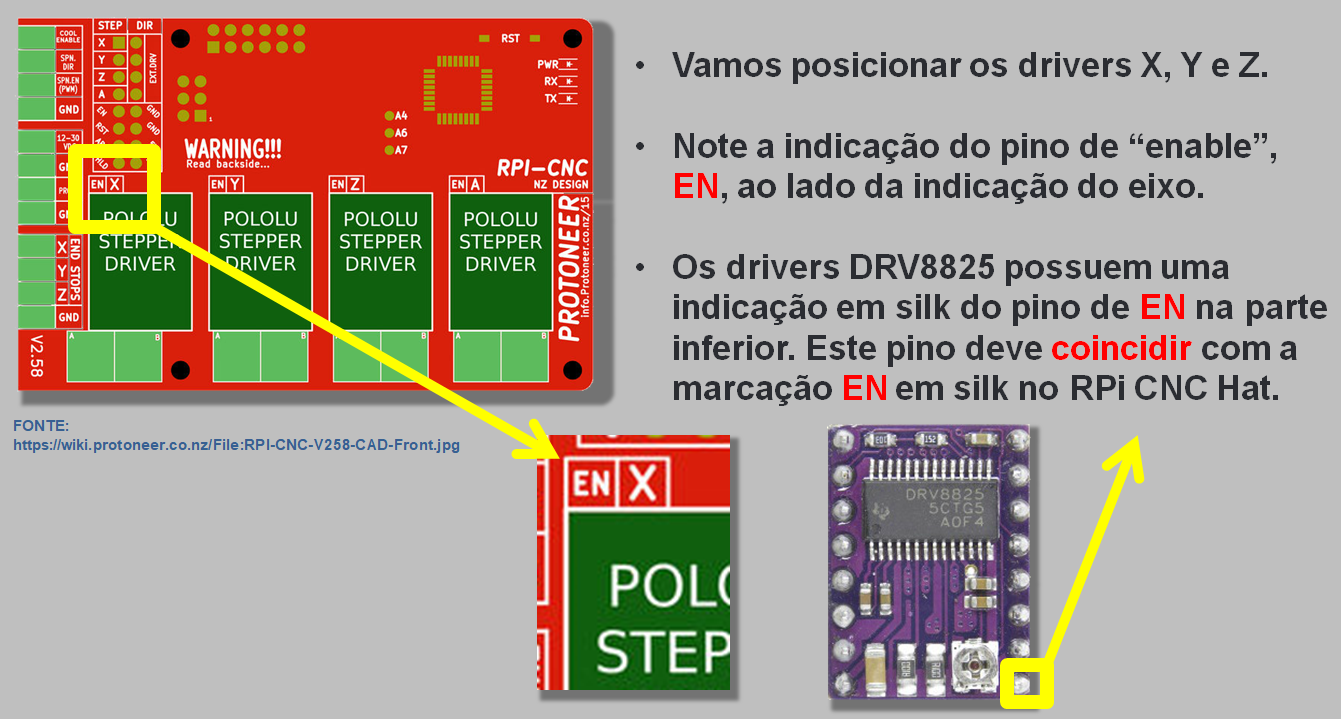
Let's position the X, Y, and Z drivers. Note the "enable" pin, EN, next to the axis display.
The DRV8825 drivers have a silk indication of the EN pin at the bottom. This pin should match the EN mark in silk on the CNC Hat RPI.
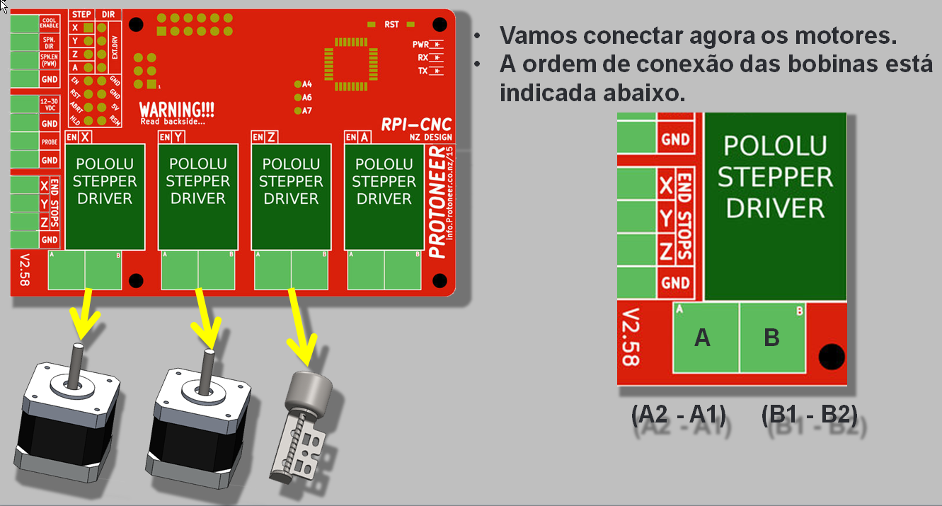
We will now connect the motors, and the order of connection of the coils is shown in image.
Completing the Electronics - Limit Sensors
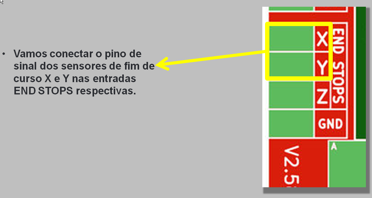
We will connect the signal pin of the X and Y limit sensors to the respective END STOPS inputs.
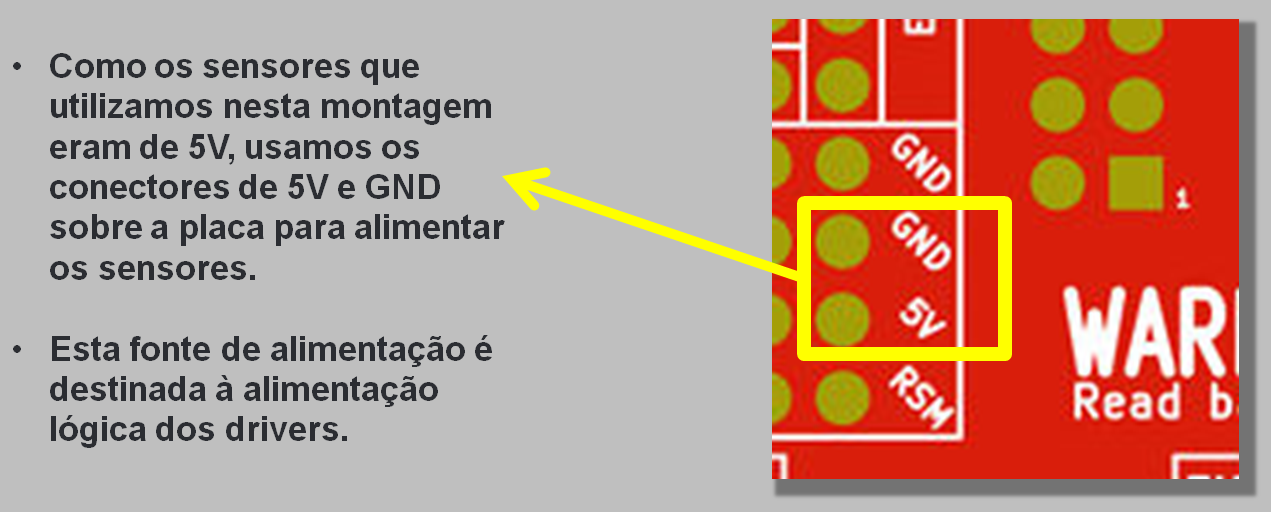
Since the sensors we used in this setup were 5V, we used the 5V and GND connectors on the board to power the sensors.
This power supply is intended for the logical power supply of the drivers.
Completing Electronics - Food
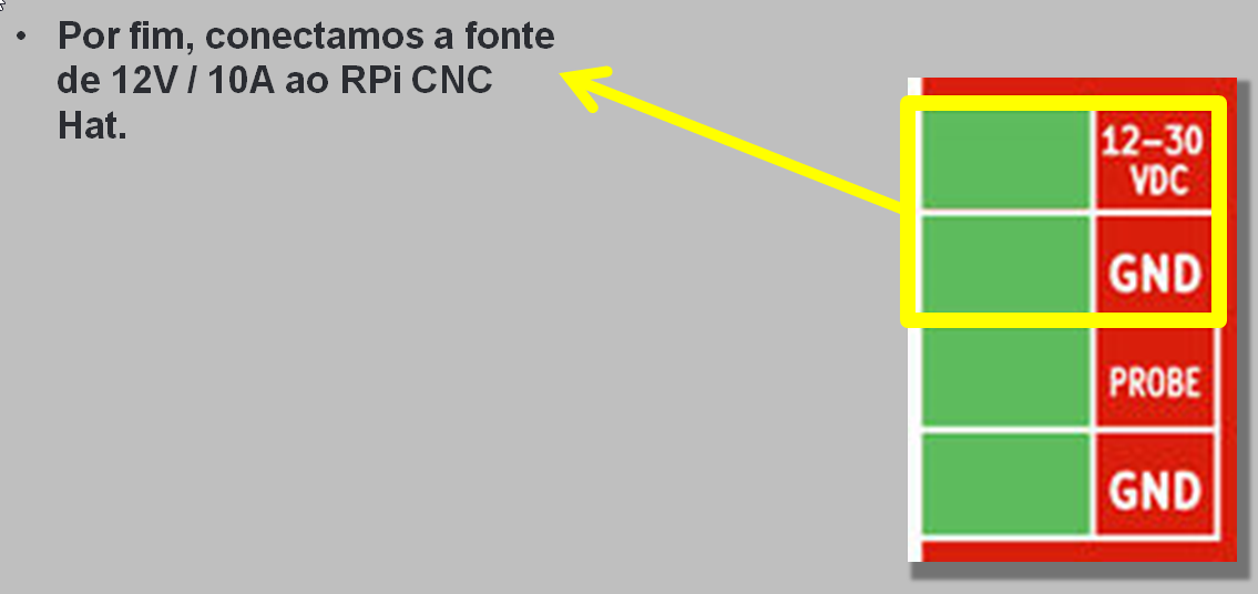
Finally, we connected the 12V/10A supply to the CNC Hat RPi.
Completing the Electronics - Setting the Motor Current Limit
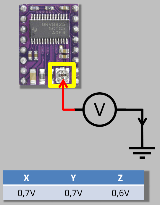
We now need to adjust the current limits for the motors. On each DRV8825 driver, we will find a potentiometer for adjusting this limit.
Using a voltmeter, we can measure the voltage at the cursor of this potentiometer relative to the ground.
For each driver we use the following values, shown in the table.
Generating a File for Printing

Generating a file - Inkscape
1
To generate G-Code files, an interesting option is to use InkScape with the extension "GCodeTools".
We will not delve into all the available options, but instead, we’ll pass to you a quick guide to import an image and generate a file.
InkScape can be found for download at https://inkscape.org/.
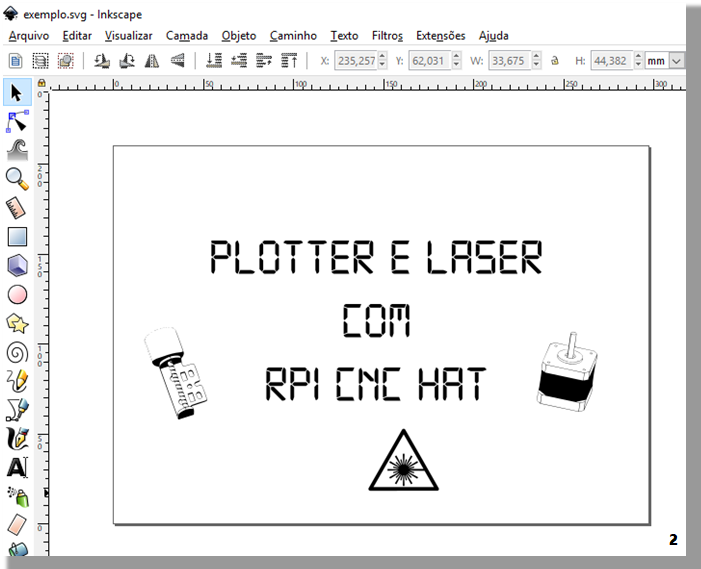
2
Start by importing an image or use InkScape to draw it.
It is important that all objects in your drawing are converted into paths before proceeding with G-Code generation. (shift + ctrl + C) or in the "Path" menu.
You can also drag a bitmap image to use. To do this, go to the menu "Path" or (shift + alt + B).
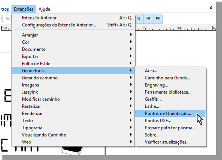
3
After finishing editing your image, we will prepare the settings to generate the G-Code.
Access the menu:
Extensions >> Gcodetools >> Guidance Points
This function will create reference points and scale for the generated G-Code.
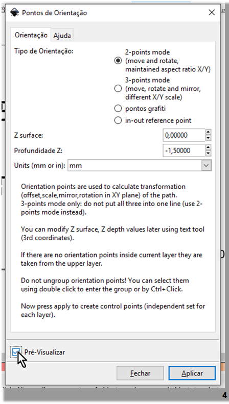
4
Let's use the first option: "2-points mode"
We mark the depth Z as -1.5mm. This will be the final depth of the tip of the pen.
We left the unit in millimeters.
We click on "Apply" so that landmarks are created.
5
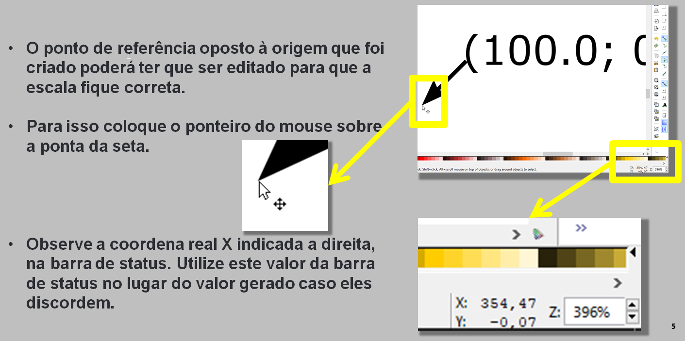
The reference point on the opposite side of the origin that was created may have to be edited in order for the scale to be correct. To do this, place your mouse pointer over the arrowhead.
Notice the actual X coordinate shown on the right in the status bar. Use this value of the status bar in place of the generated value if they disagree.
6
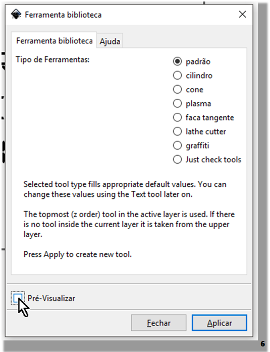
After adjusting the reference points, access the menu again:
Extensions >> Gcodetools >> Library tool
For our example, we will select the "standard" tool and click apply.
7
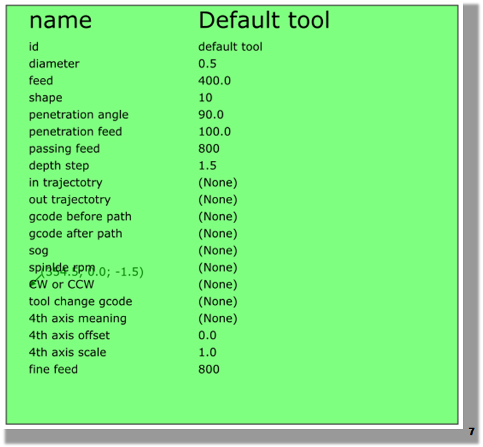
A green frame like the one shown here should appear.
Let's edit two values:
Diameter: We will use 0.5mm as the diameter of the tip of the pen.
Depth step: We will use 1.5 for the drawing to be performed in a single step.
8
Given the tool, we will access the menu:
Extensions >> Gcodetools >> Path to G-Code
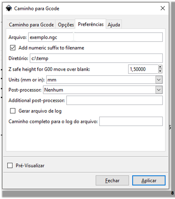
In the "Preferences" tab, we can specify the name of the file and the directory where it will be saved.
We must also determine the safe height for the Z-axis as the pen moves from one point to another without drawing. In this case, we use 1.5mm.
We must also select the unit. In our case, this will be millimeters.
9
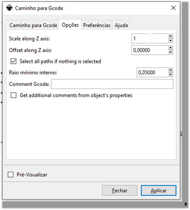
In the "Options" tab, we check if the Z scale is in "1" (Scale along Z axis).
10
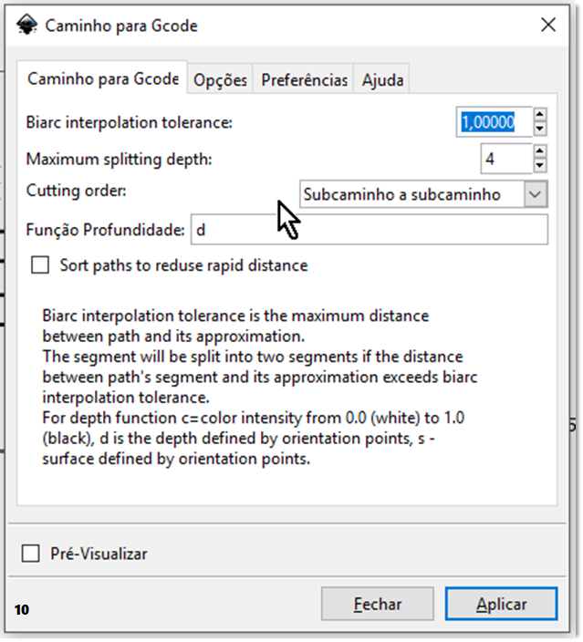
And, finally, in the "Path to G-code" tab, we leave it as default.
We click apply and wait while the G-Code file paths are generated.
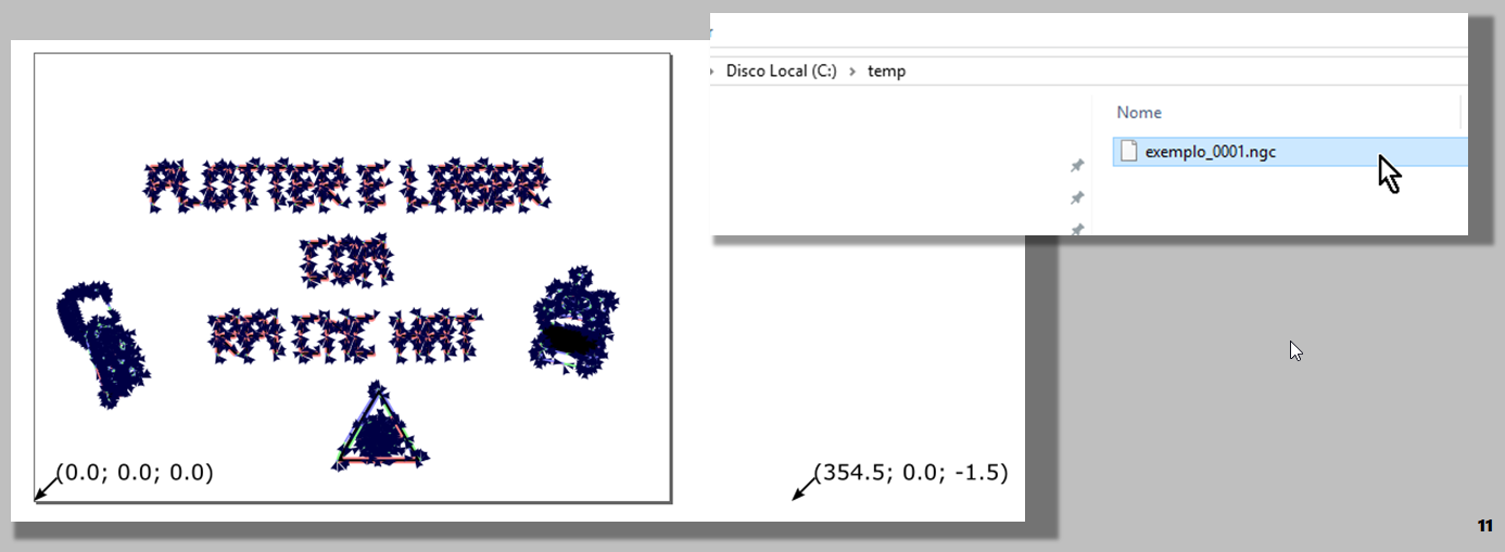
If something goes wrong, look at the error message because it should indicate possible solutions, especially if some object can’t be converted to path.
11
If everything is correct, you will be able to see the paths (represented by blue arrows) throughout the drawing. Then a file will be generated in the chosen directory.
Using BCNC to Print the File
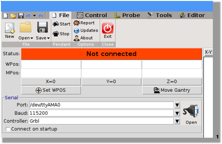
1
Open the bCNC and, in the "File" menu, open the connection with the Hat.
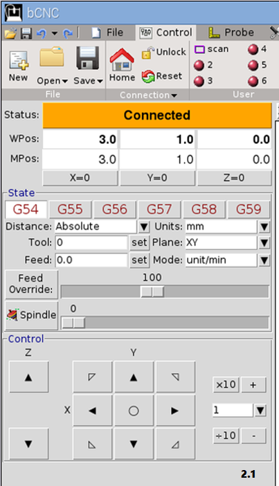
2
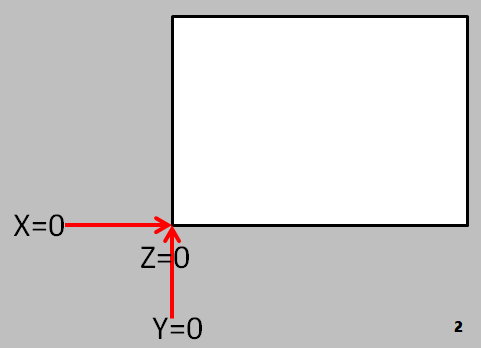
In the "Control" menu, use the controls to position the pen tip in the lower corner of the sheet of paper.
After positioning, use the X = 0, Y = 0, and Z = 0 buttons to determine the origin.
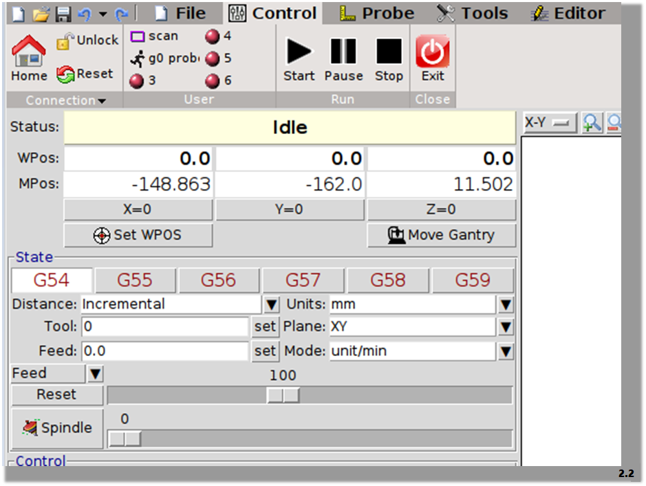
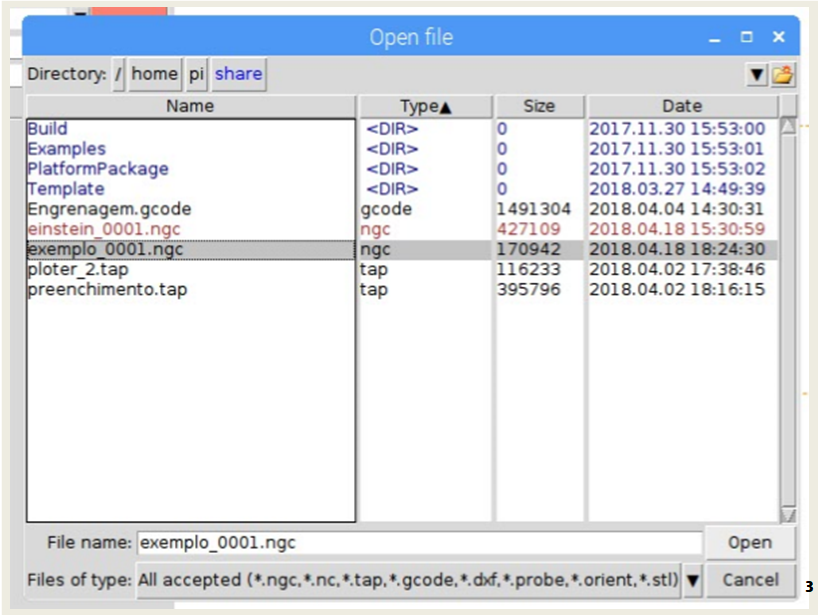
3
In the "File" menu, click "Open" and select the file for printing.
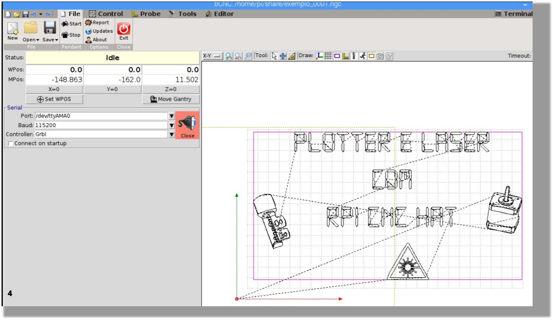
4
You should be able to view the paths that will be printed.
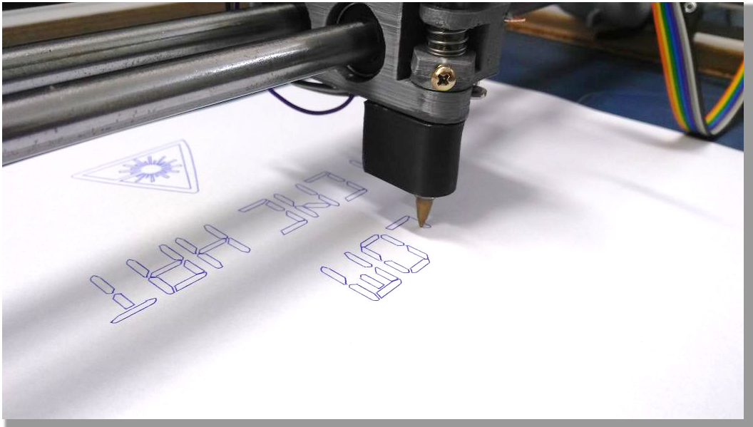
It’s important to remember that when you put a pen in the plotter, it is different from using a laser or a spindle. So, knowledge concerning how to tinker with a router, a cutter, or a laser engraver is essential for this assembly, as well as just being simple and safe.