Laser Etched Paper for Folding Complex Forms
by andreasbastian in Workshop > Laser Cutting
32930 Views, 250 Favorites, 0 Comments
Laser Etched Paper for Folding Complex Forms
.JPG)
.JPG)
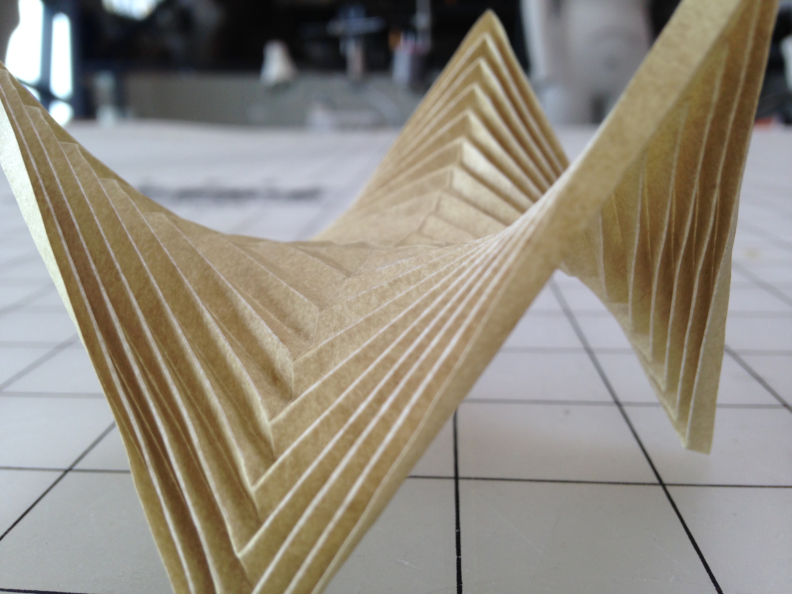
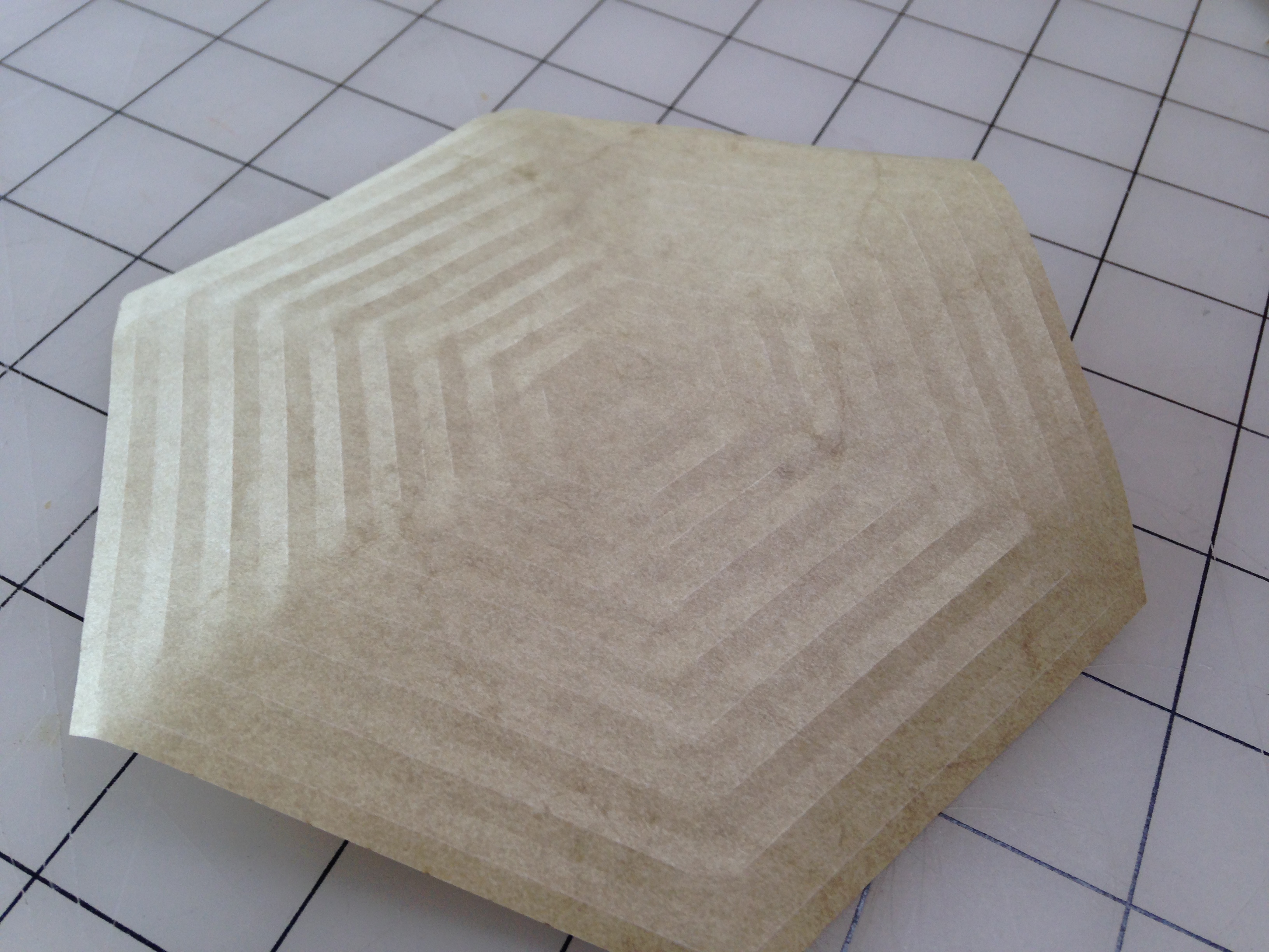
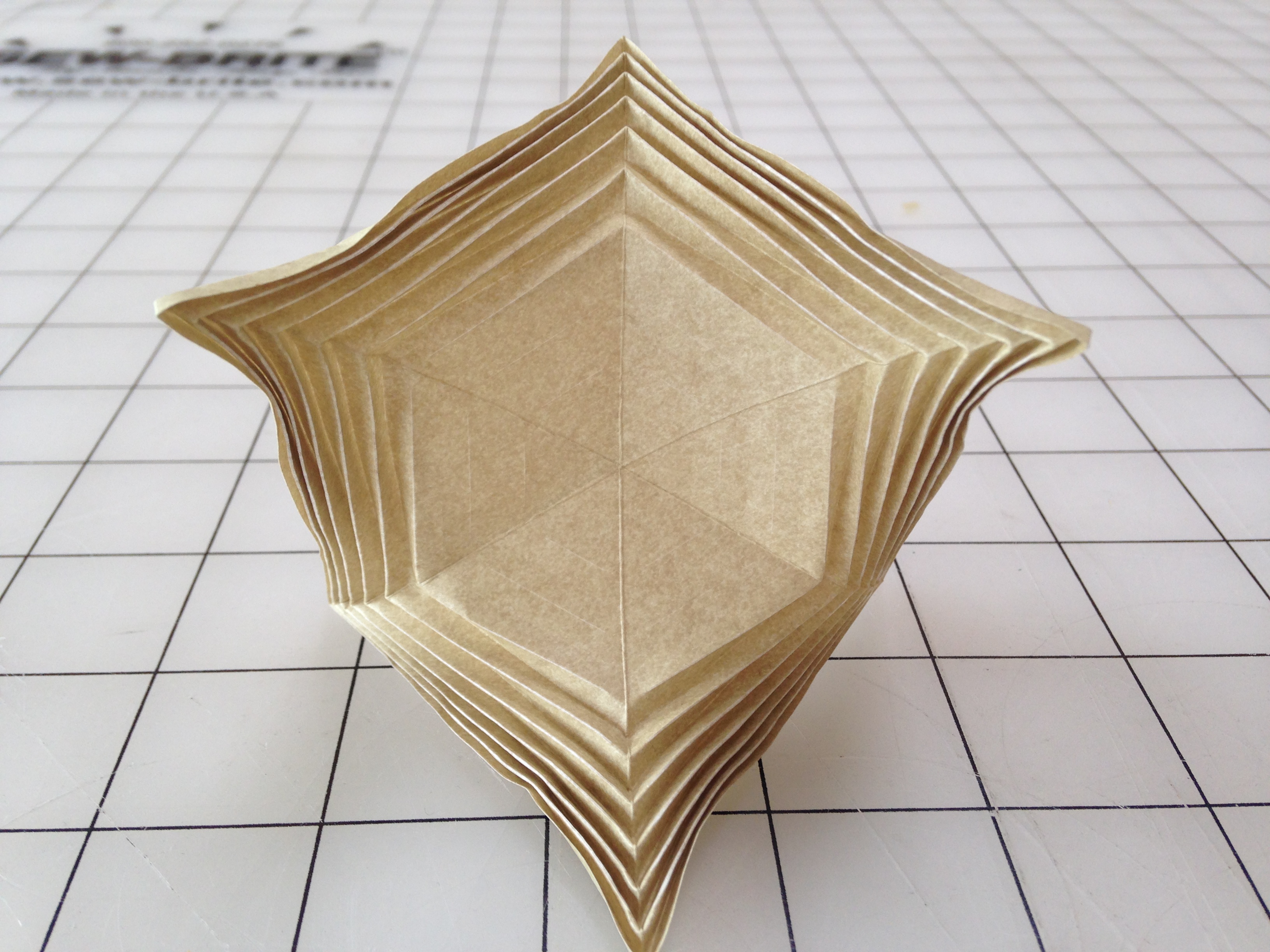
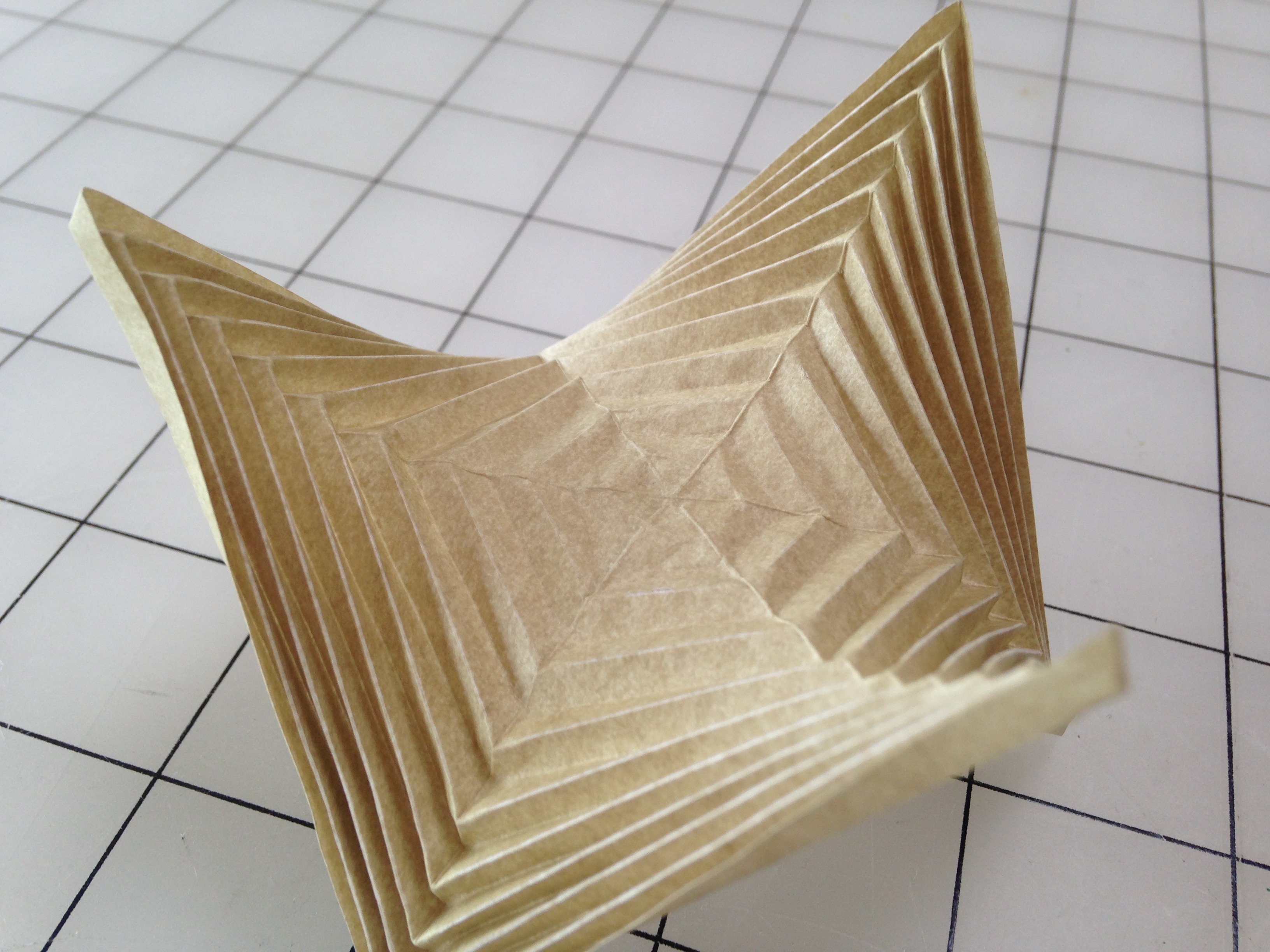
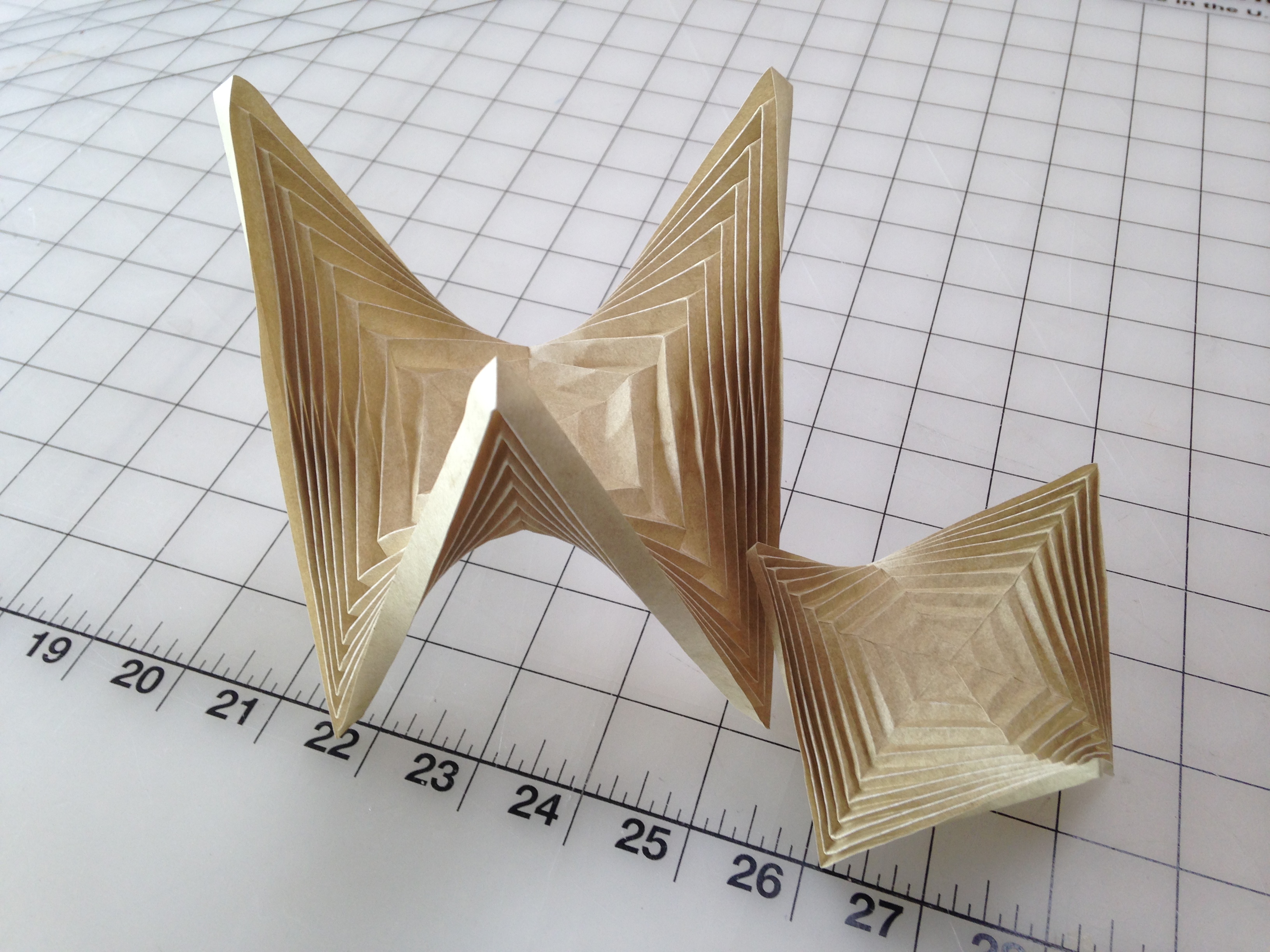
Folding is a powerful tool for both aesthetics and engineering. Many forms are possible using folding techniques, but it becomes increasingly difficult to attain these forms as the crease paths develop more and more complexity and density. By laying out all the folds in software and laser etching the two sides of a piece of paper, much more complex forms become possible. Described here is a method for laser etching elephant hide paper on an Epilog Legend EXT 100 Watt laser cutter to facilitate the complex folds that compose a hexagonal hyperboloid.
Prepare Your Files
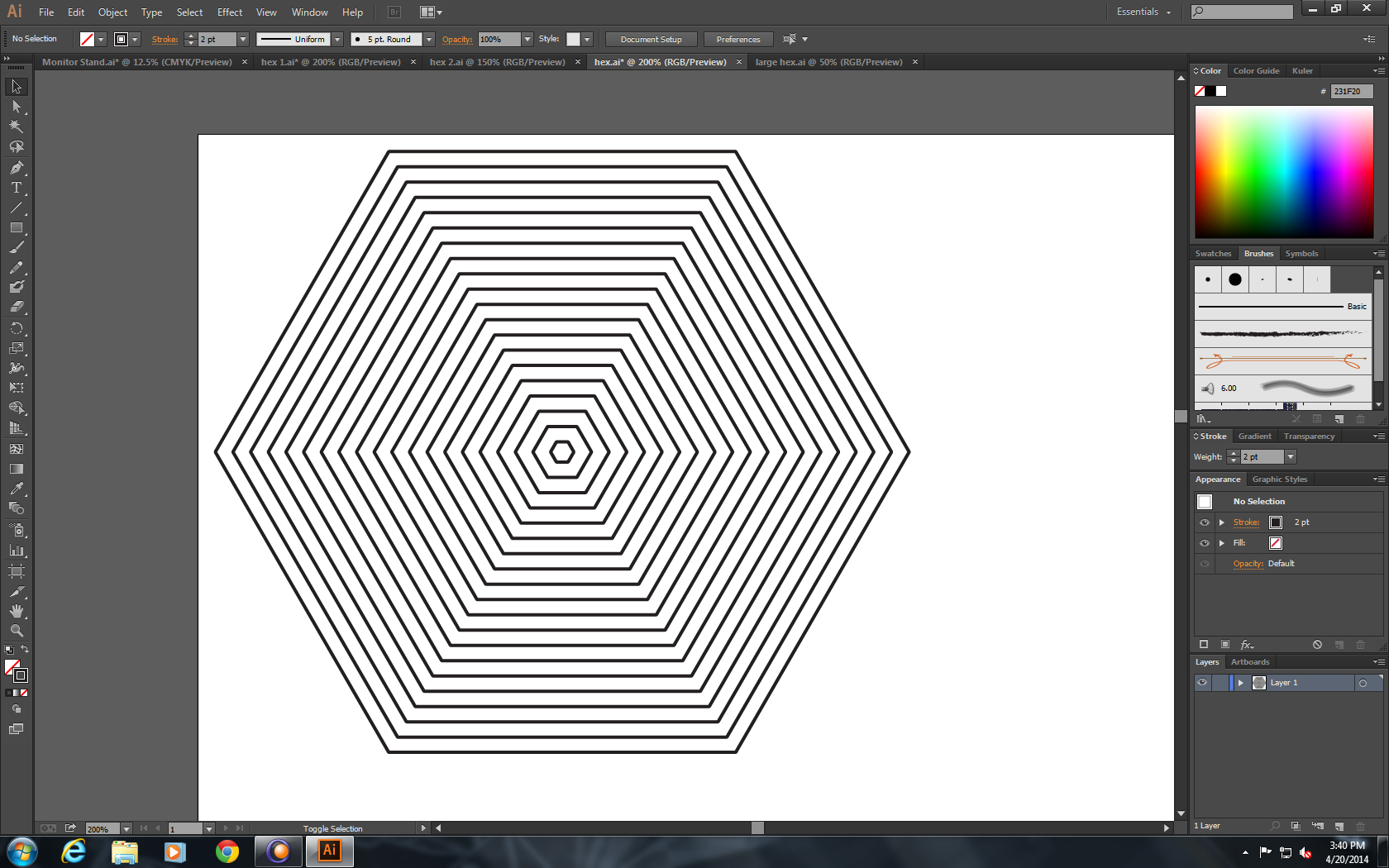
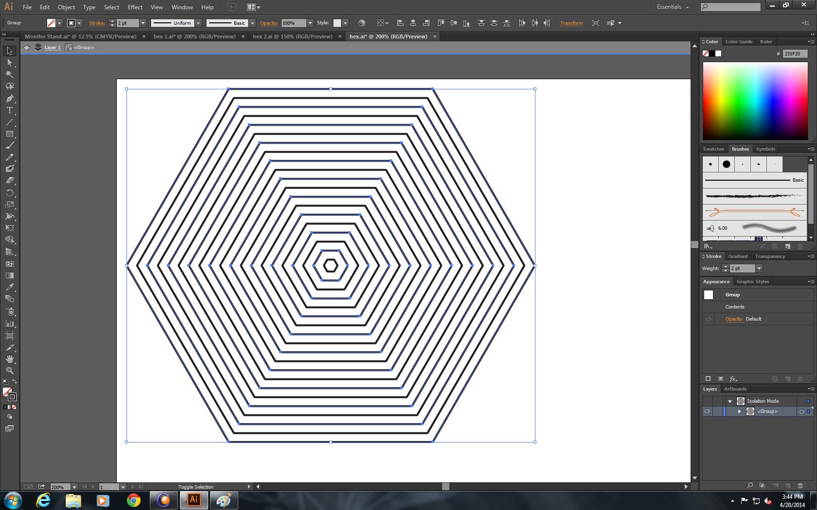
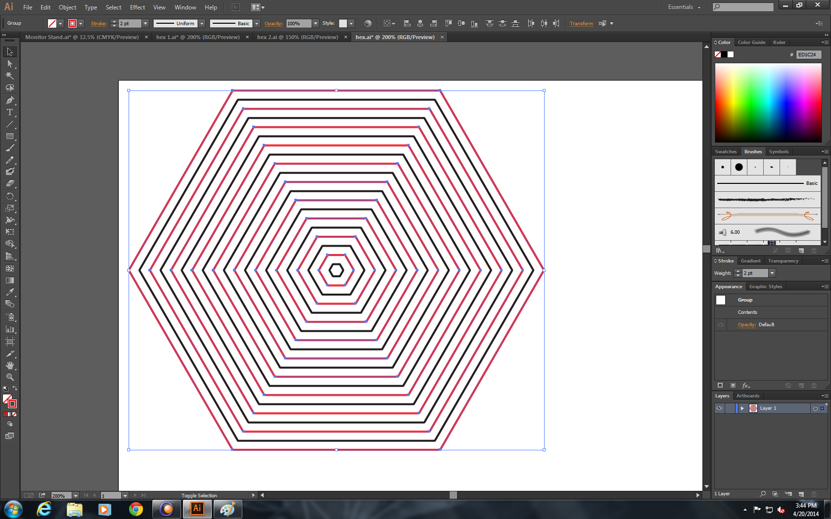
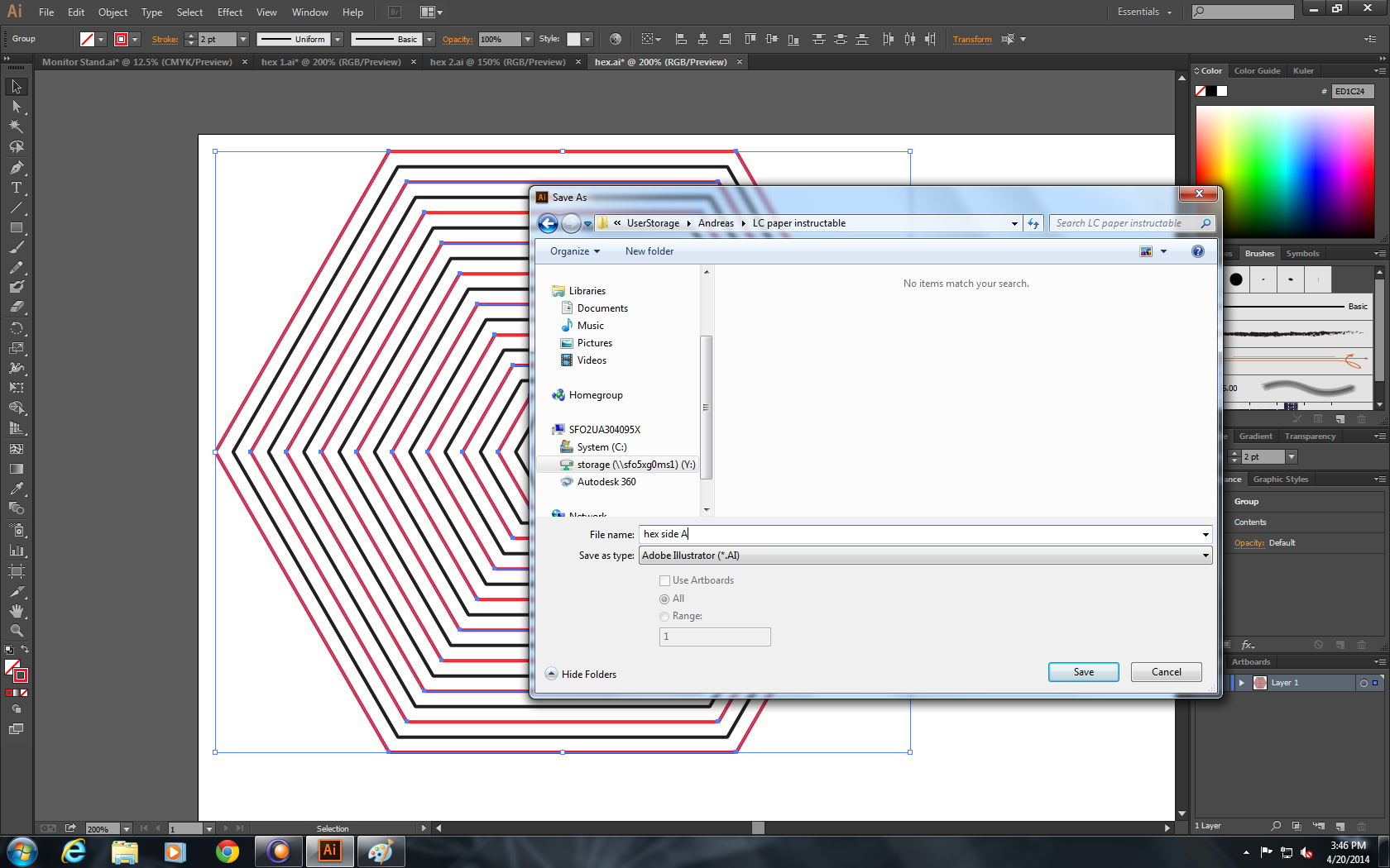
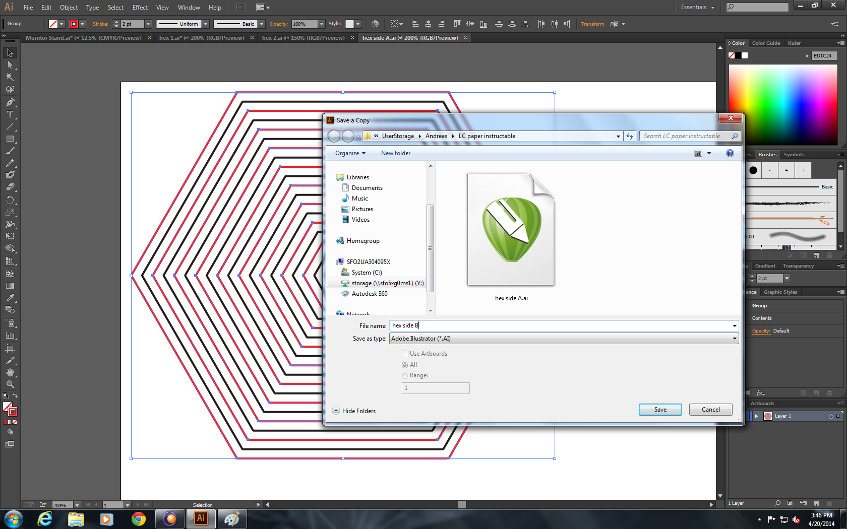
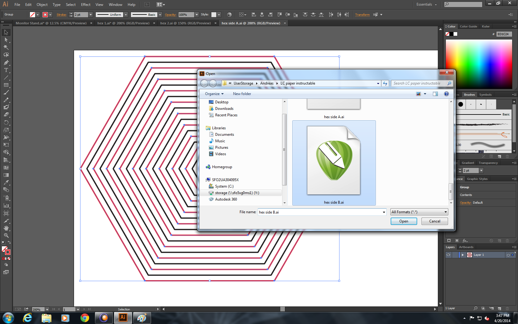
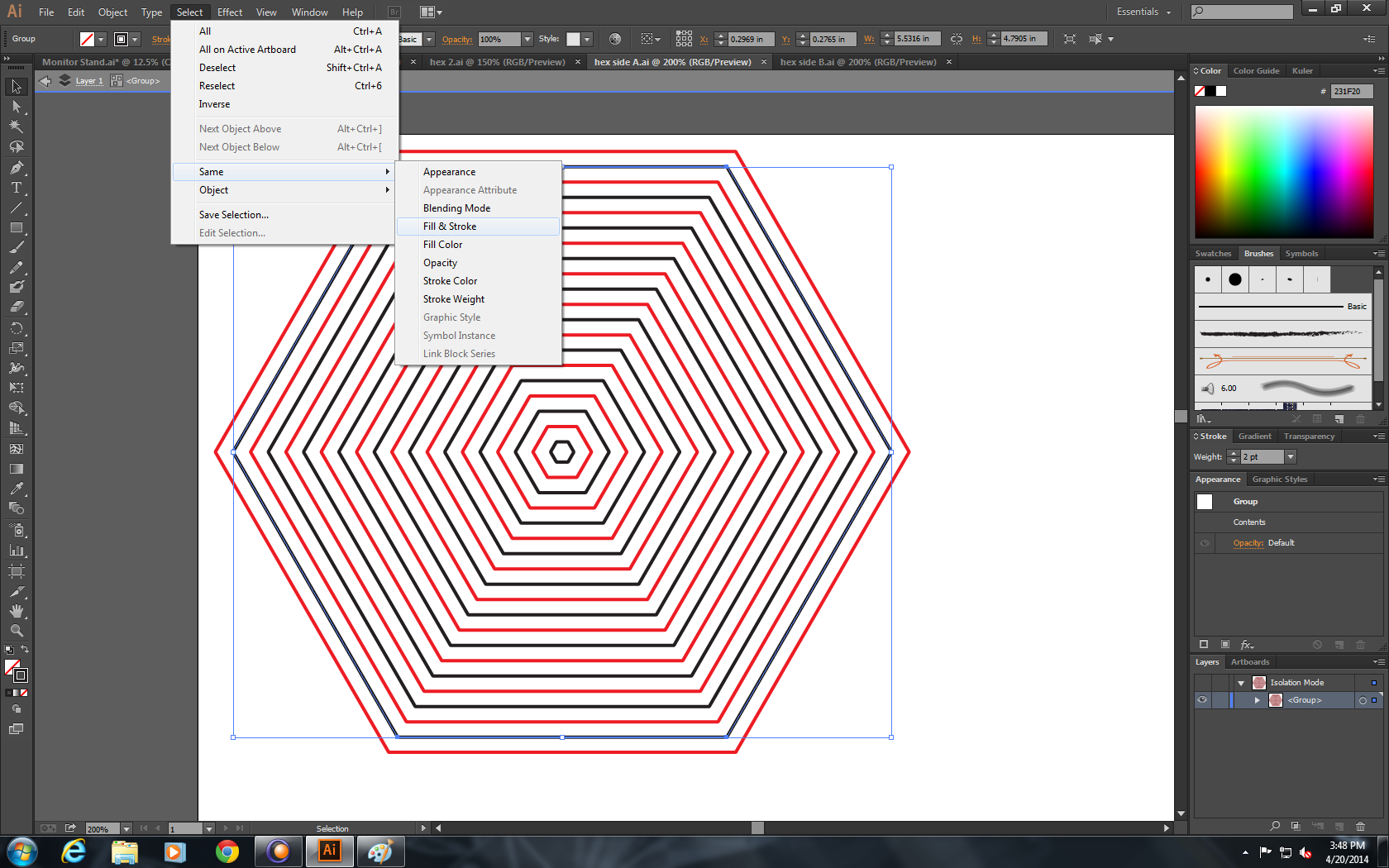
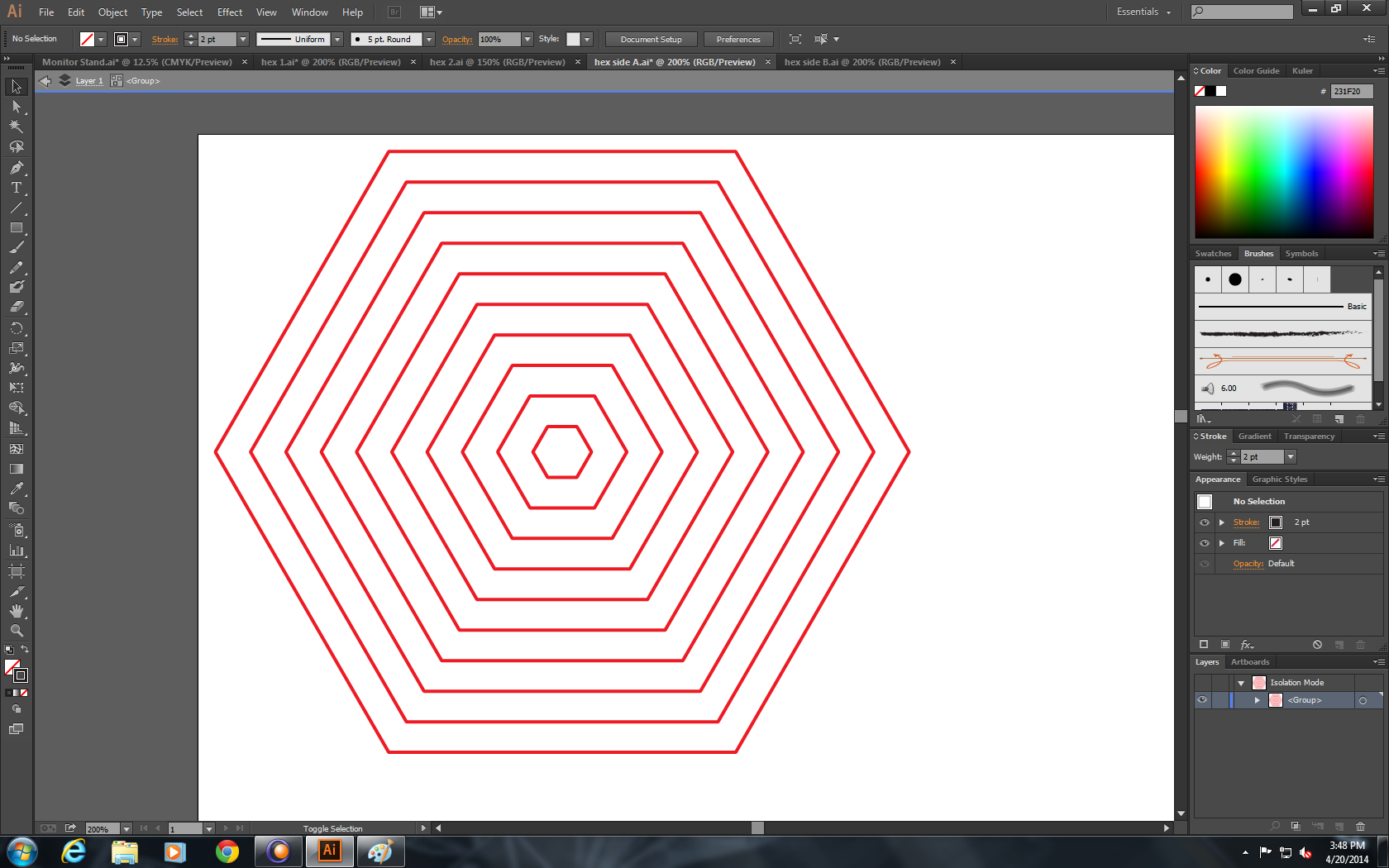
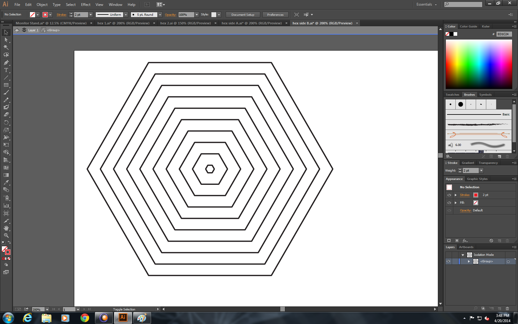
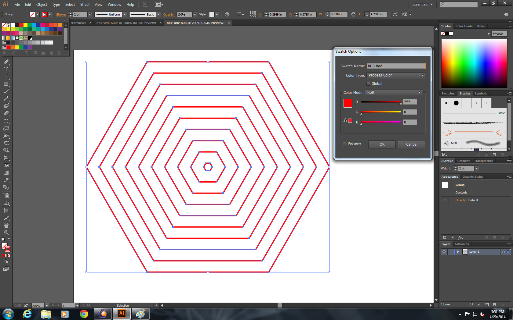
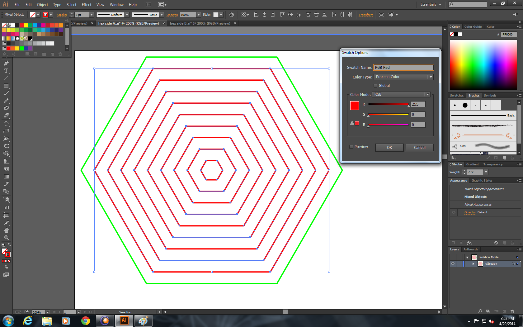
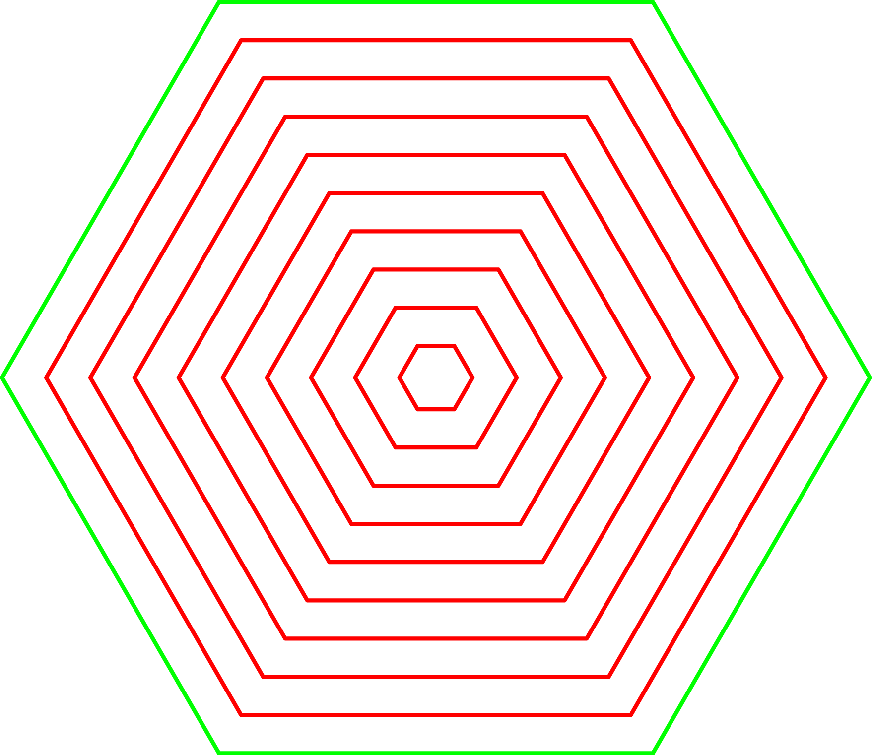
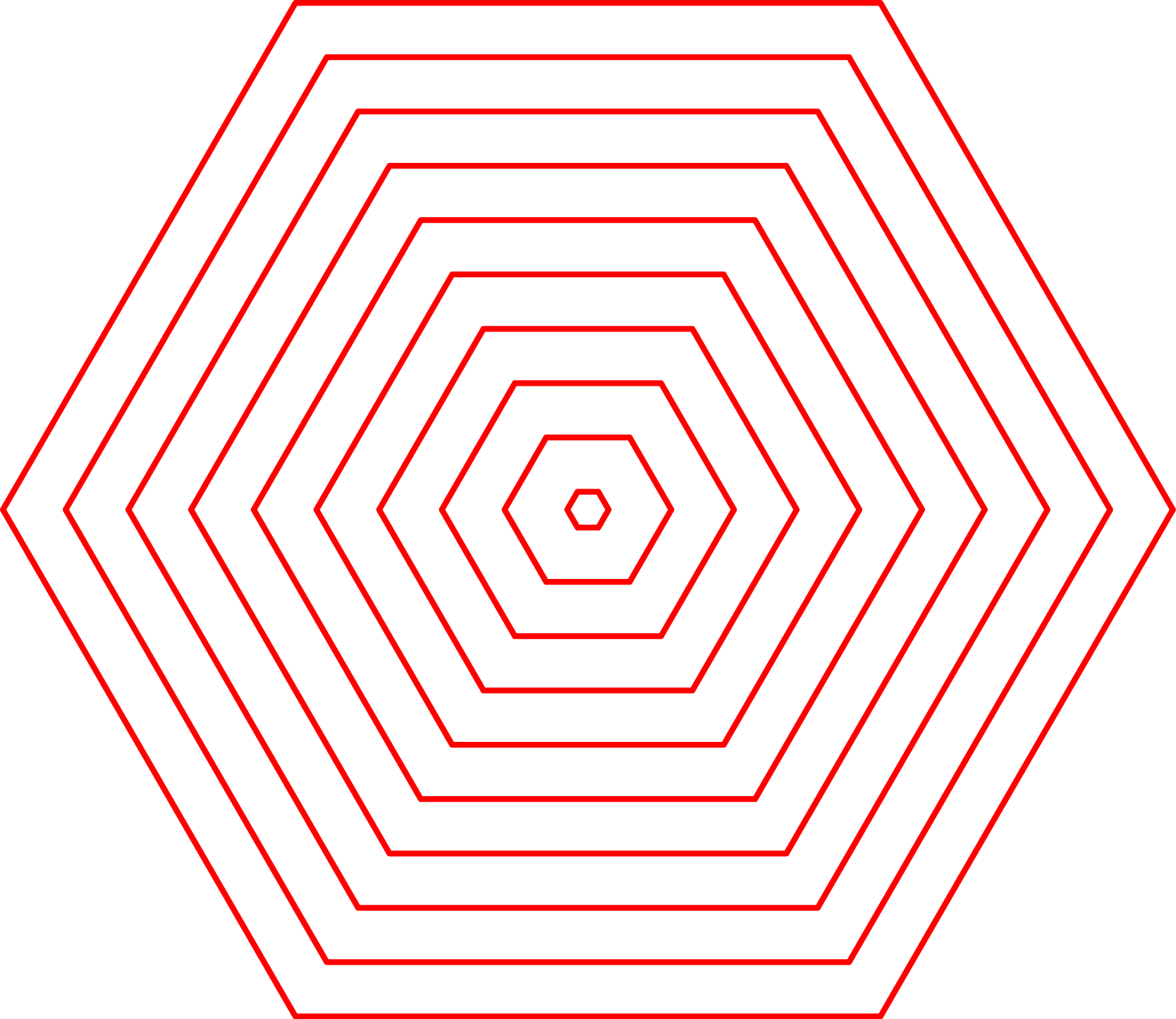
There are a lot of different ways to lay out your fold paths. I used Autodesk Inventor to lay out a very simple set of concentric hexagons to create a hexagonal hyperboloid form. For simple forms, I recommend laying out all fold paths (both mountain and valley) in the same file (using different layers if your software has the capability to), which makes alignment easier later in the process. You can also separate your mountain and valley folds from the beginning if you choose. For this example, I started with all folds in one file.
- Import your fold paths.
- Select your all your mountain folds and change the stroke color.
- Save two copies of your source file: one for mountain folds (side A) and one for valley folds (side B). By creating both fold files form the same source file, you preserve the alignment and location of both sets of crease paths.
- In your side A file, delete all the valley folds (black lines) selecting a valley fold and clicking "Select -> Same -> Fill & Stroke".
- Likewise, in your side B file delete all the mountain folds (red lines).
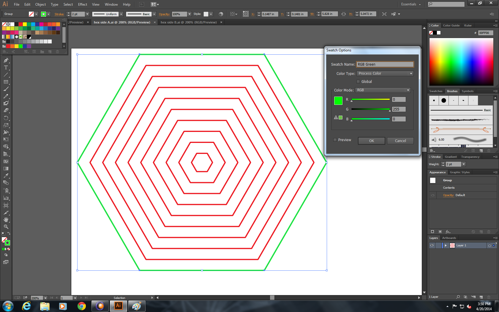
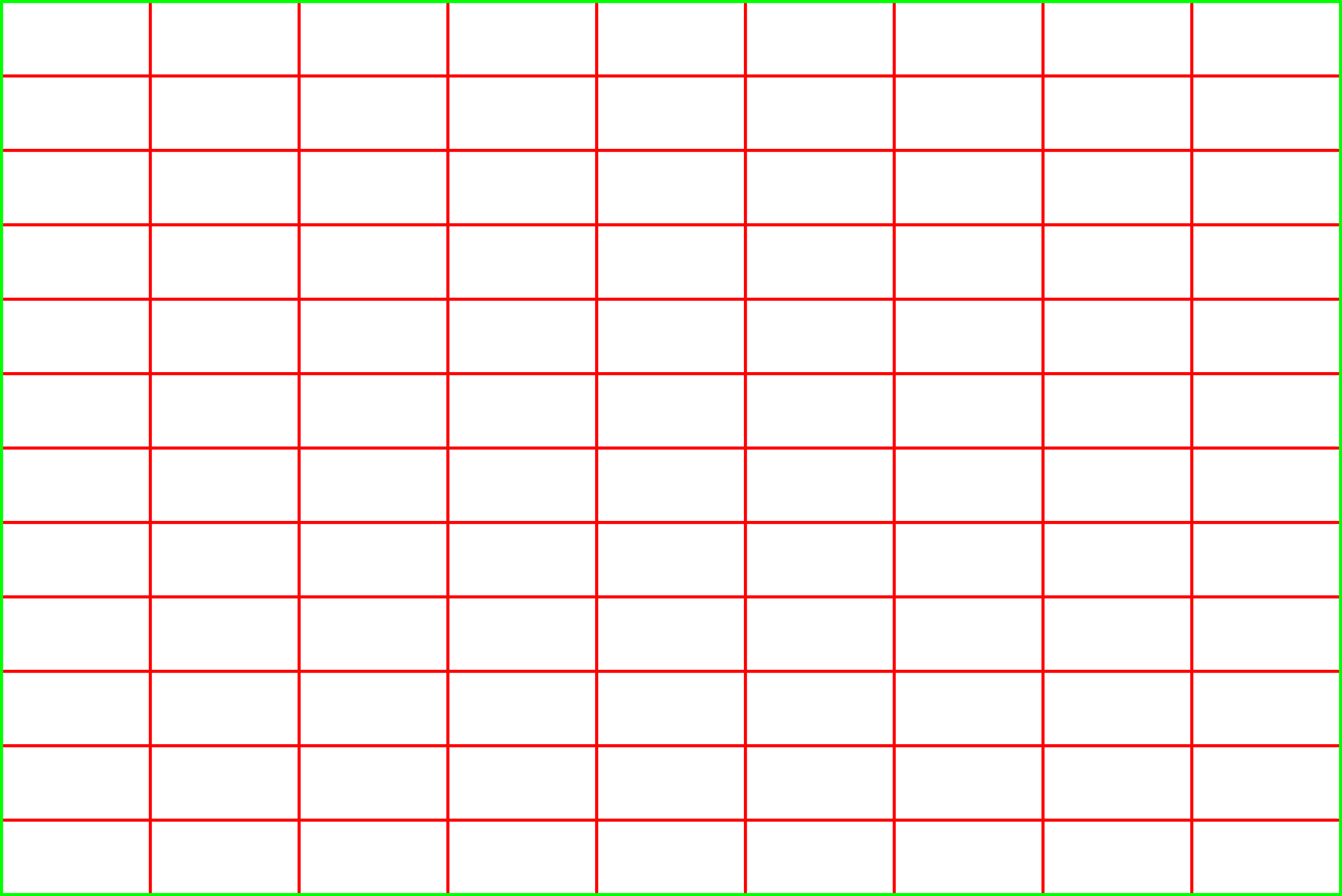
- In the side A file, select the outer-most path and set it to RGB Green (0,255,0), which will be the "cut" color. Set the rest of the paths to RGB Red (255,0,0), which will be the "etch" color.
- In the side B file, set all the paths to the "etch" color (RGB Red).
Prepare to Laser Etch
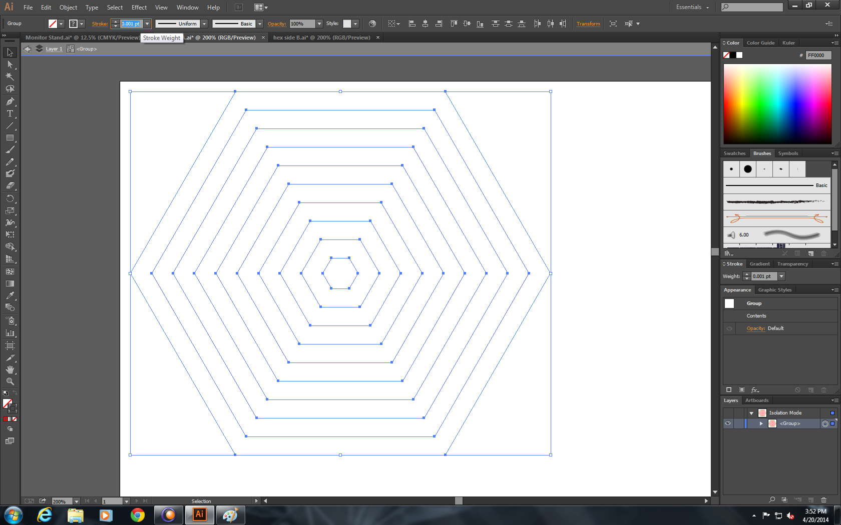
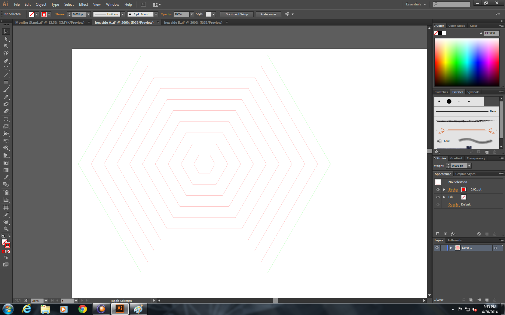
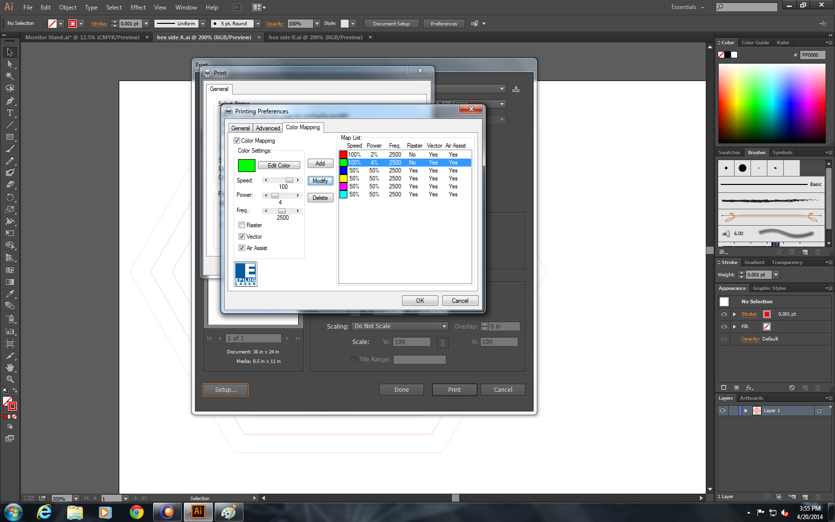
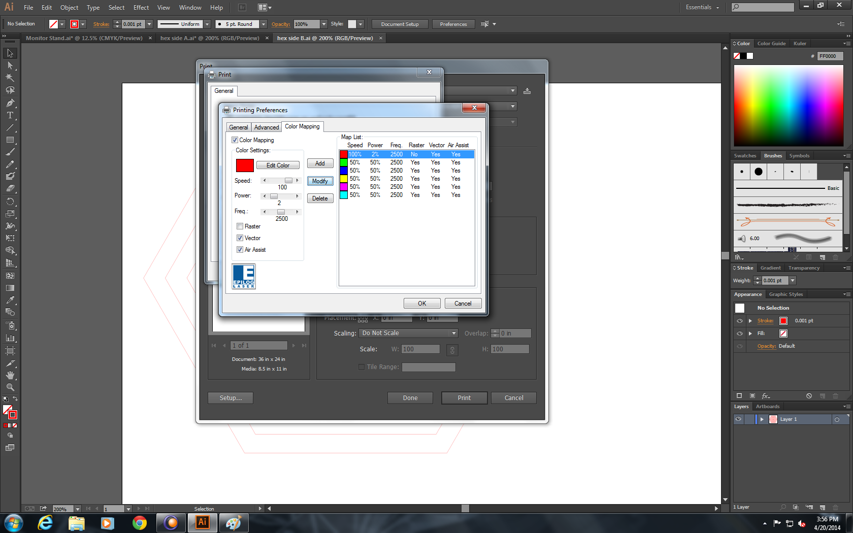
- Set the stroke weight to 0.001pt on both files.
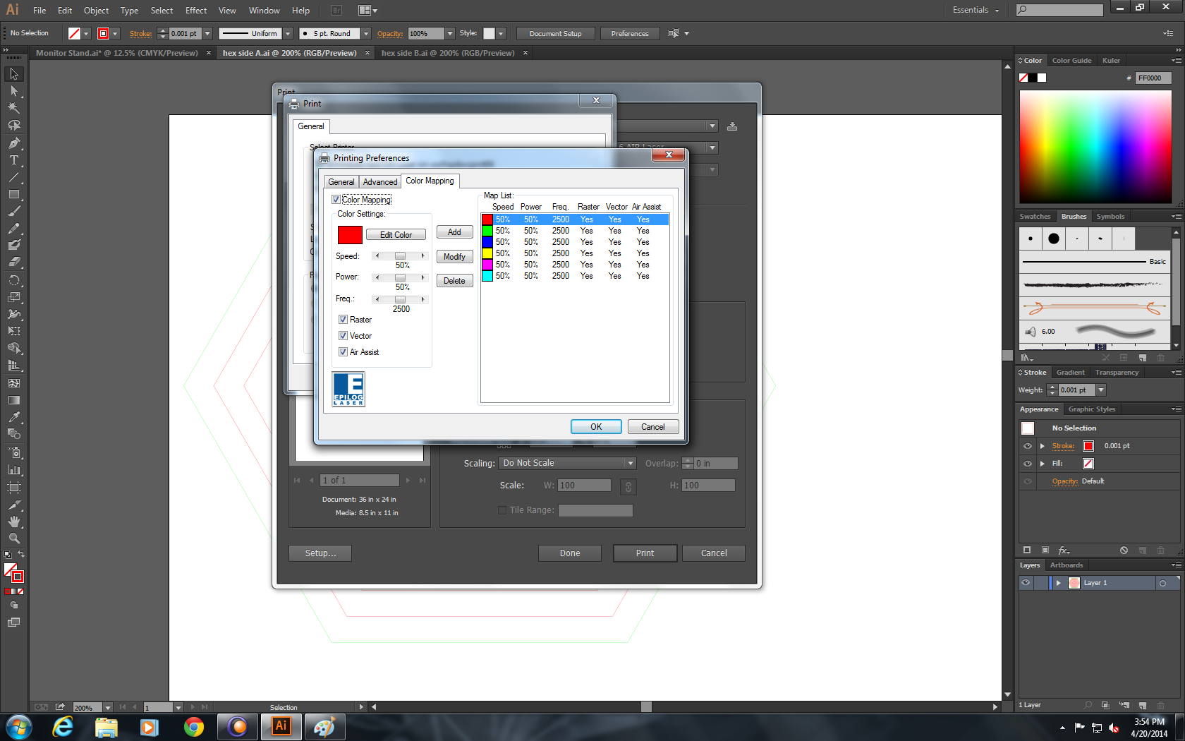
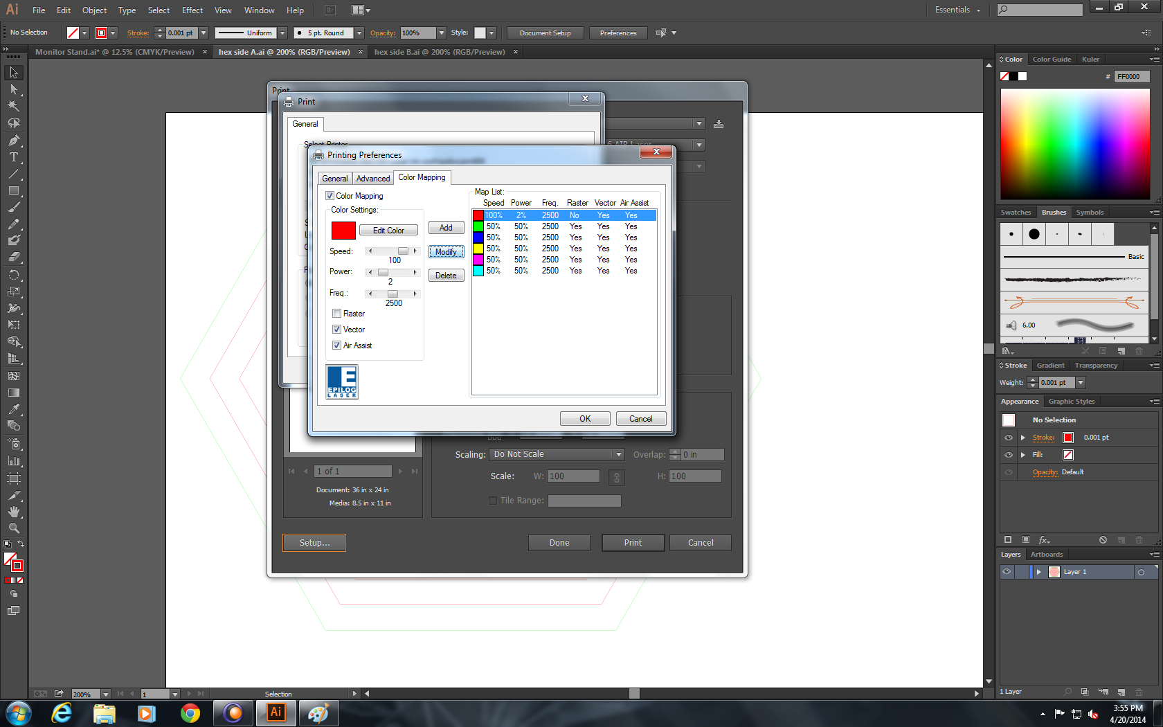
- Enable color-mapping and set the laser power and speeds to the best etch and cut settings for your paper. These valuse should be experimentally determined brand/type of laser cutter. An etch setting of 2% power, 100% speedand a cut setting of 4% power, 100% speed both work well for the Epilog Legend EXT 100 Watt laser cutter that I used.
- Send the files to the laser cutter.
Load the Paper
.JPG)
.JPG)
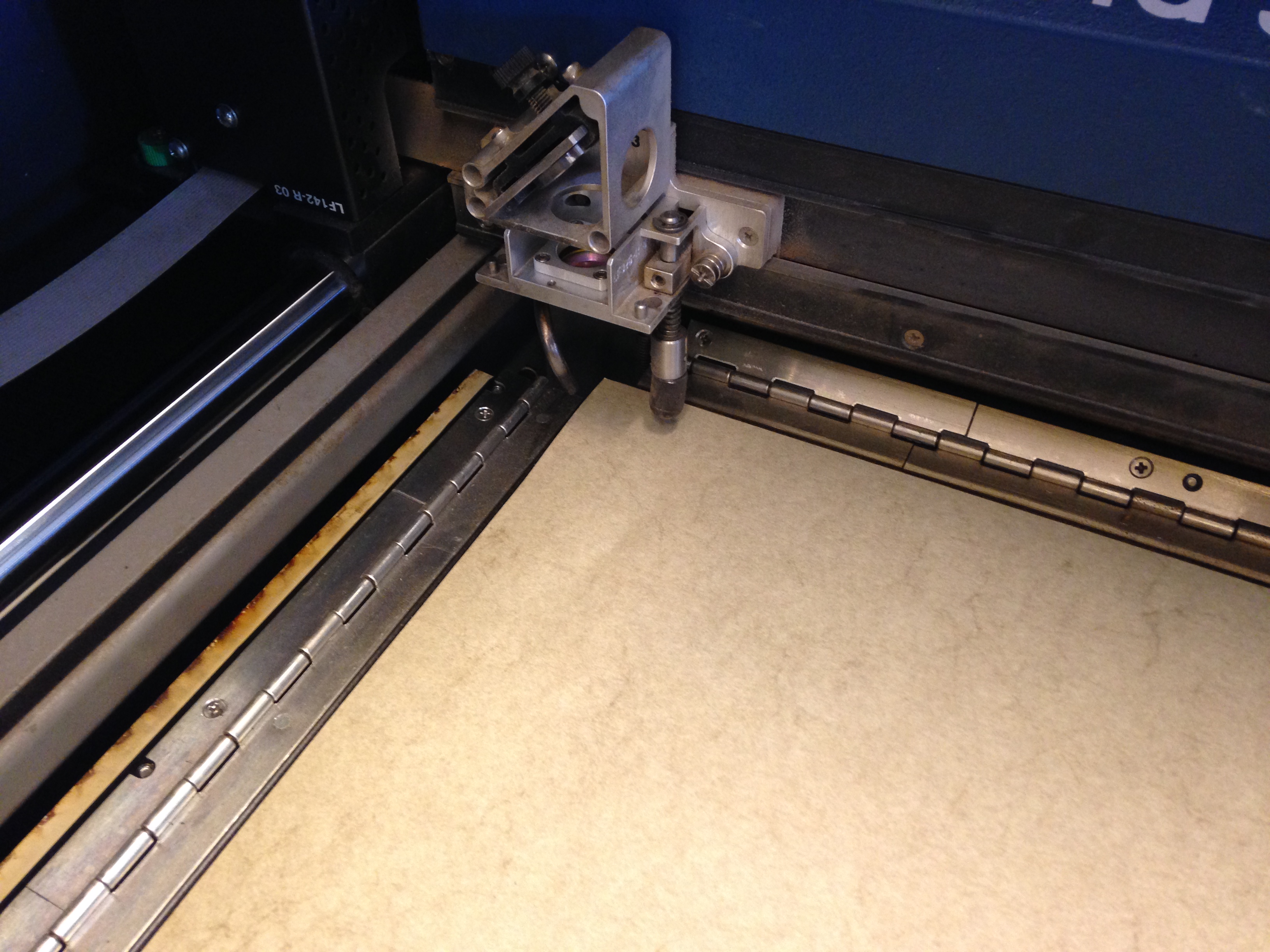
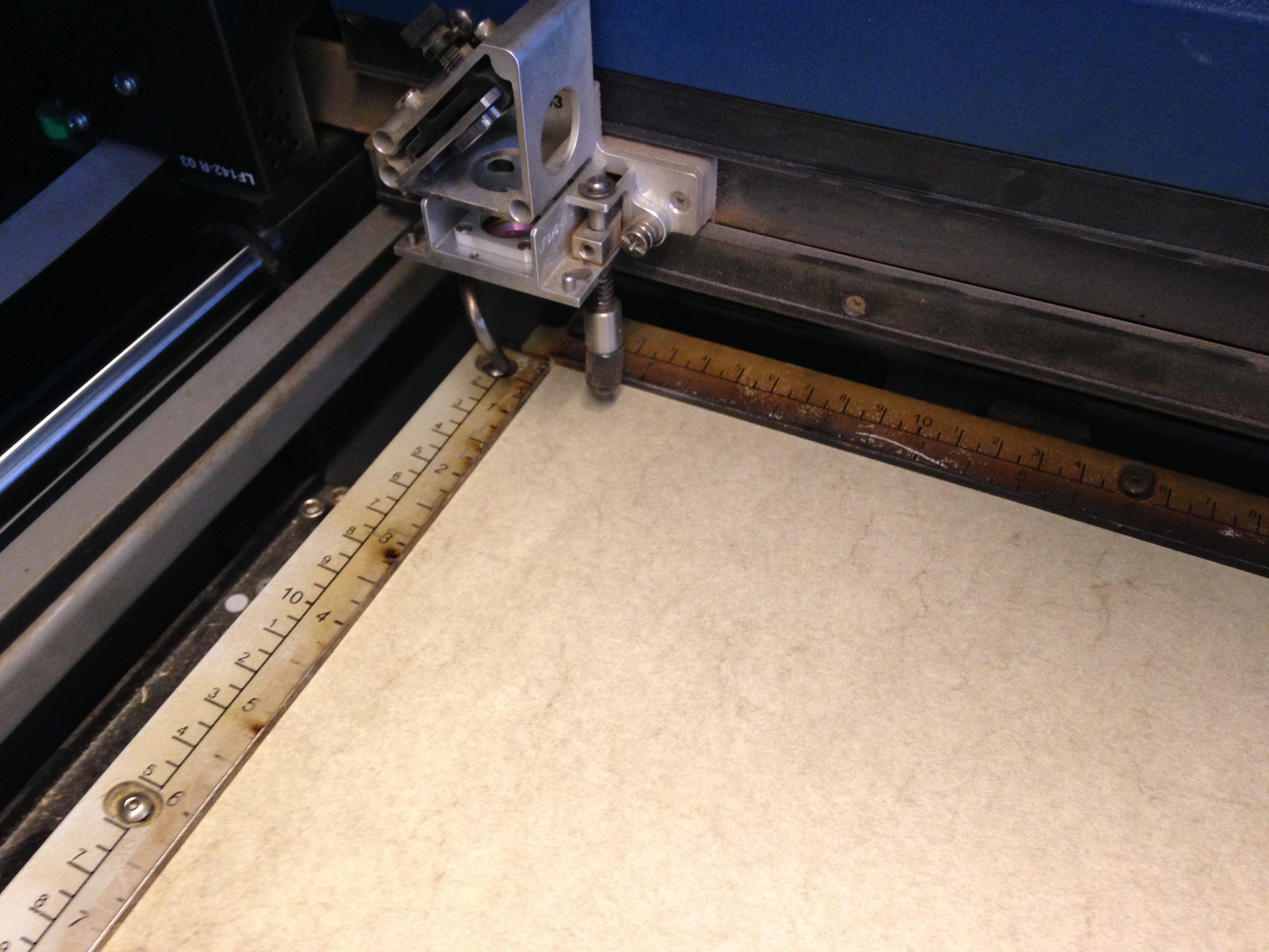
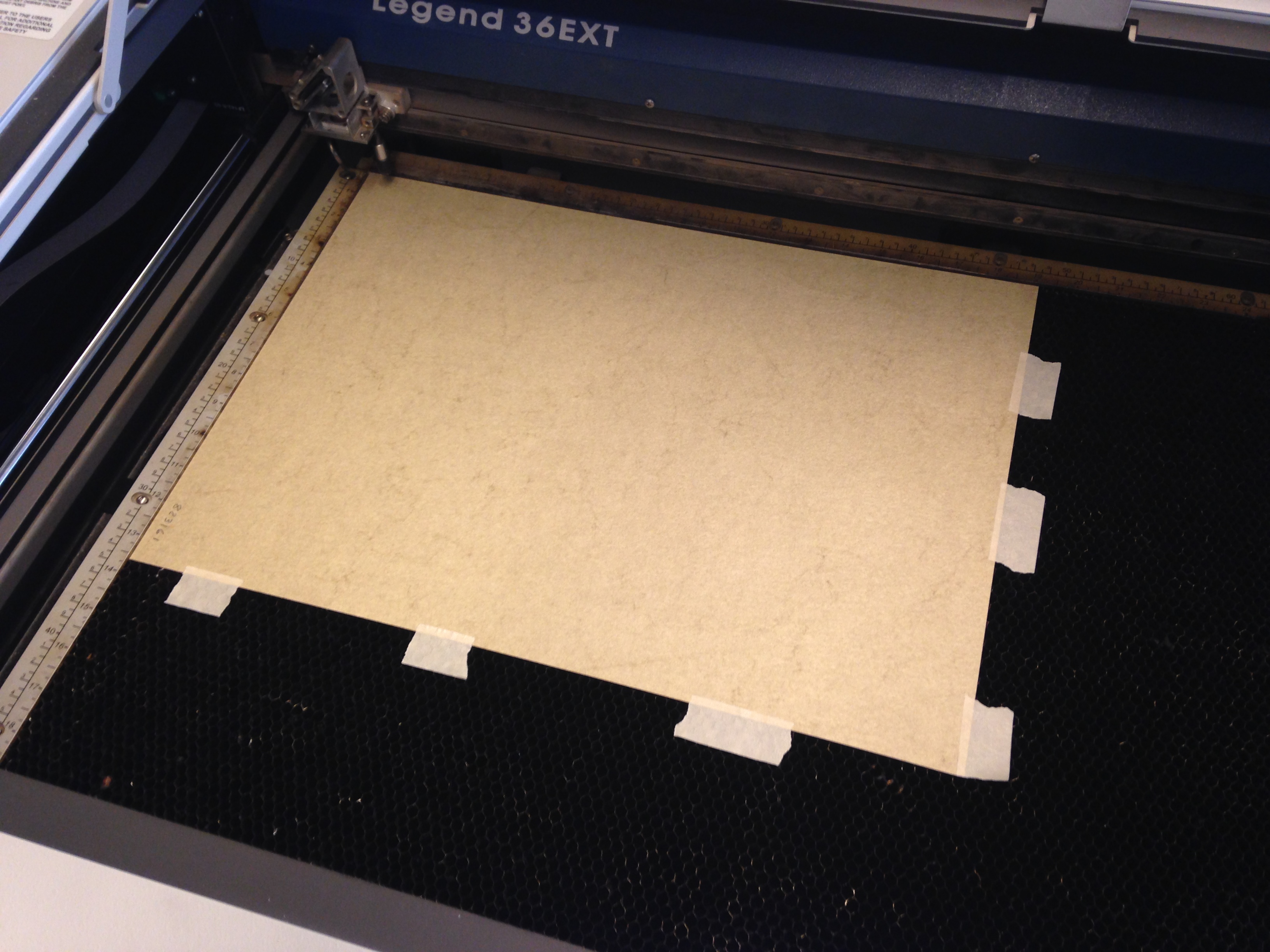
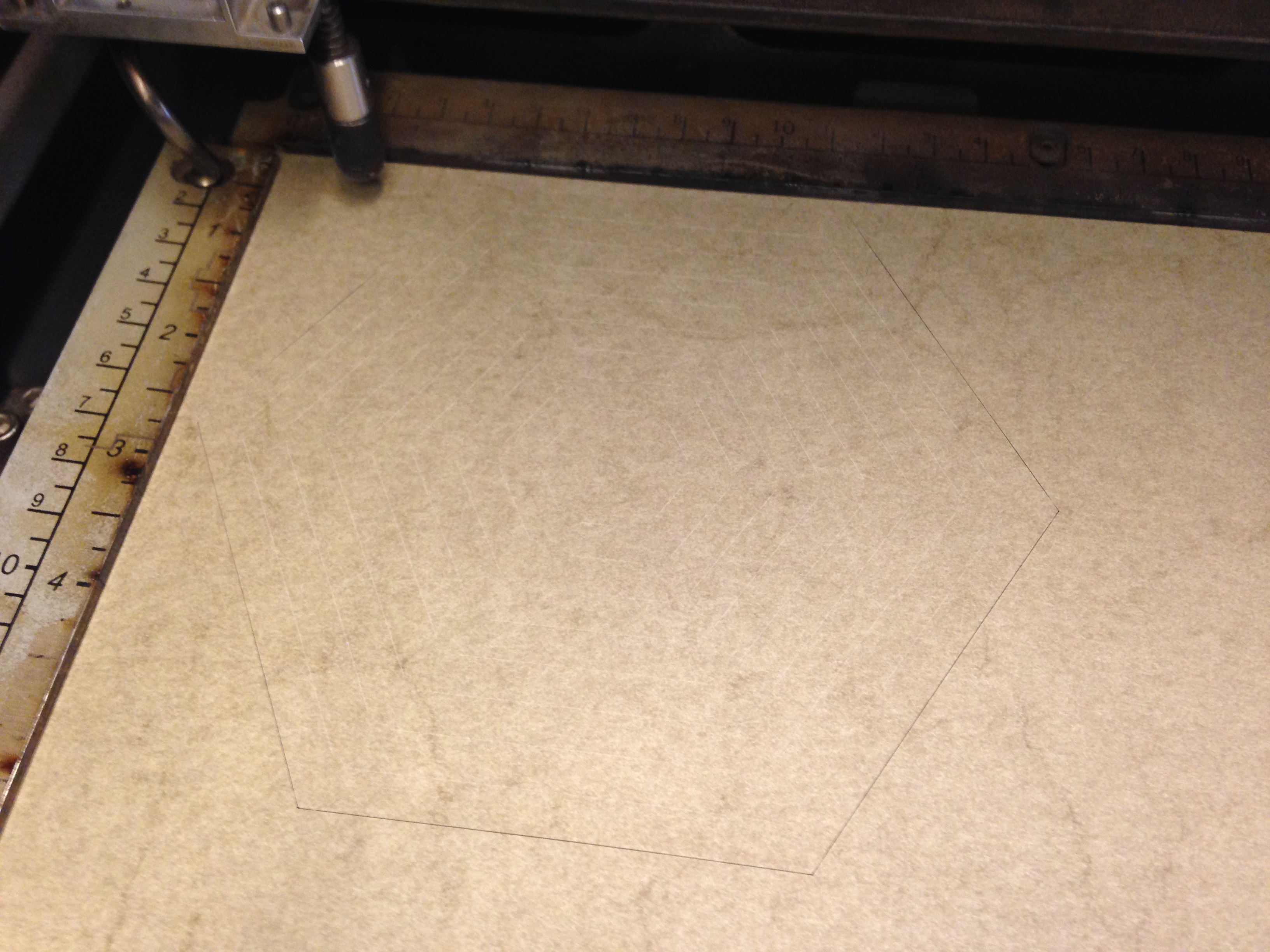
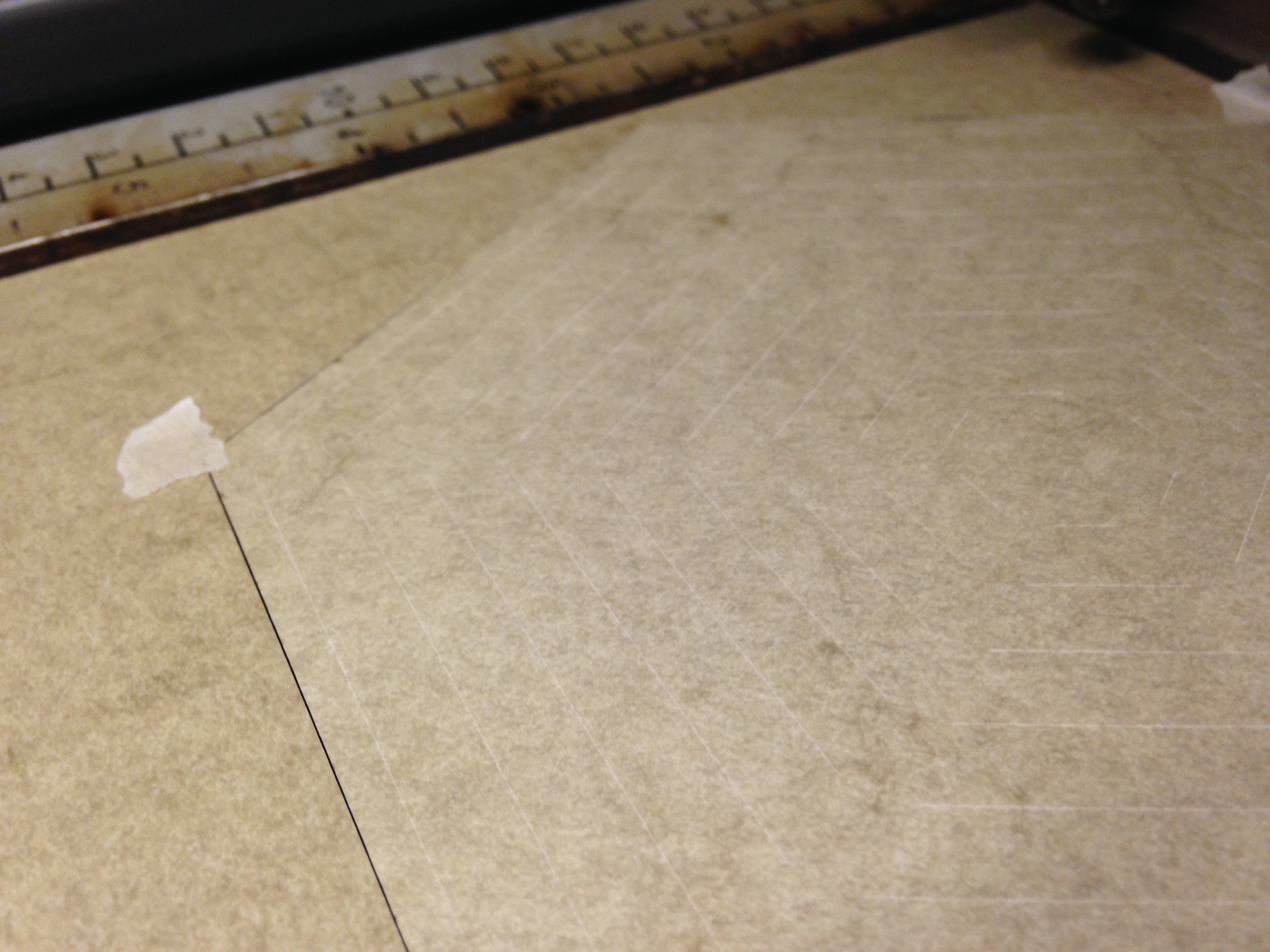
- Epilogs have spring-loaded, hinged guides running along the edge of the honeycomb. Pull these back and set your paper onto the honeycomb, butting the edge up against the edge of the guide and then flip the guide down to clamp the edges of the paper. If you aren't using an Epilog, use masking tape to secure the edges of the paper to the edge of the honeycomb.
- Next tape the remaining edges of the paper down to the honeycomb. There's not a lot of surface area for the tape to grab onto, but it's just enough to hold the paper down.
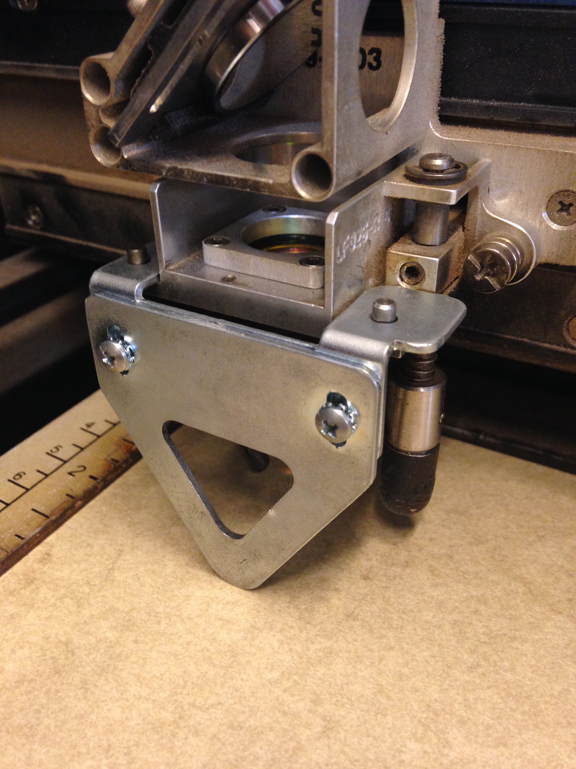
- Focus the laser to the surface of the paper.
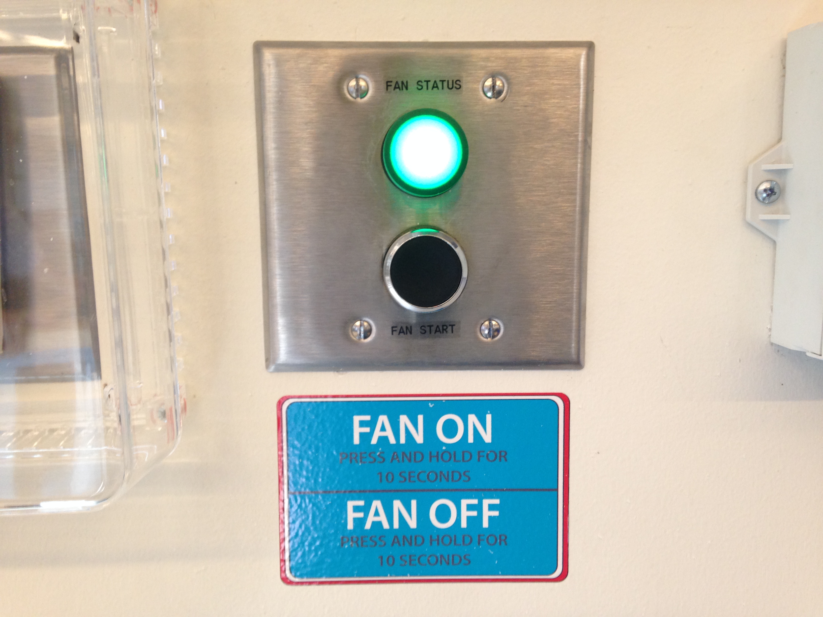
- Make sure your exhaust is turned on-- with down-drafted laser cutters, the exhaust really helps secure the paper to the honeycomb.
Etch
.JPG)
.JPG)
.JPG)
.JPG)
.JPG)
.JPG)
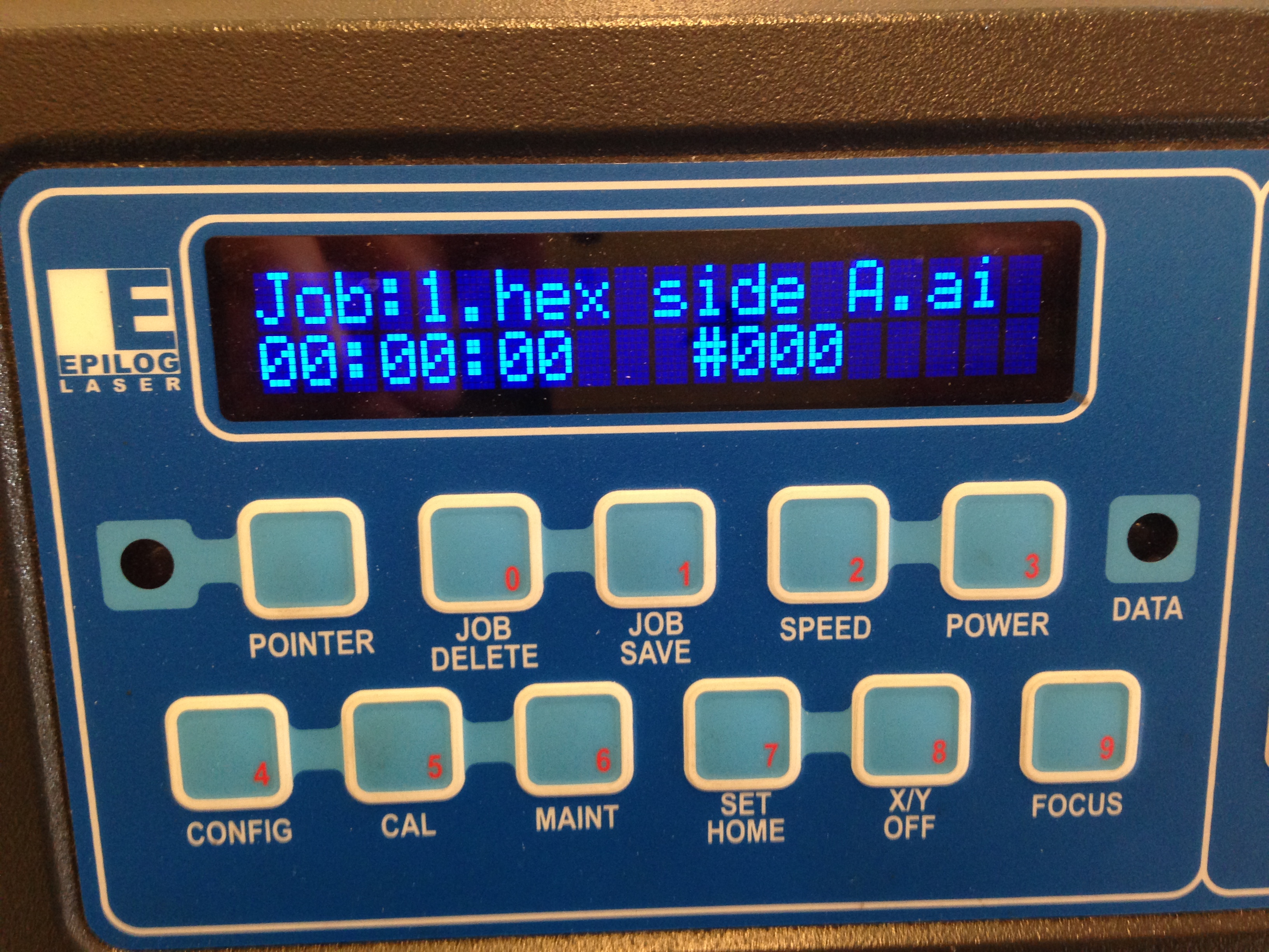
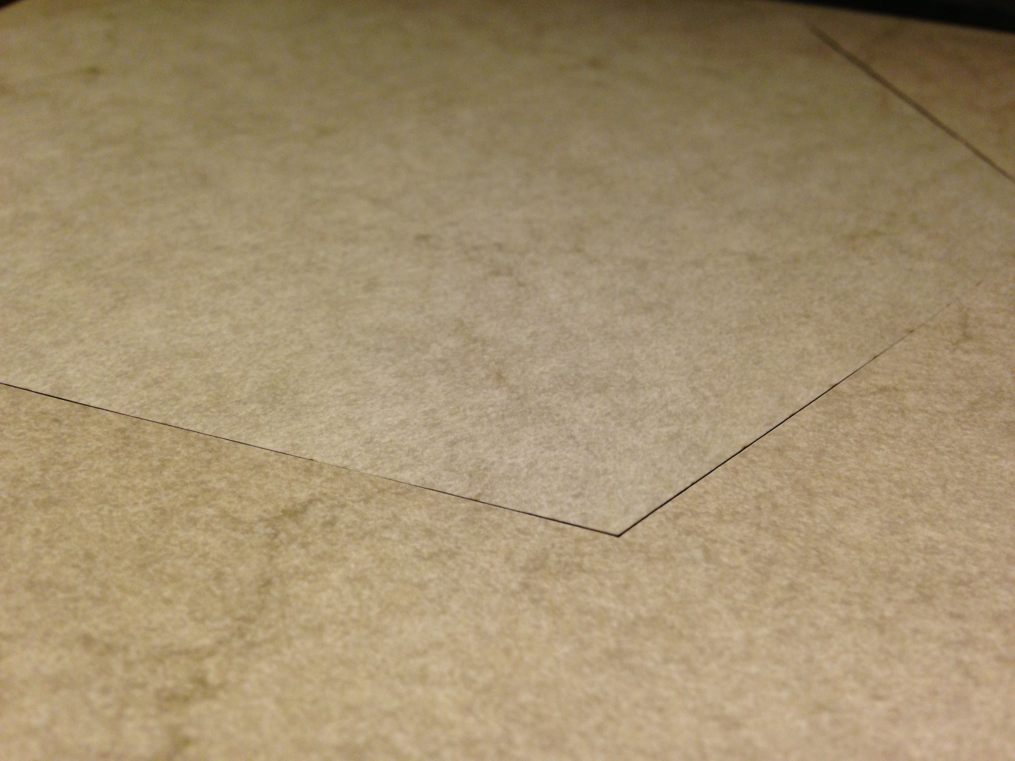
- Run the side A file.
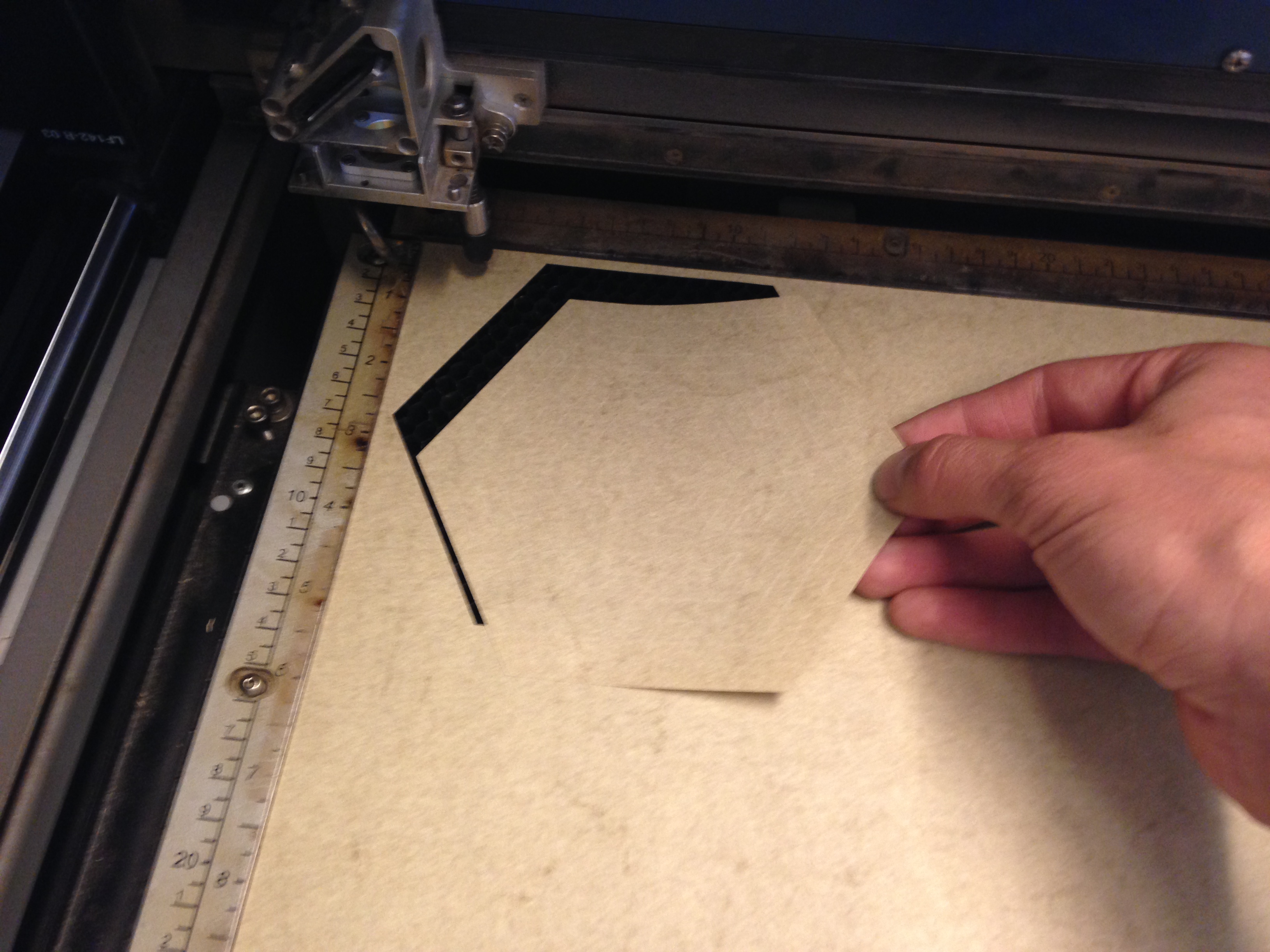
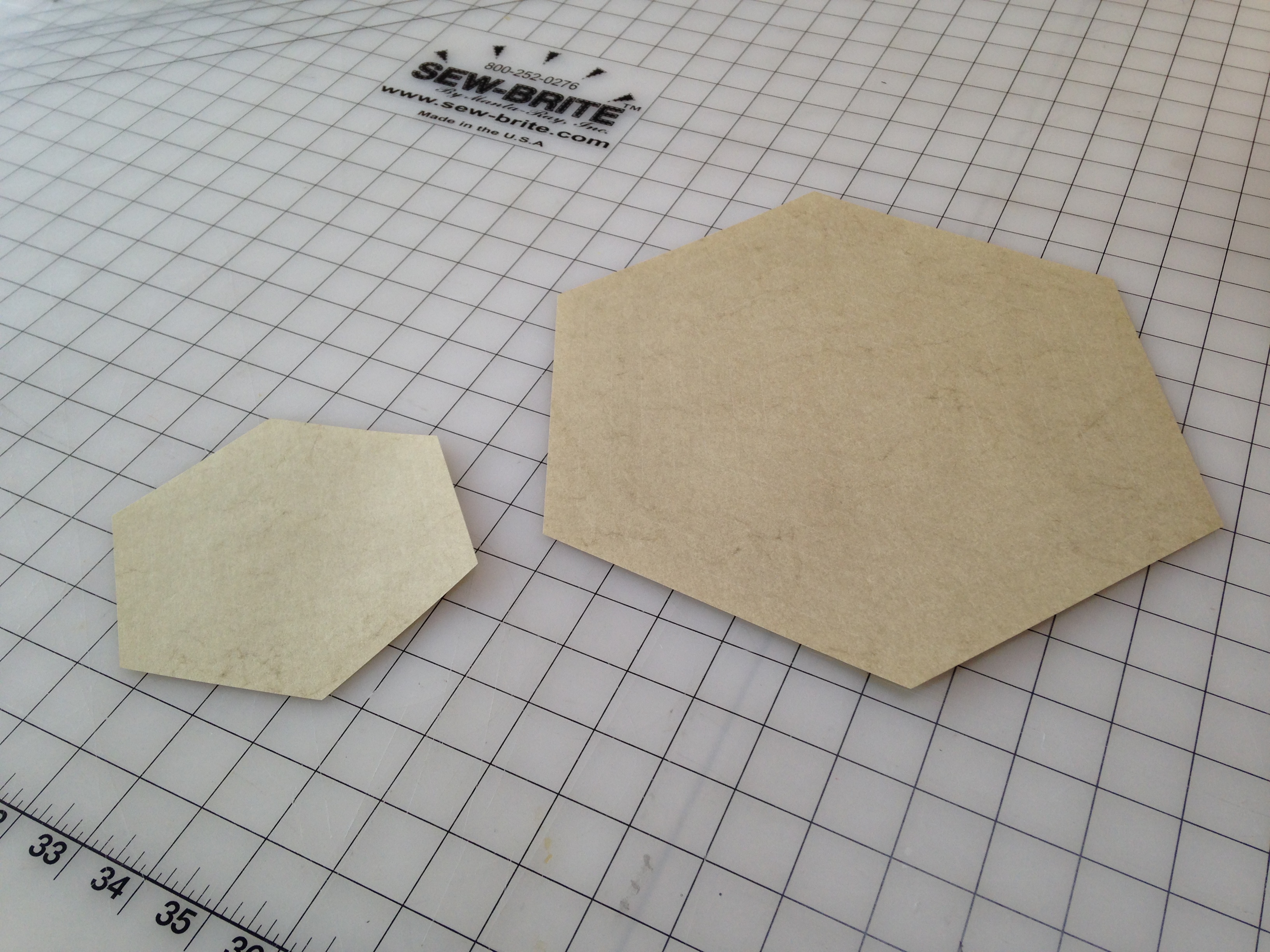
- Carefully remove and flip the etched and cut piece. Depending on the degree of backlash in the laser cutter gantry, you may need to rotate it to fit it precisely into the remaining paper. Small pieces of tape can be used to secure the etched paper for side B etching.
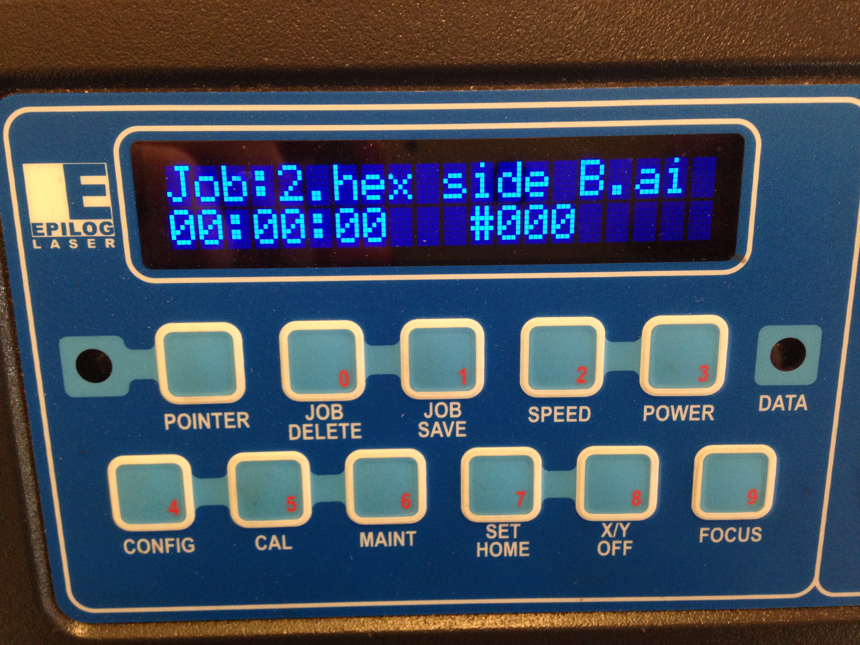
- Run the side B file.
Fold
.JPG)
.JPG)
.JPG)
.JPG)
.JPG)
.JPG)
.JPG)
.JPG)
.JPG)
.JPG)
.JPG)
.JPG)
.JPG)
.JPG)
.JPG)
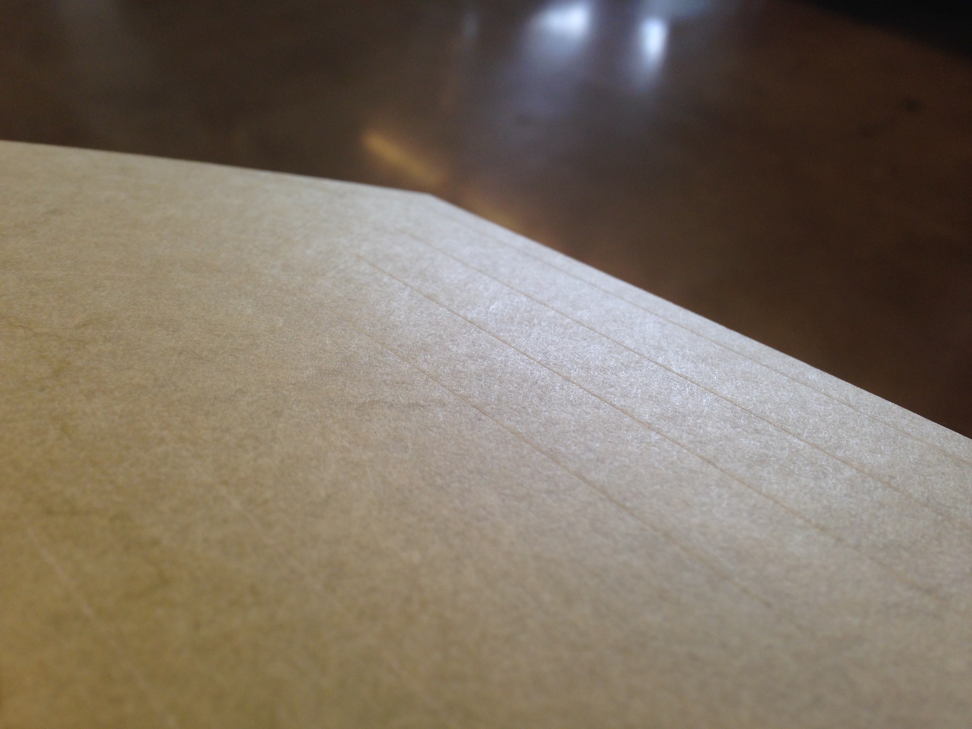
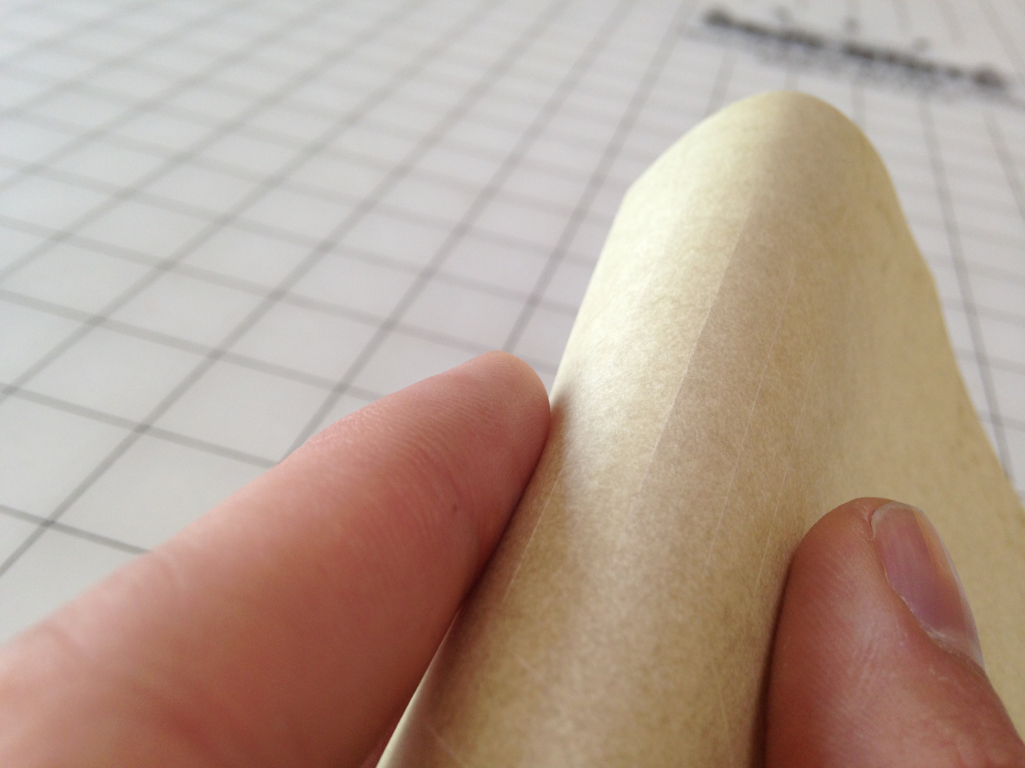
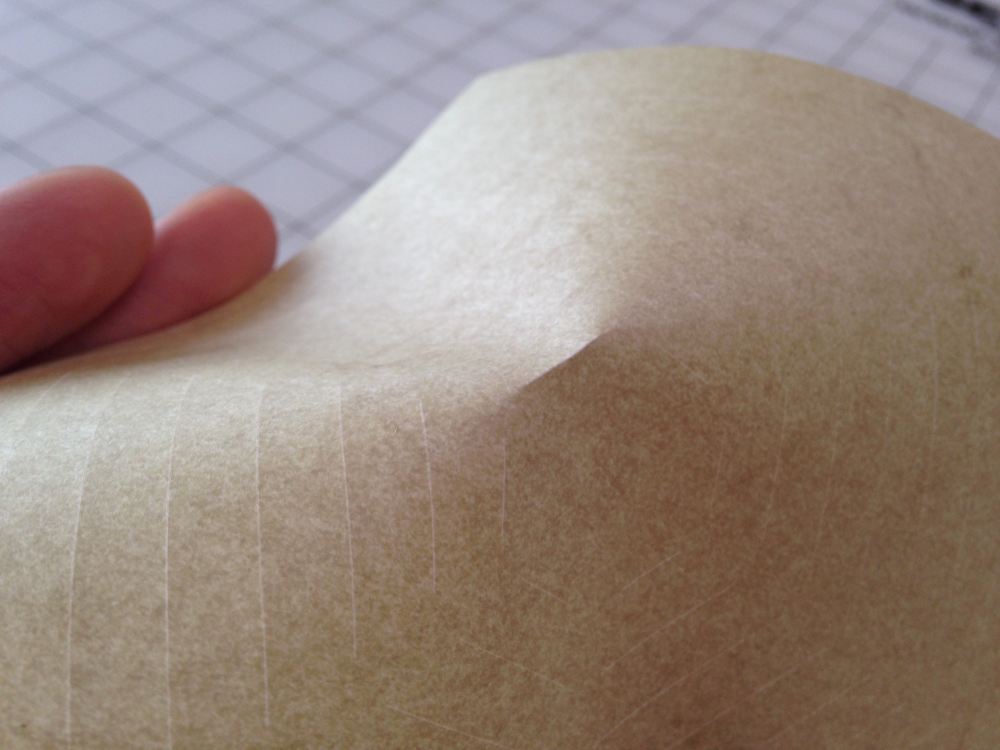
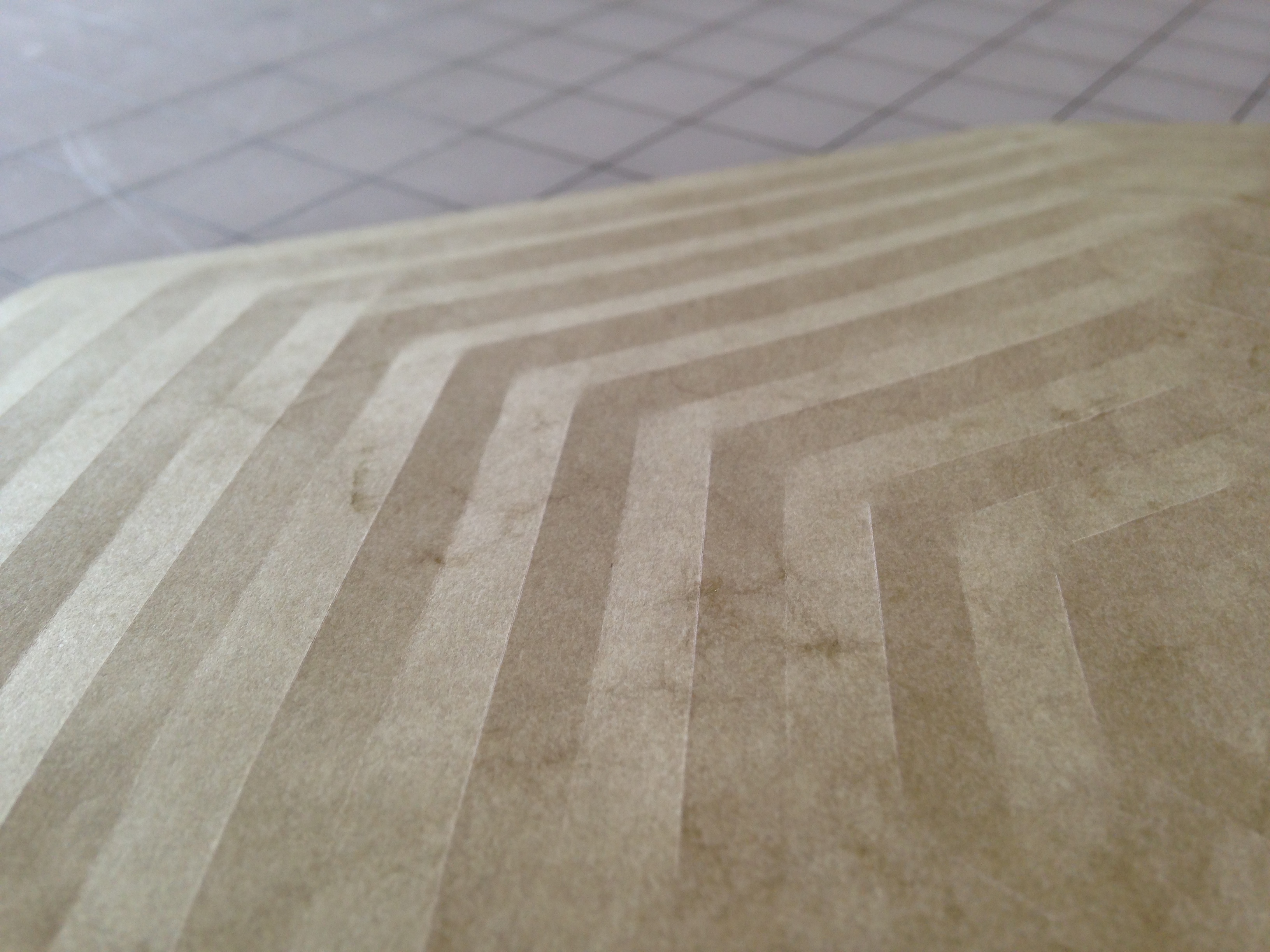
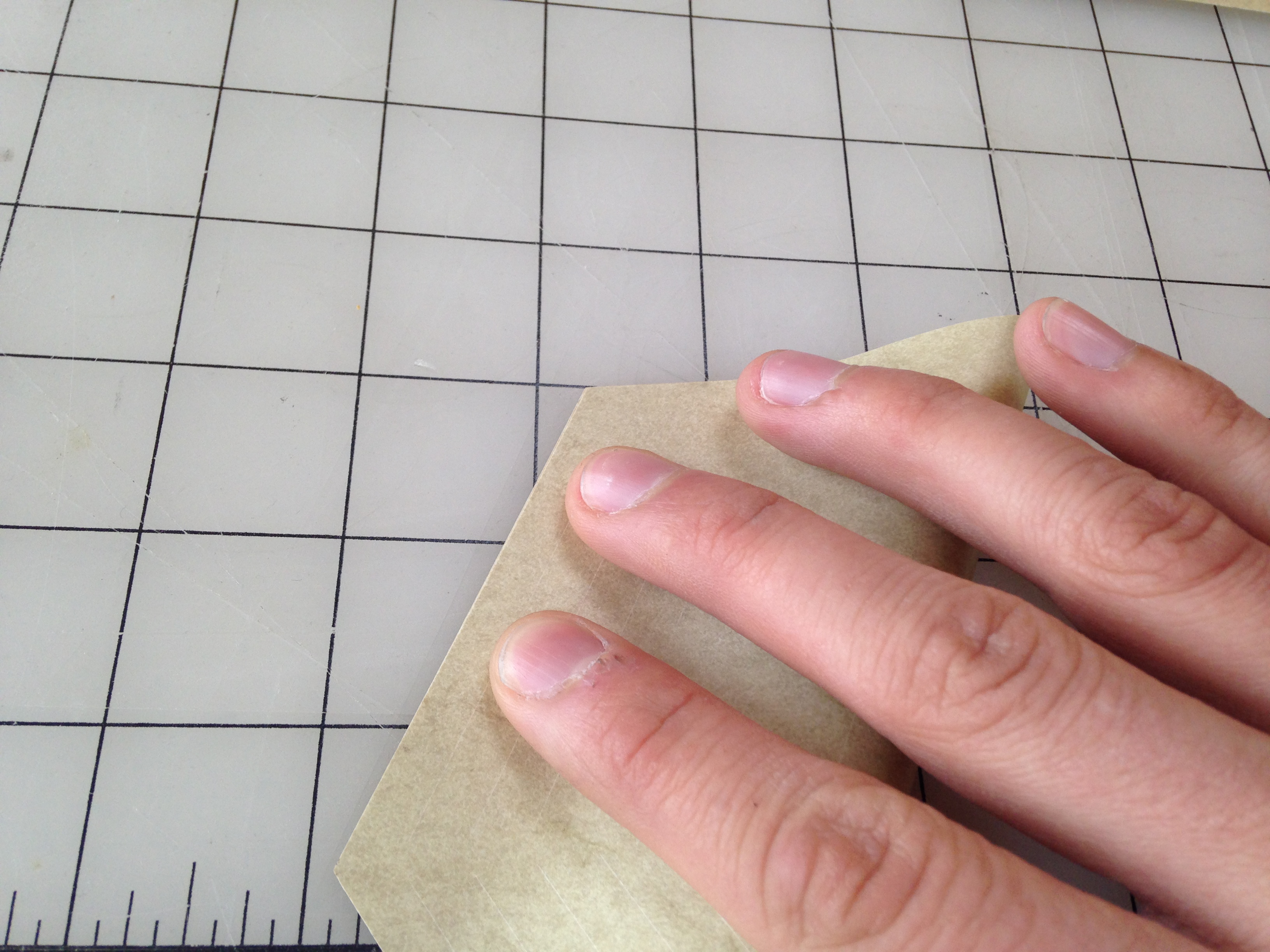
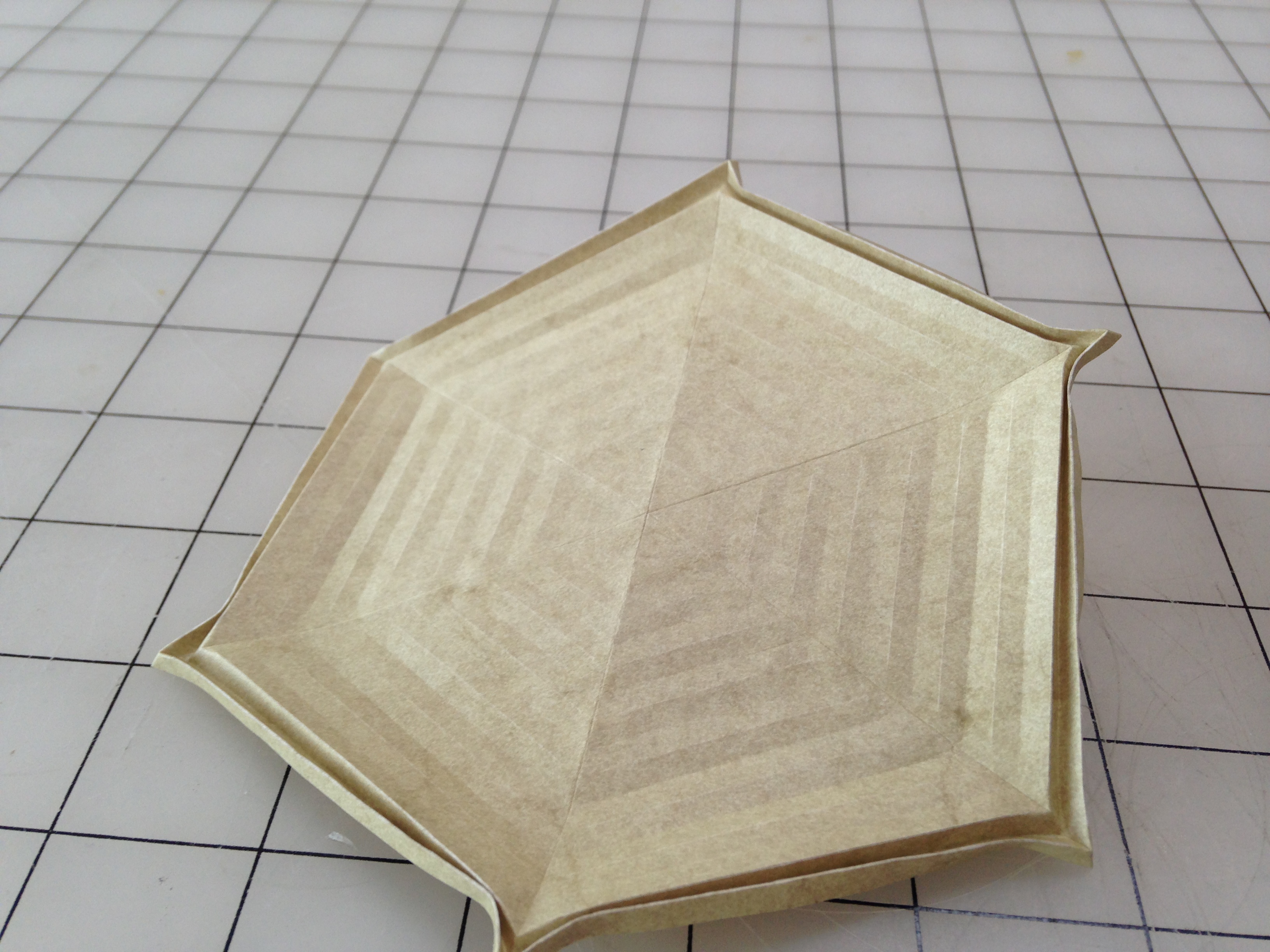
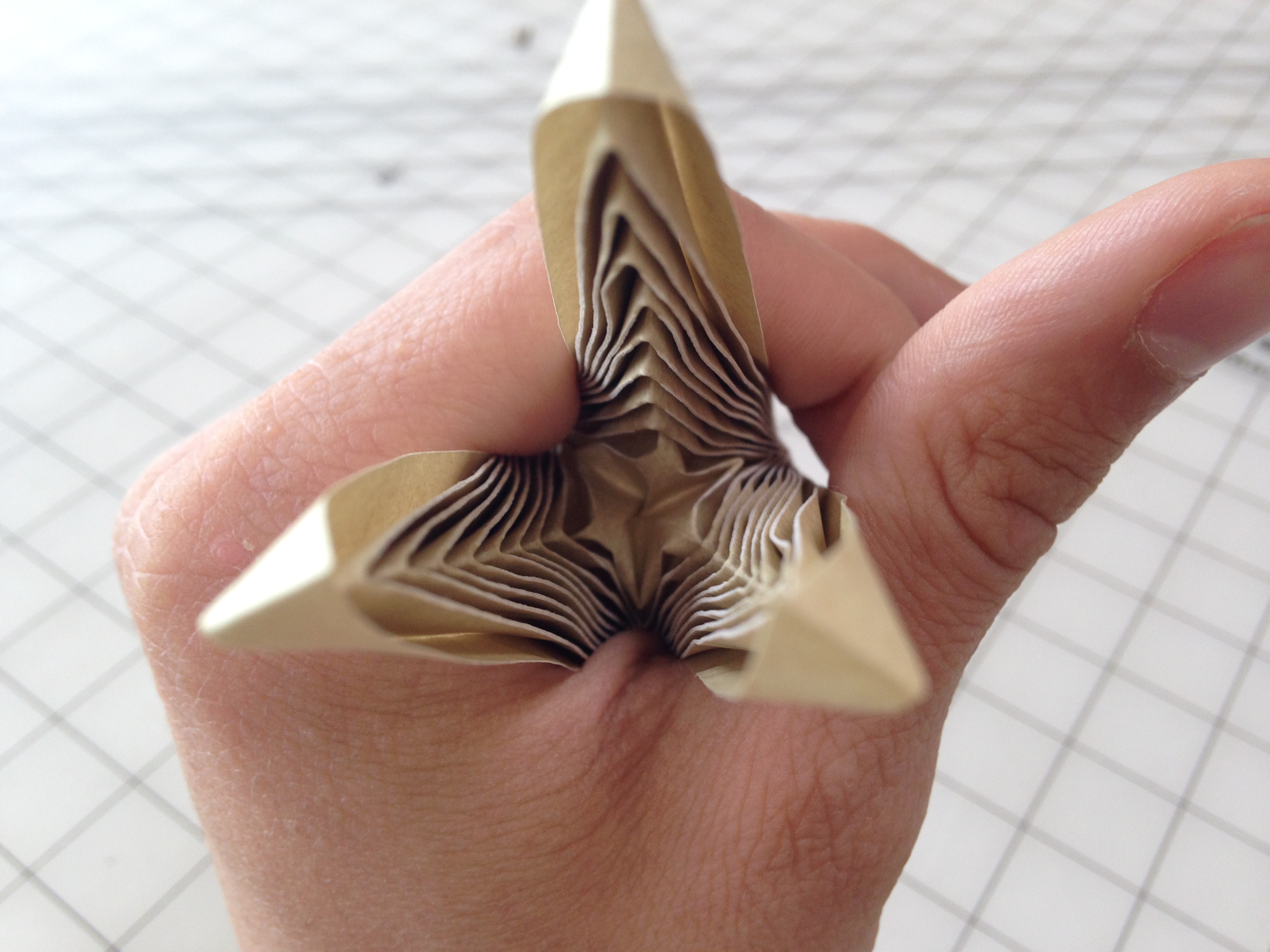
Start by folding along all the crease paths on each side of the piece, taking care not to "follow-through" across the entire piece: stop folding where the etched line stops. Once you have folded all the laser-etched creases, fold the piece in half three times to connect each vertex in the hexagon (in this case) with a manually-formed fold. Fold each one of these three folds back on itself to make it bi-directional. These folds are best not etched because they see a lot more tension than the rest of the folds in the form.
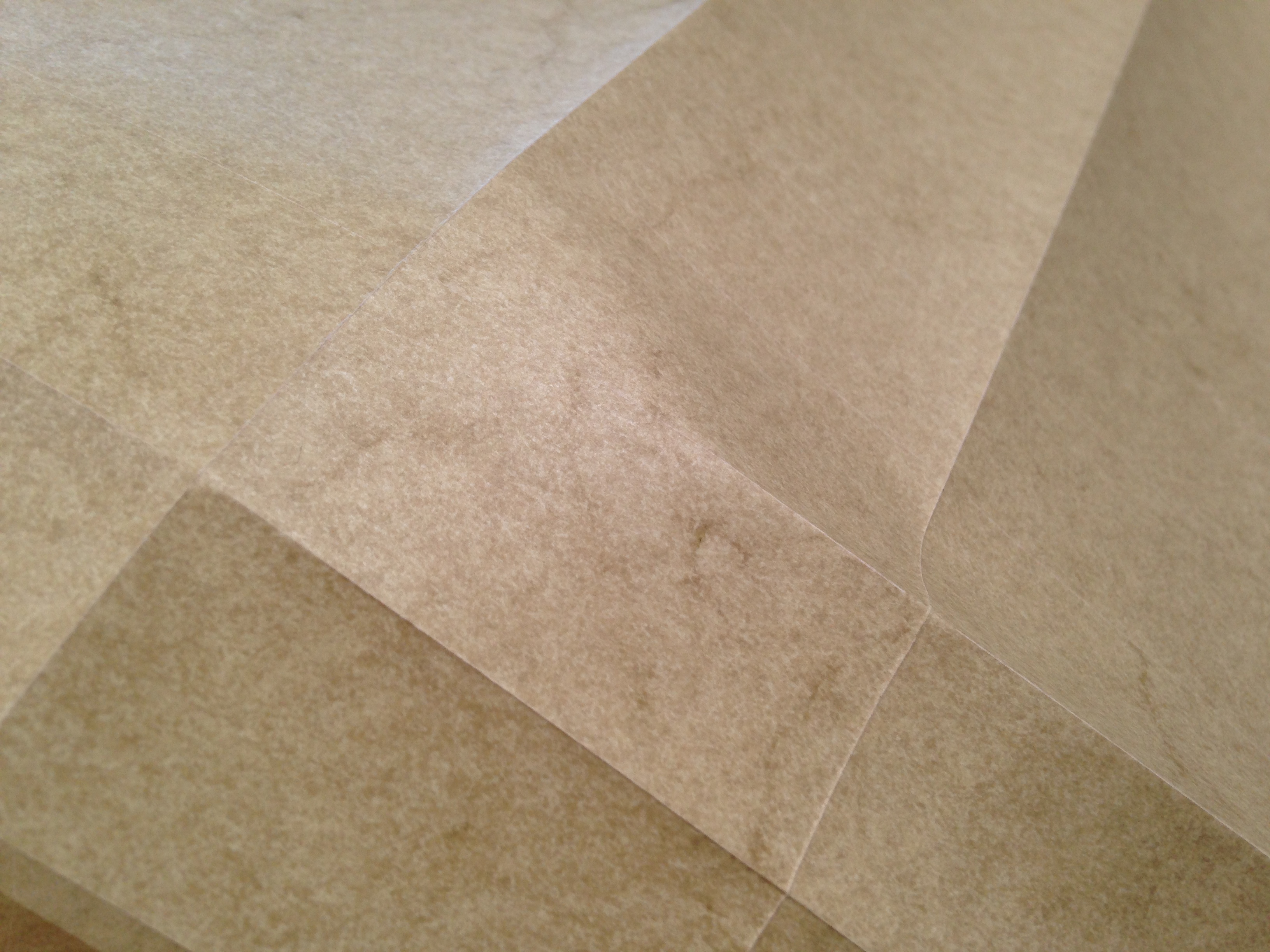
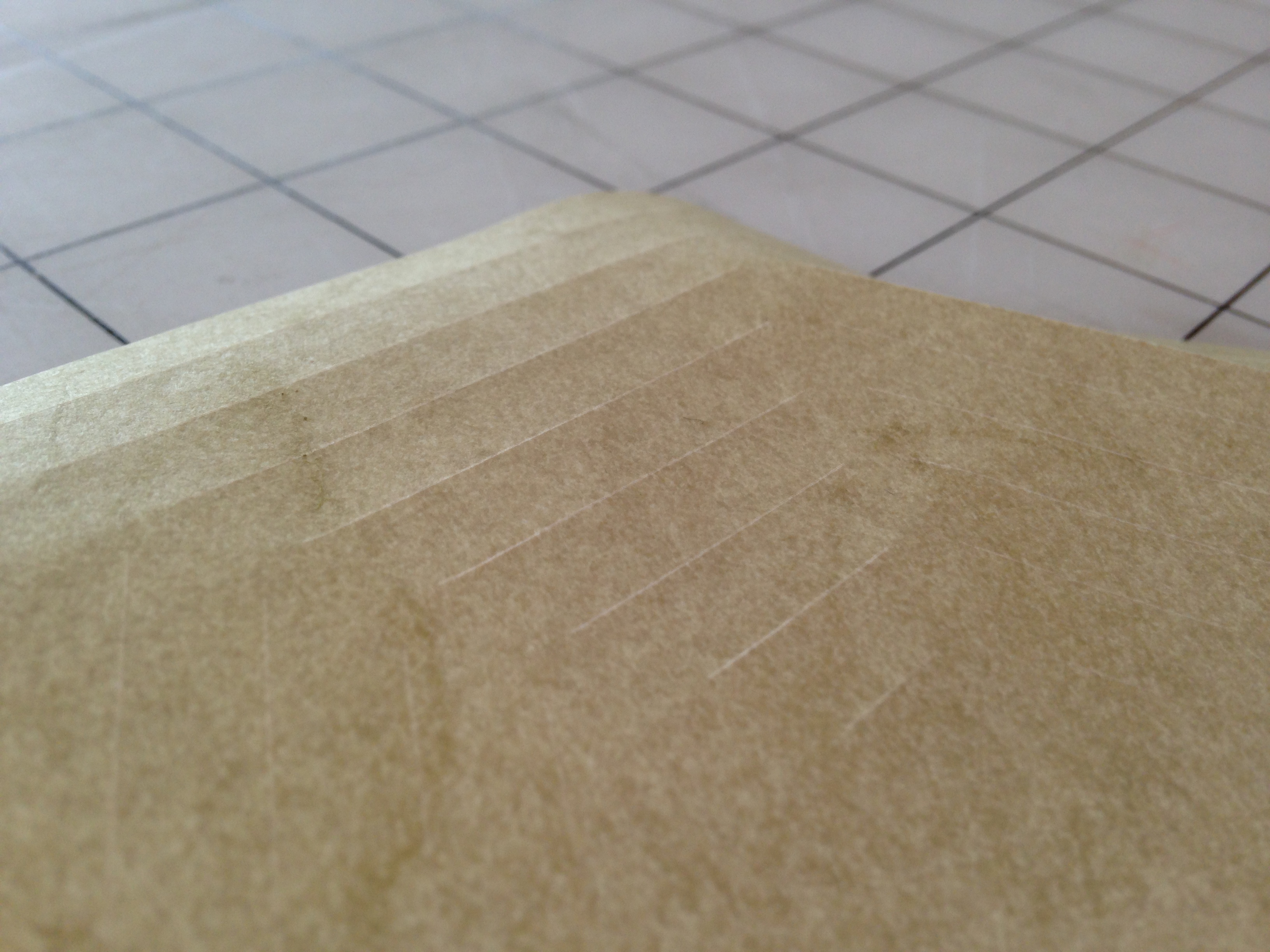
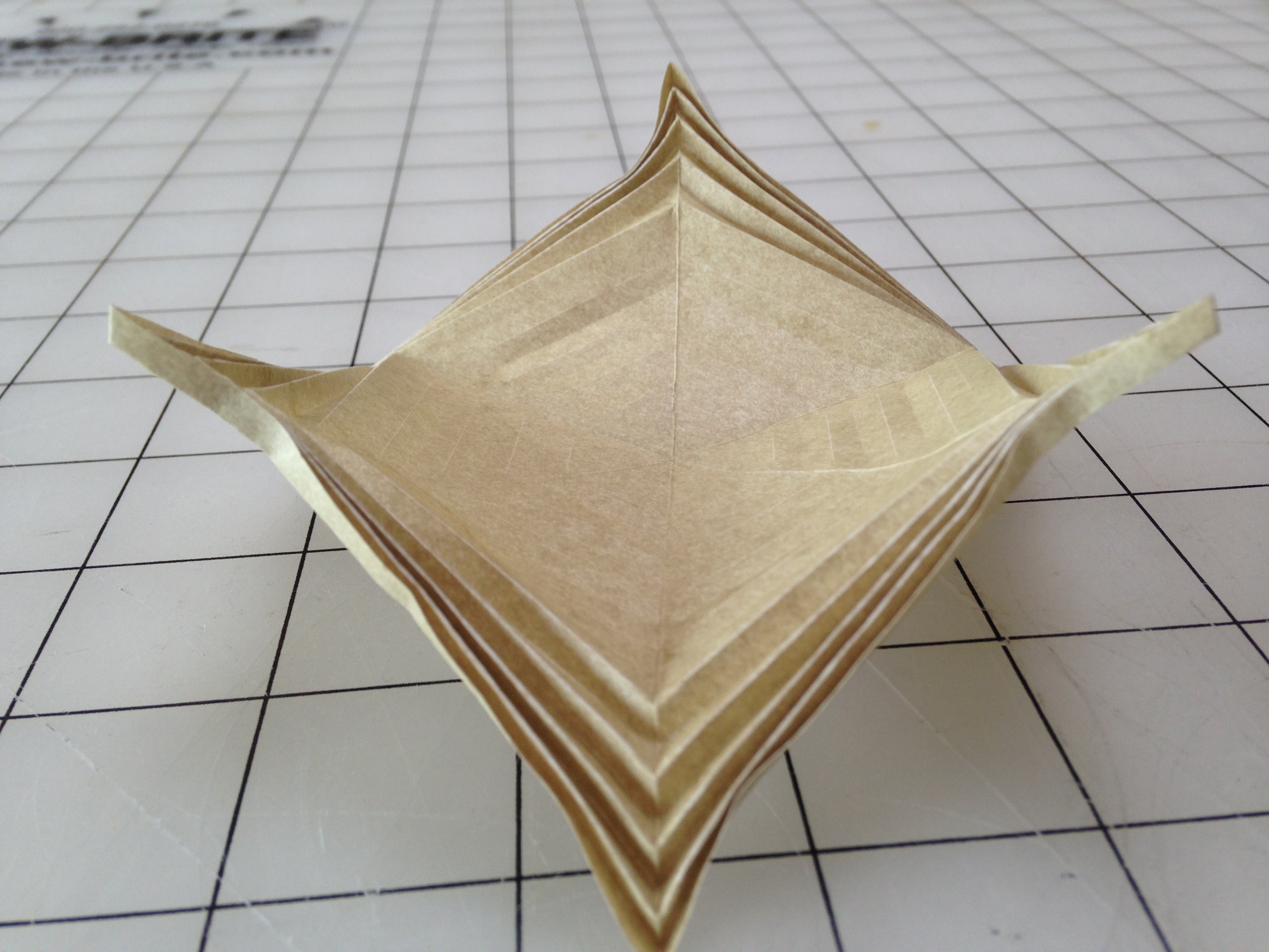
After pre-folding all the etched creases and applying the radial folds, work you way from the outside in, bunching the folds together and taking care to properly form the intersections of the manual radial folds and etched folds. Because the laser is operating at it's lowest emitting power setting to create the etches, the laser stops emitting as the gantry decelerates when it leads into and out of corners, which means that the etch paths stop "early". The center-most folds may require the tip of a knife or a skewer to enforce the proper topology.
Experiment
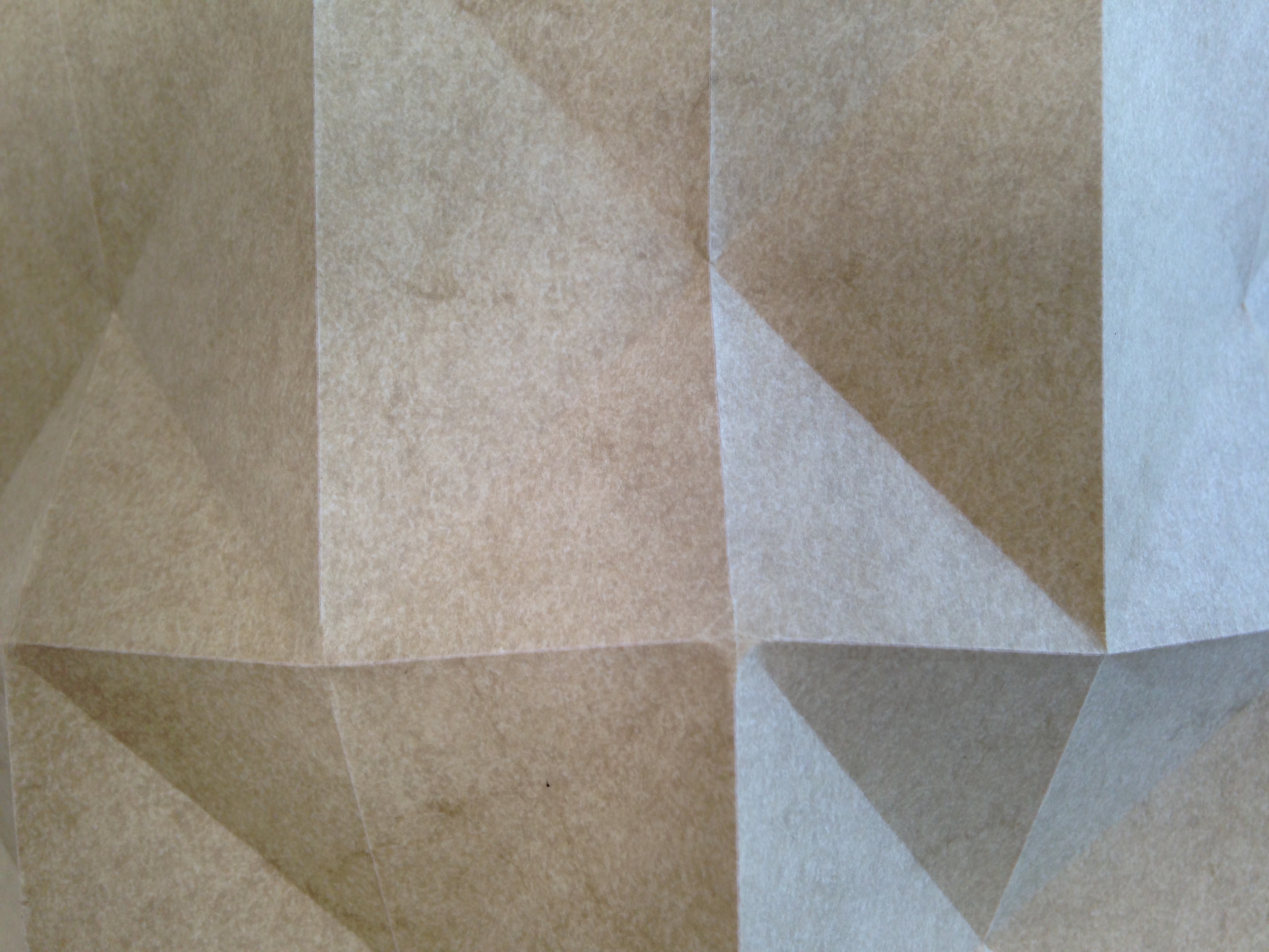
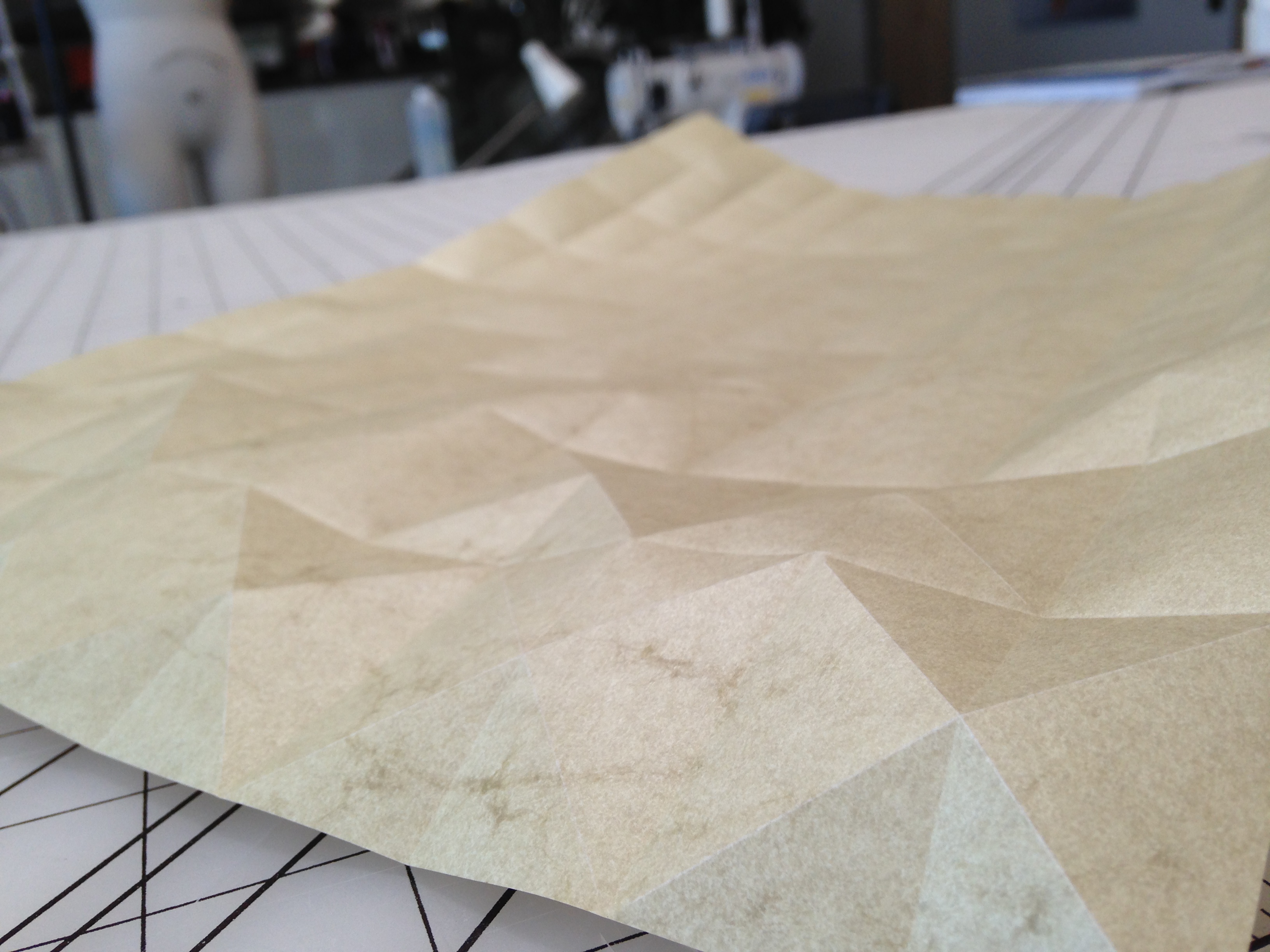.JPG)
.JPG)
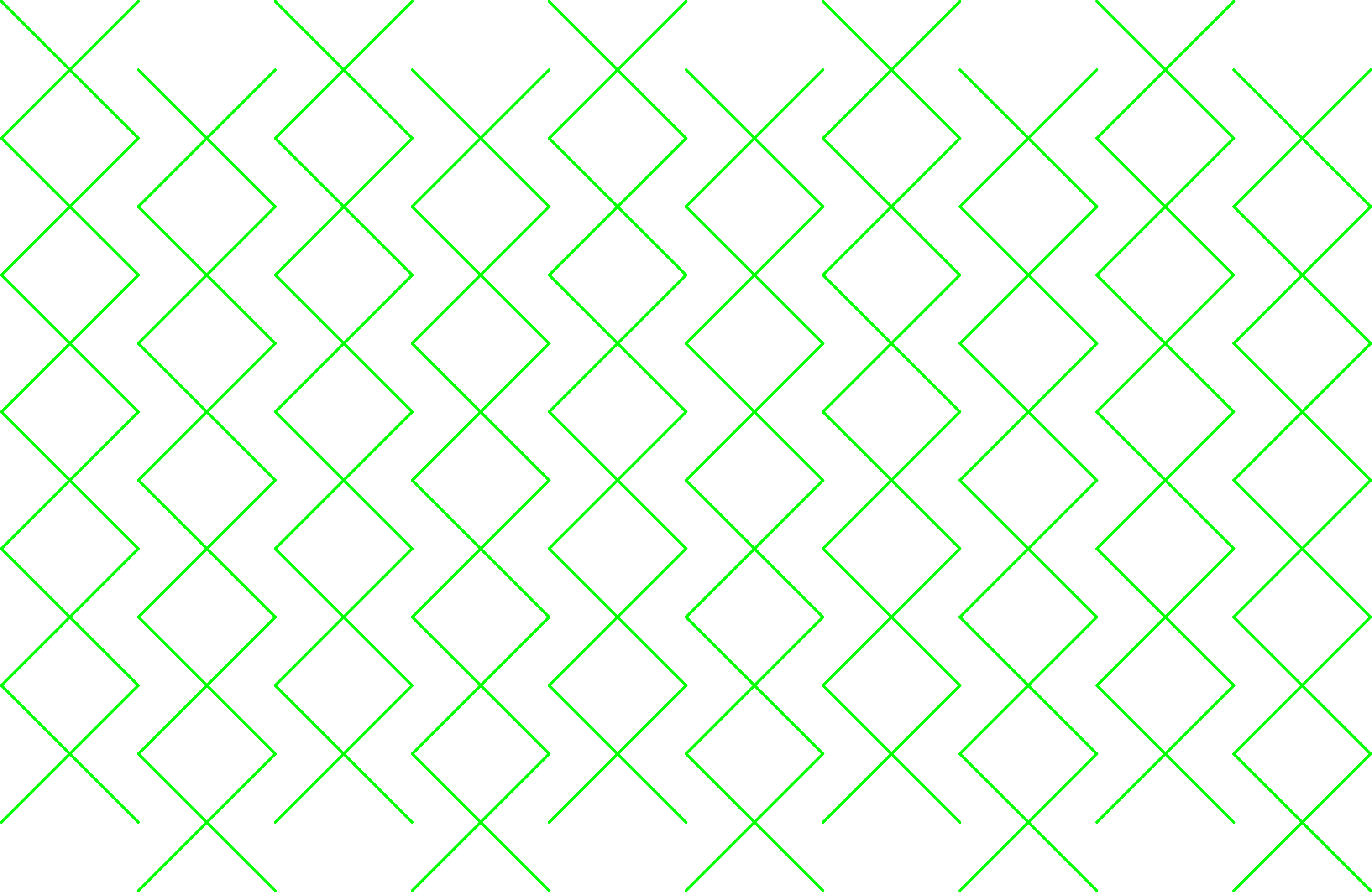


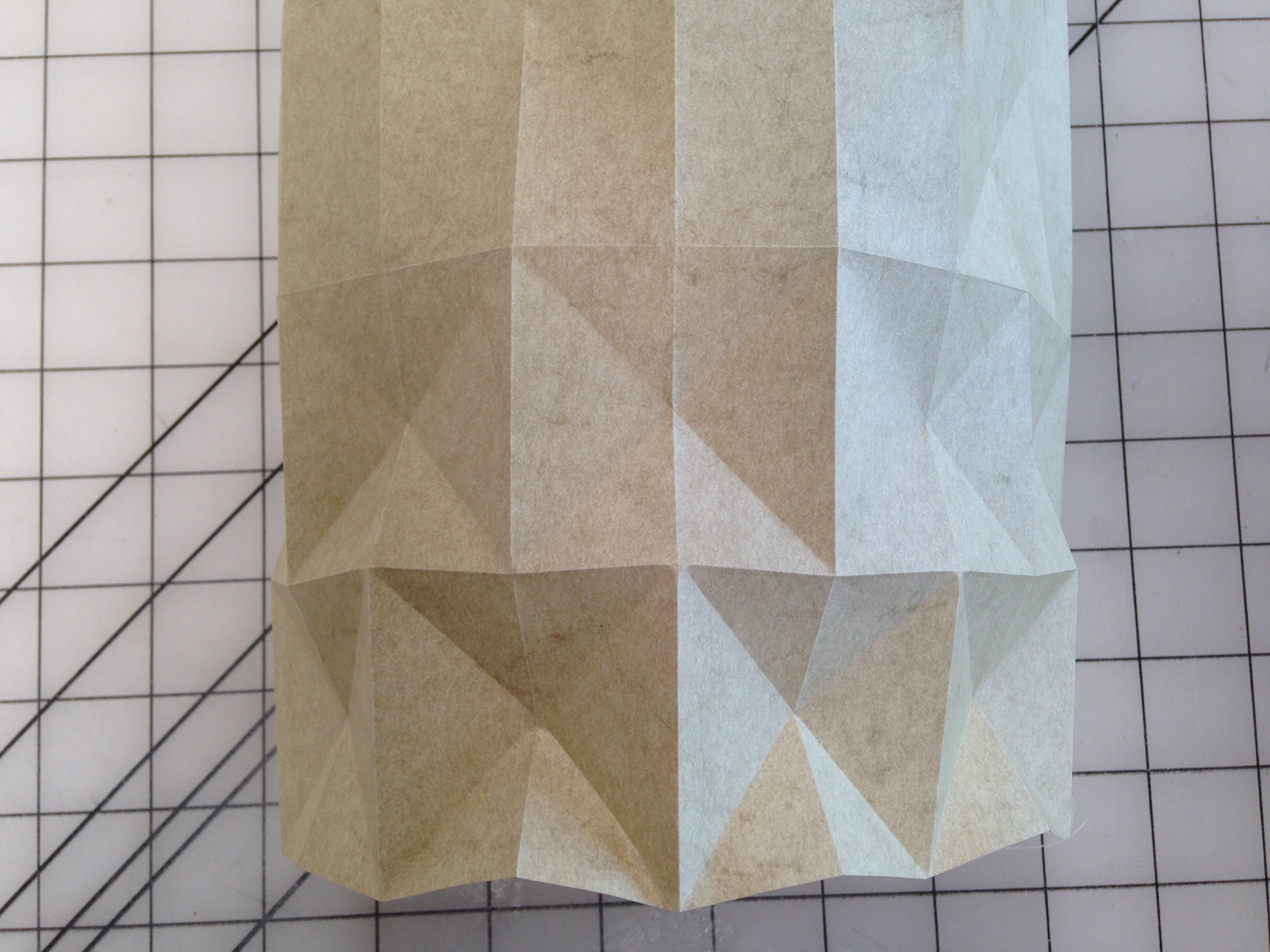
This is a very general strategy for encoding 3D form information into a 2D stock material. Please experiment with different geometries and materials!