Laser Cut Press-fit of a Baobab Tree
by JoseNarbona in Design > Art
496 Views, 6 Favorites, 0 Comments
Laser Cut Press-fit of a Baobab Tree
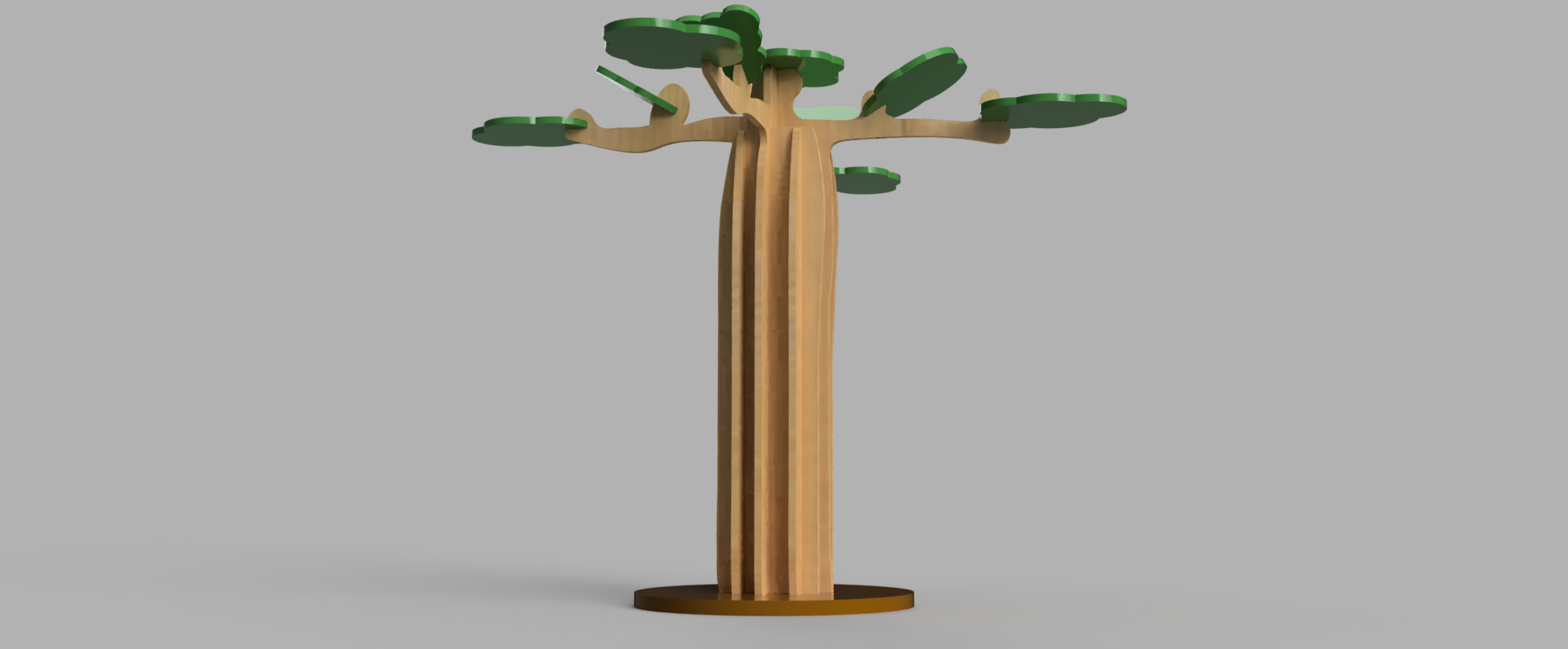
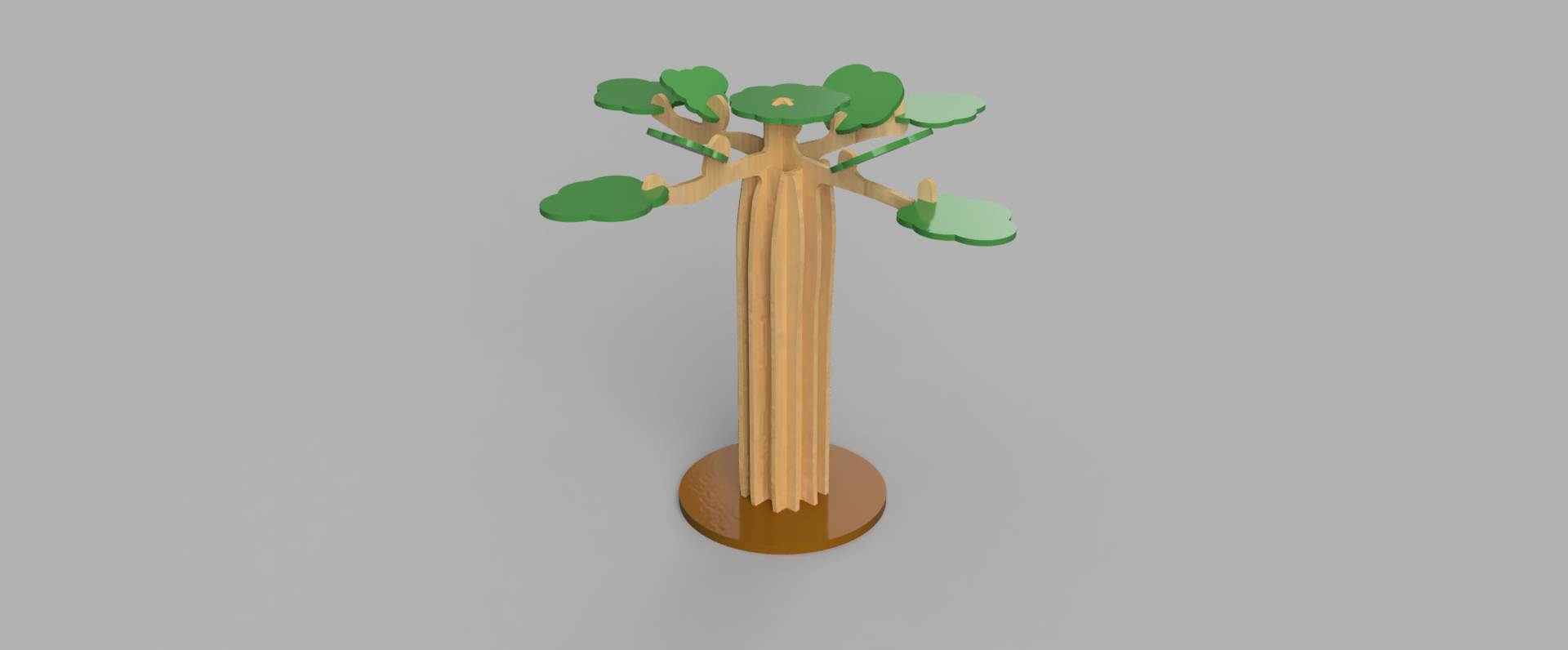
This is a tutorial for a laser cut press-fit of a Baobab tree.
Materials:
- Plywood 3.175 mm thick (1/8 inch) for the trunk and leaves.
- Plywood 6.350 mm thick (1/4 inch) for the base.
- Green paint for the leaves. Color HTML code number 609650.
- Brown paint for the base. Color HTML code number 906225.
- Varnish for the parts that make up the trunk and branches.
Tools:
- Trotec Speedy 300 laser cutter.
- Equipment for spraying parts such as a Wagner Wagner Control Pro 130 Power Tank Airless Stand Paint Sprayer.
Software:
- Fusion 360.
- Inkscape.
- FreeCad.
NOTE:
This tutorial does not count for the laser kelf. I recommend following
this other tutorial for kelf correction: https://www.instructables.com/Kerf-Correction-for-...
Design the Trunk Sketch With Fusion 360
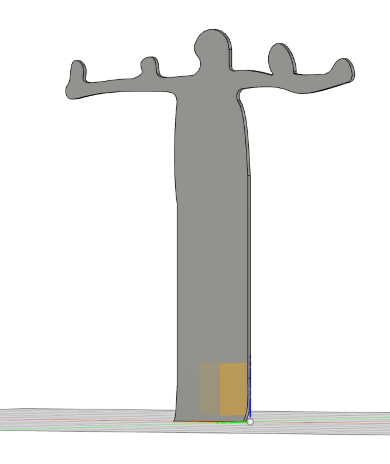
Sketch one of the tree trunks. I have used the spline drawing tool extensible thought all my sketches. This has caused opening the DXF with Inkscape. I will explain later how to overcome this situation.
Prefix measure parameters for the plywood thickness as t for 1/8 inch and 2t for 1/4 inch. Go to modify and then to change parameters.
Extrude this first sketch of the trunk and start sketching the leaves.
Coping and Pasting New the Trunk.
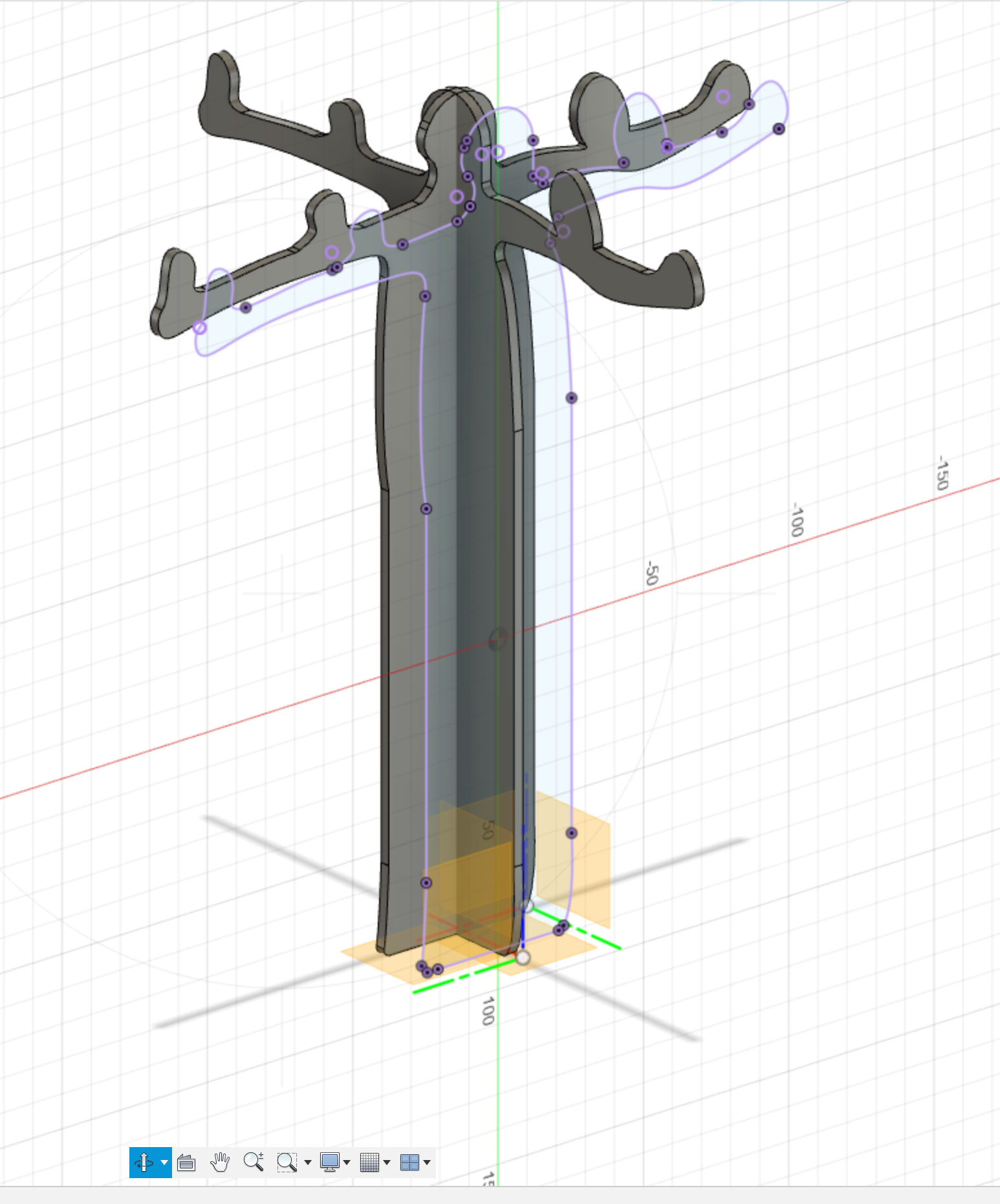
Copy the whole trunk component and paste it new. Not just paste but paste new. This will make each component independent of each other.
Otherwise, changes in one will affect the copy. Move the second trunk so it is perpendicular to the first.
Sketching of the Leaves
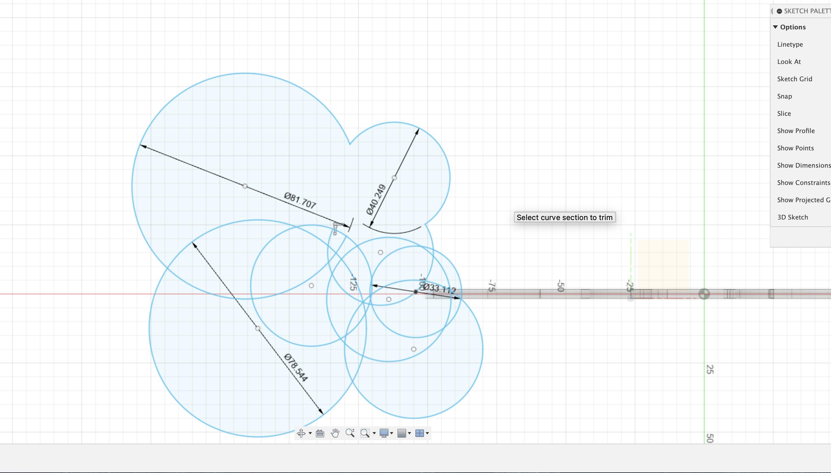
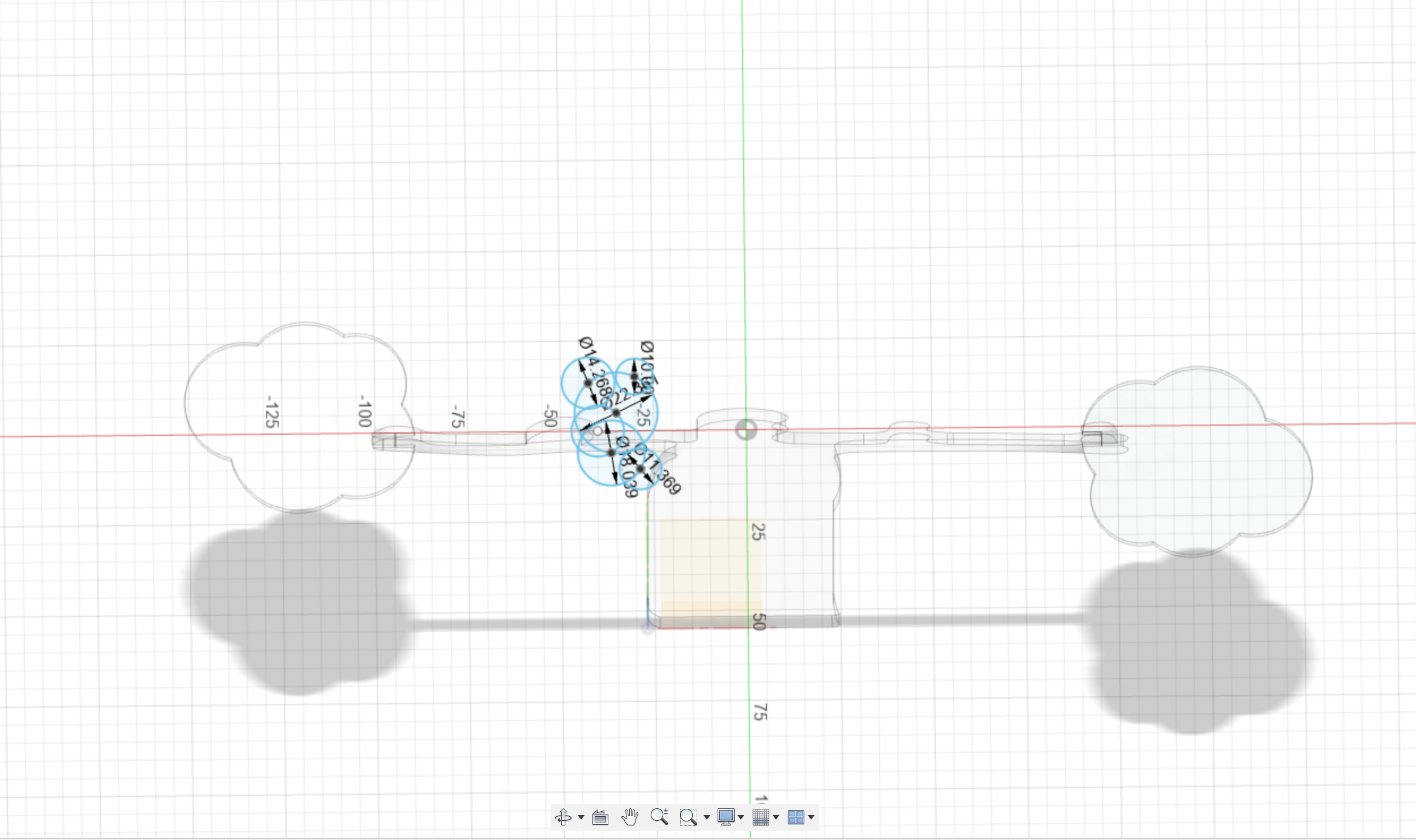
Create a new offset plane where you want the leaves to intersect with the branches. Some off the planes will be at an angle, chose the construct then plane at angle.
Sketch the leaves. I did use only circles and then timing the lines I did not want.
Extrude the leaves sketch.
Creating the Joints Between the Branches and the Leaves.
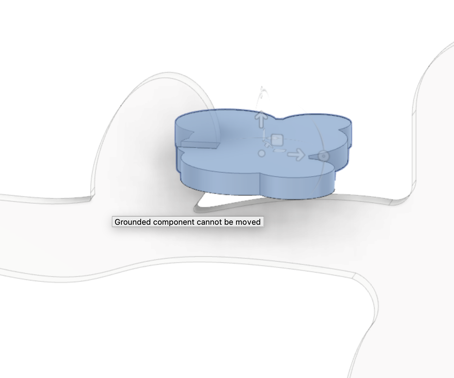
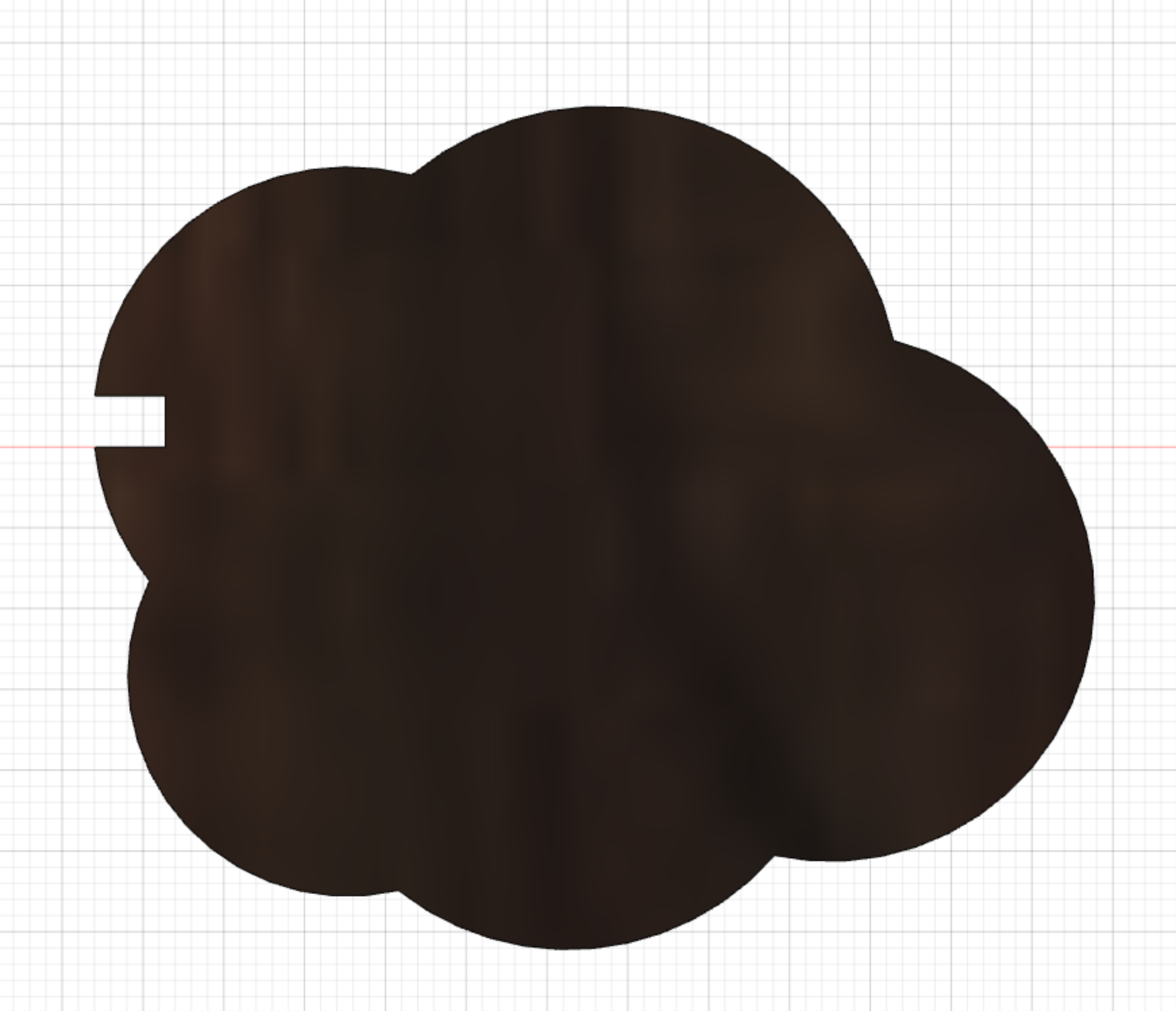
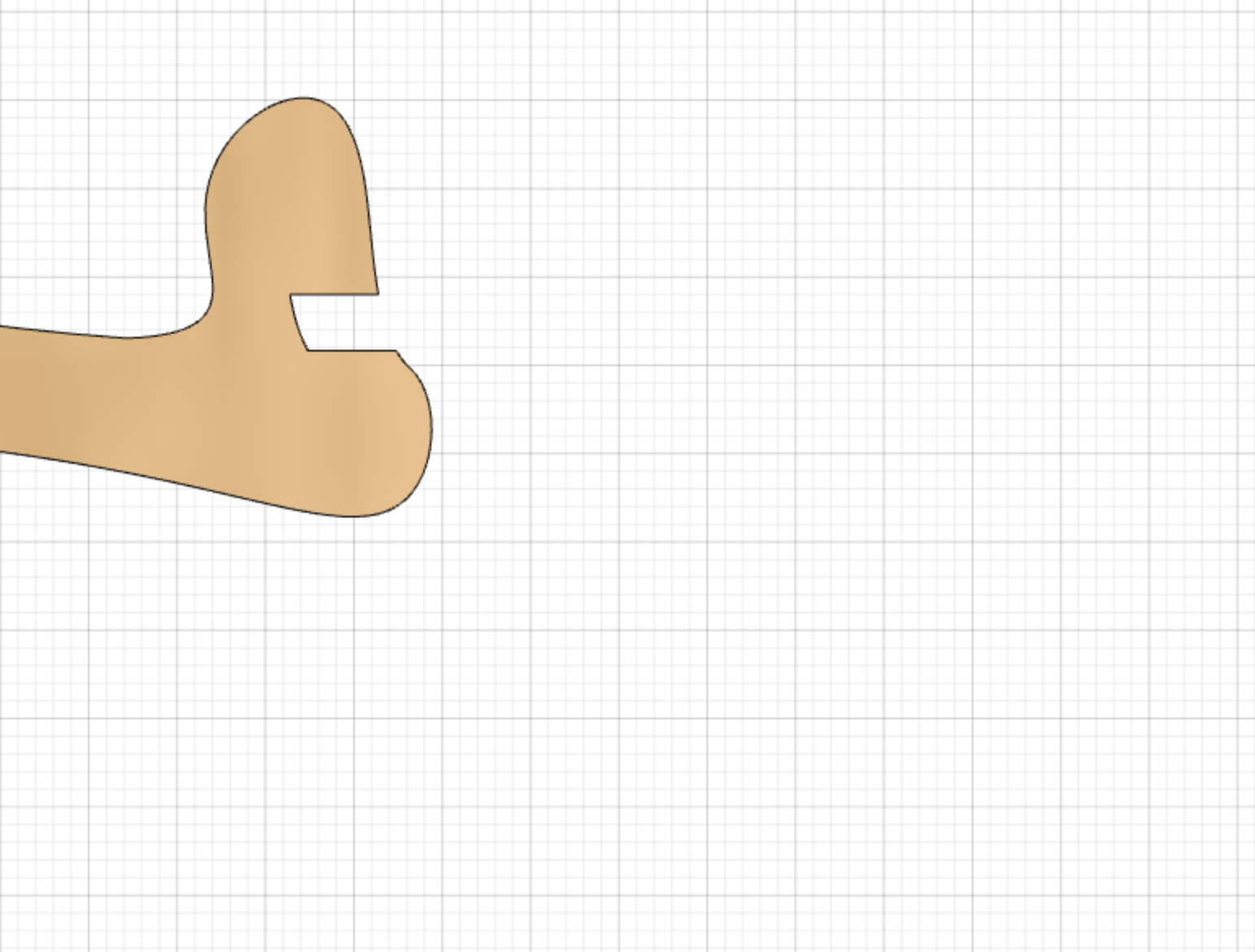
Position the leaves where you want them to go then separate them from the branches halfway of the joint. This way you will be positioning the peaces only halfway into the joint. You will see why in a second.
Now we will be extracting the material from the branch that the leaves are occupaing. Go to combine and selection 1 will be the trunk and 2 the leaves. Select cut and keep tools.
We have extracted the needed part from the branch Now, move the leaves all the way into the intended joint. And remove material from the leave as before but now selection 1 will be the leaves and 3 the trunk. We have finished the joint.
Repeat for each leaves-trunk joint.
More information on how to create this cut in this video: https://www.youtube.com/watch?v=7riGolu7BpA&list=PLvA9hh_QZuJzBxdTy6YVNpn3UW_hceb7a
Building the External 4 Components for the Trunk.
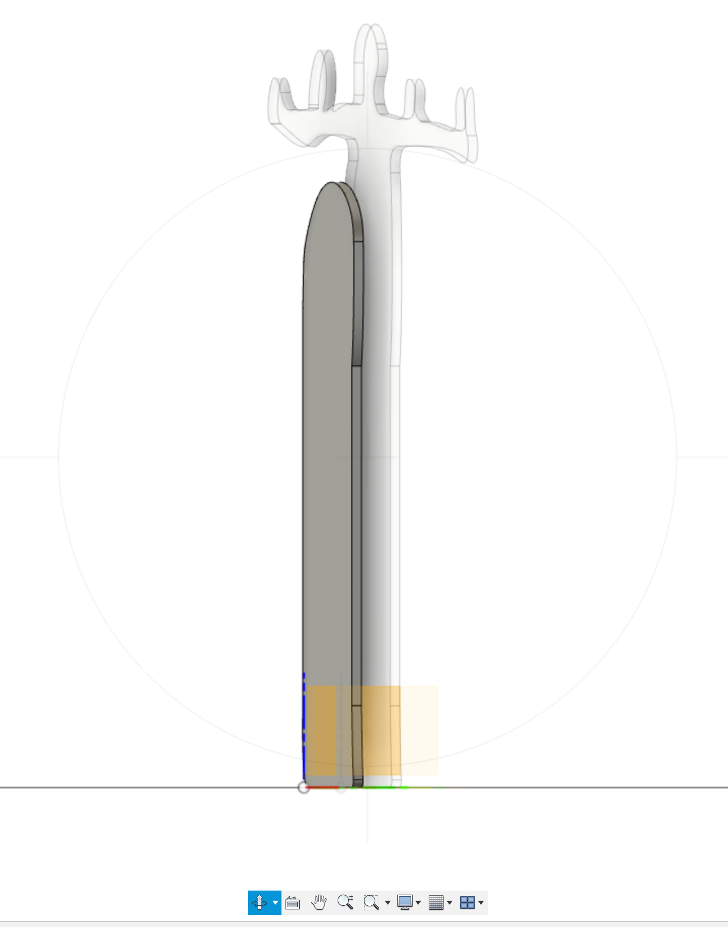
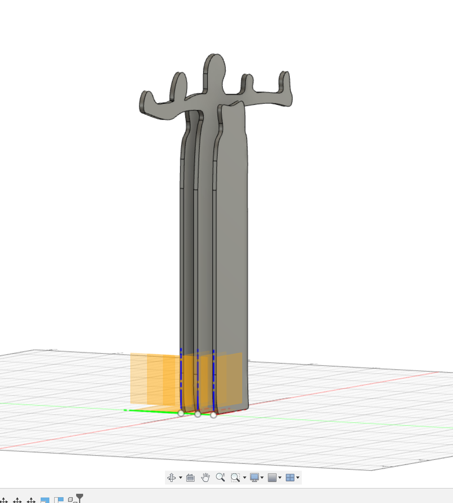
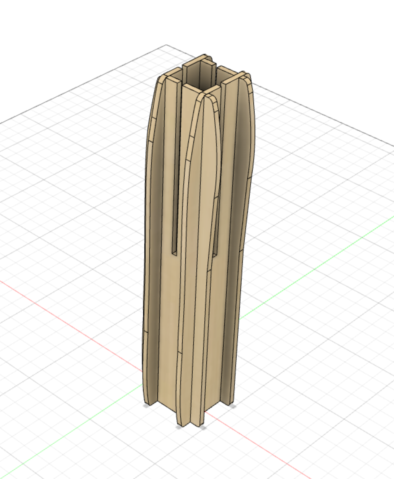
Sketch and extrude one of the 4 components. Copy it and paste new 3 times, so you have 4 components in total. Move the copies to their final position.
Extracting Material for the Joints Between the 6 Components That Form the Trunk.
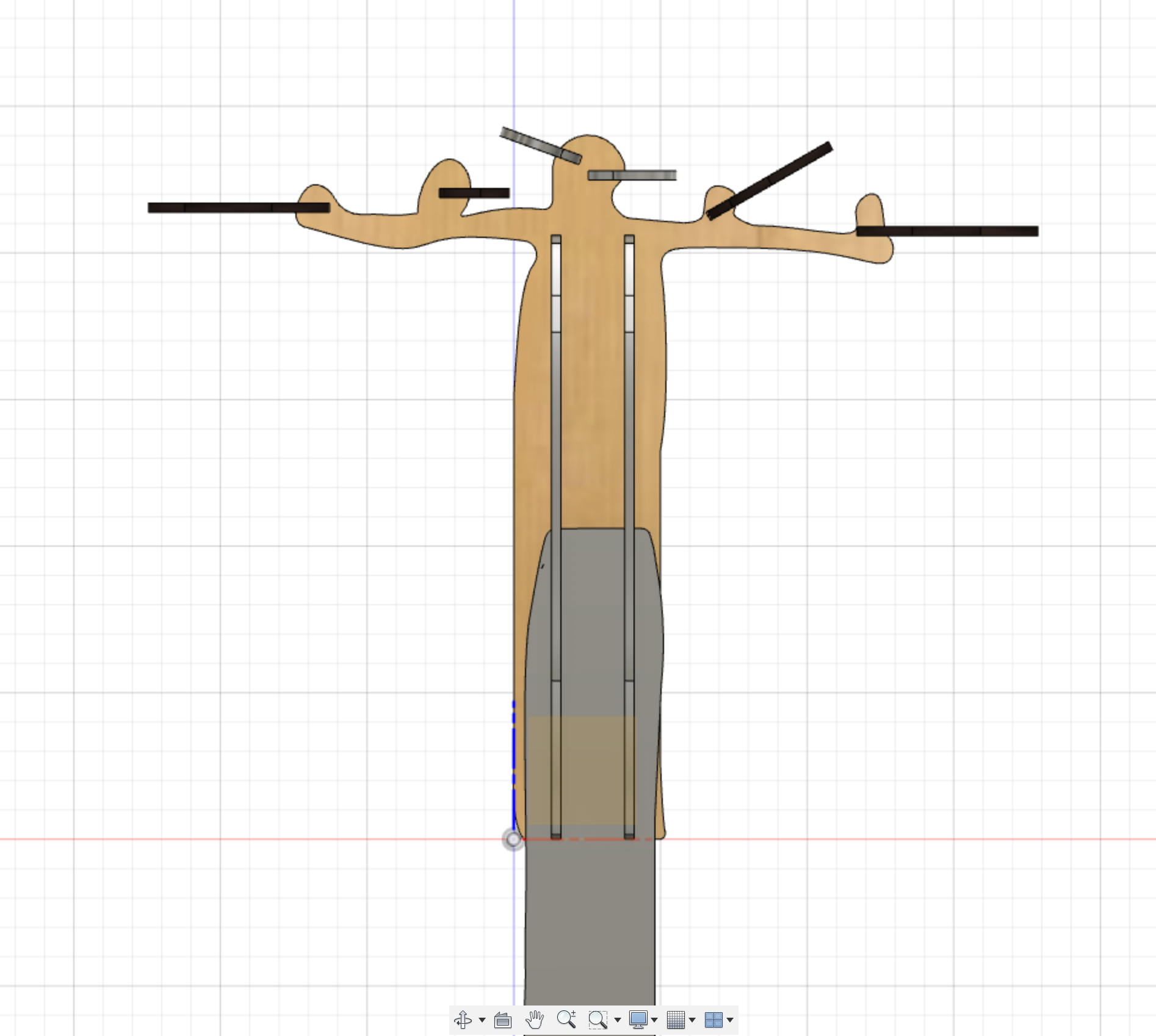
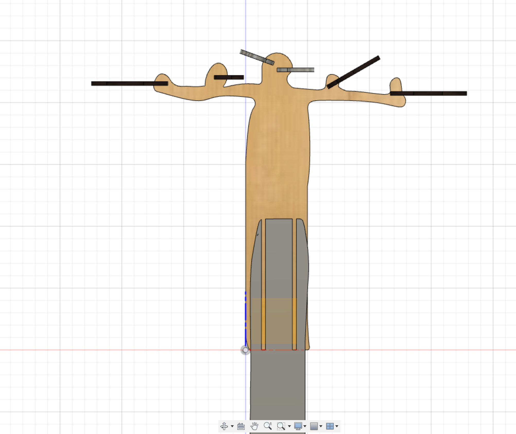
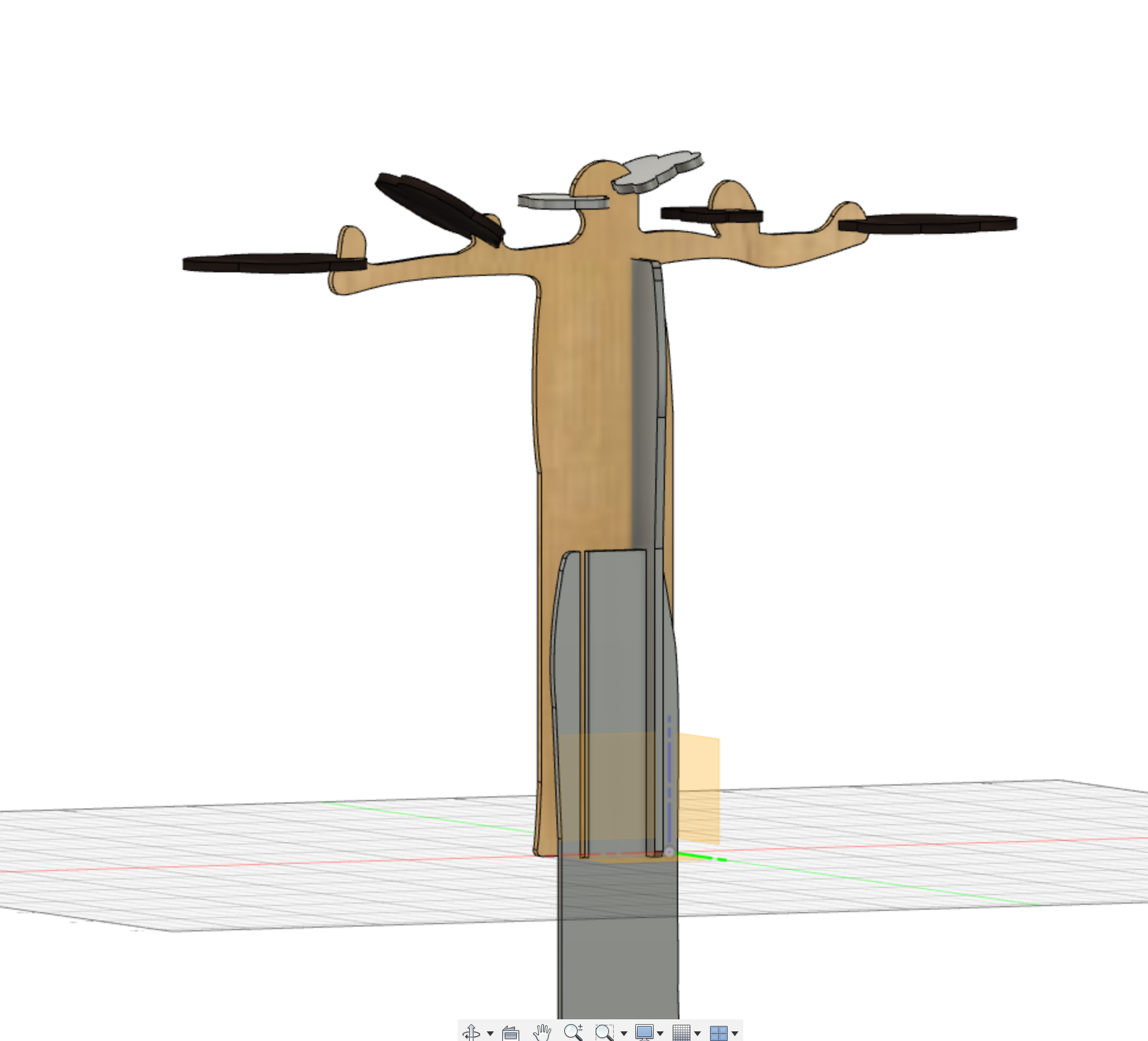
Create the joints between the 6 components that form the trunk extracting material in the same way that we did for the joints between the branches and the leaves.
Building Up the Base and Create the Joint With the Trunk.
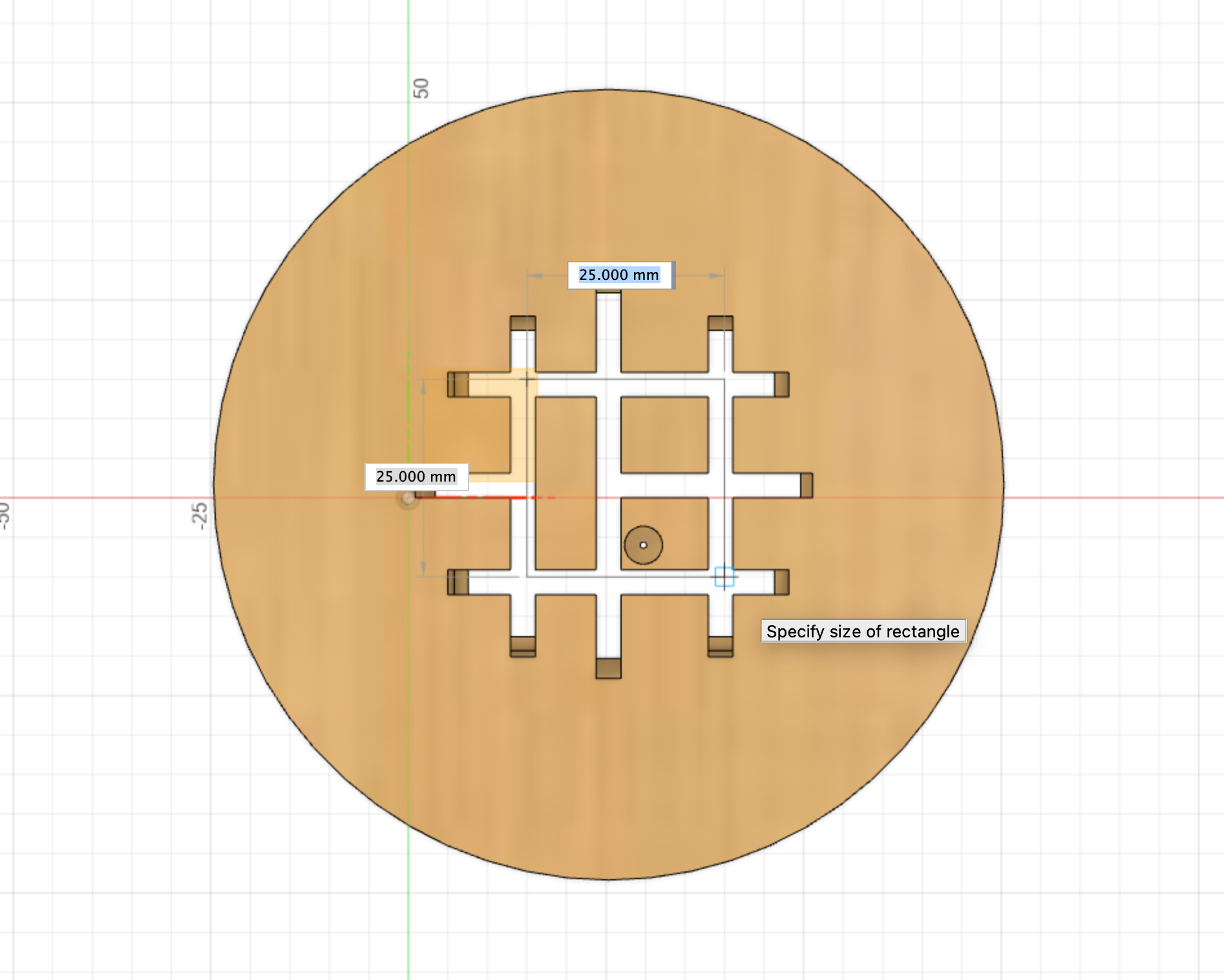
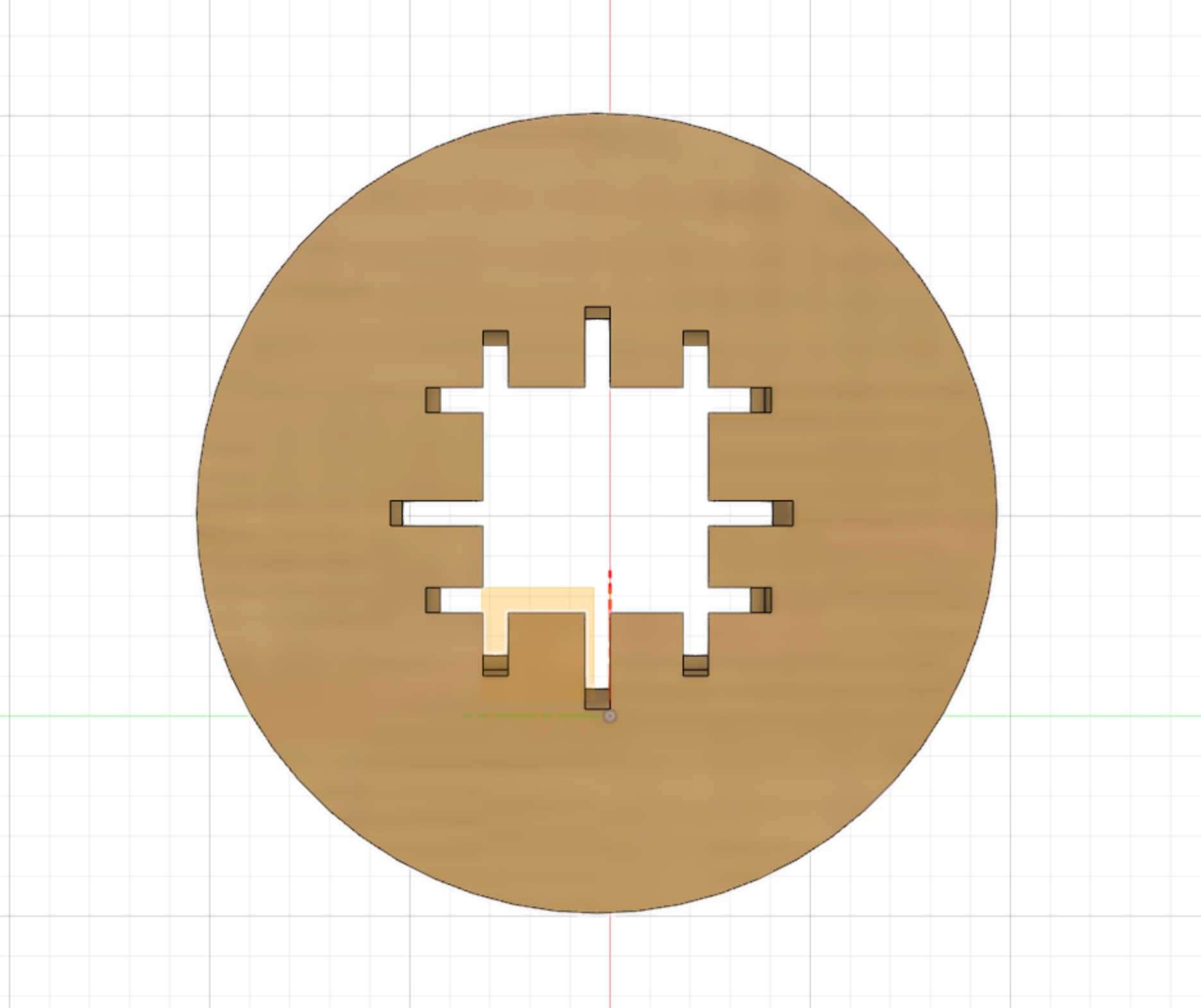
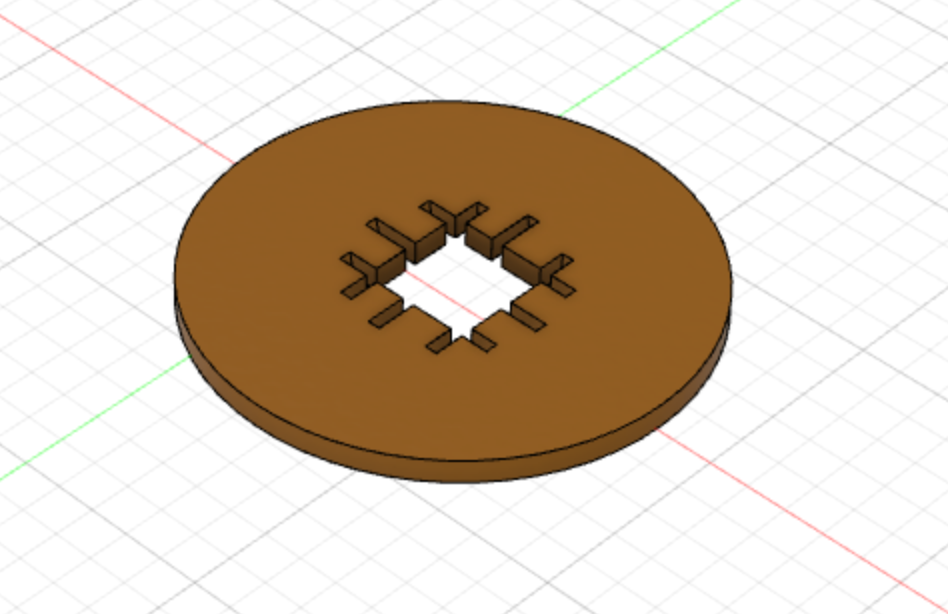
Sketch and extrude the base using the 2t parameter.
Create the joint with the trunk as we did before for the rest of the joints.
This time the base does not need to be reposition because we will be removing material only from the base and not the trunk.
The final piece will have 4 central parts that we do not need. Get rid
of them by creating a new sketch to cover these 4 peaces and then create a hole into the base to eliminate them.
Note: the image above has only 3 central extra part but yours should have 4.
Select the Materials and Colour for Each Component.
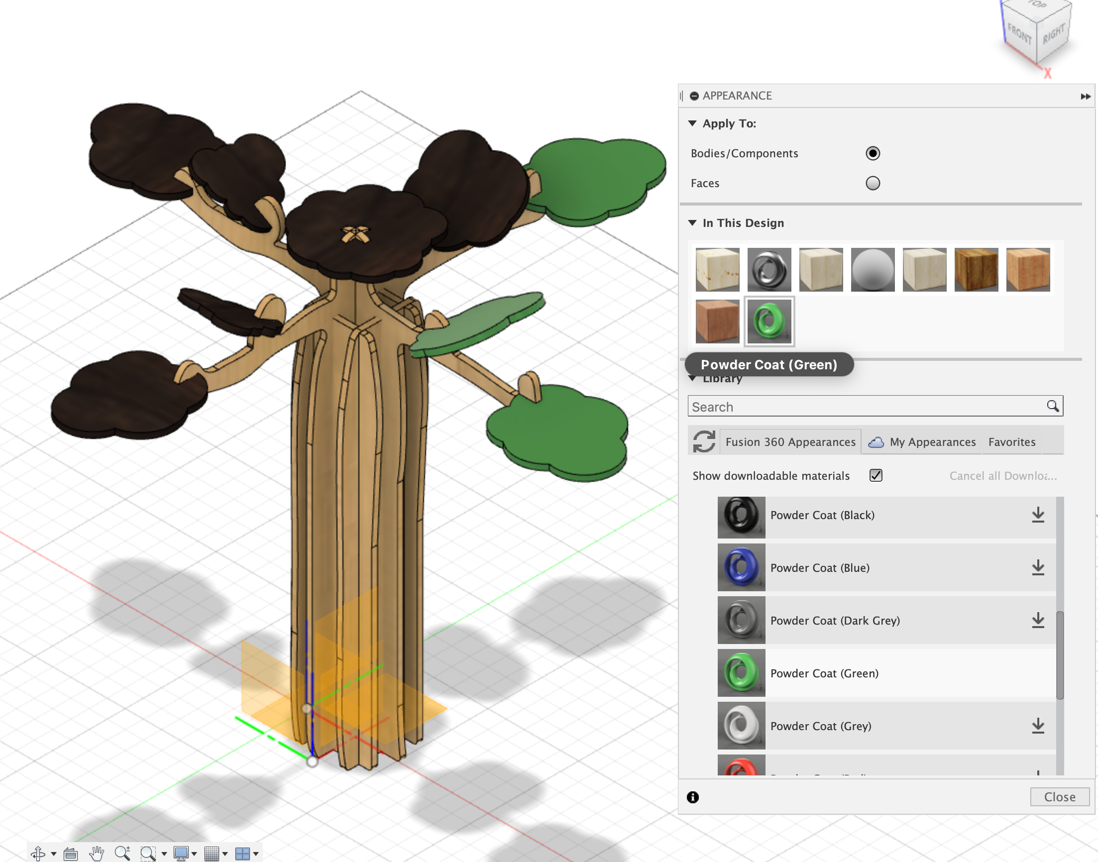
Go to modify - physical materials to chose materials and modify - appearance - paint - power coat smooth to change colours.
More info on how to change colours: https://forums.autodesk.com/t5/fusion-360-design-validate/custom-colors-for-appearance/td-p/5442504