Laser Controlled by Joystick Servos and Arduino
by CarlosVoltT in Circuits > Arduino
483 Views, 5 Favorites, 0 Comments
Laser Controlled by Joystick Servos and Arduino

In this tutorial, you will learn how to create a control system for a laser using a joystick, servos, and Arduino.

In this tutorial, you will learn how to create a control system for a laser using a joystick, servos, and Arduino.
During this step by step, I will guide you through the entire process, from initial setup to final programming, so you can control a laser using a joystick and servos. We'll explore how to connect the servos in conjunction with the Arduino, so you can move the laser in any direction you want.
This tutorial is designed to be accessible and exciting for everyone. Additionally, you'll discover how to write simple but effective code in Arduino to synchronize the movement of the servos with the joystick inputs, allowing you to aim and control the laser with ease.
You'll be able to use your joystick-controlled laser to create interactive light shows, precision games, or even for educational purposes.
Electronic components
Arduino mini pro

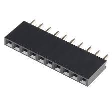
female pins
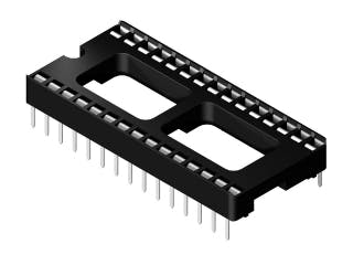
Socket for arduino nano
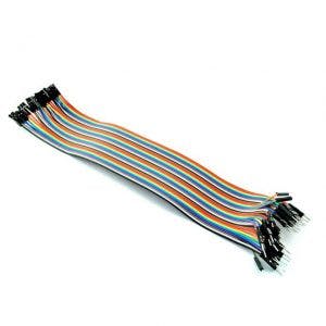
dupont cables
Laser Module ky-008
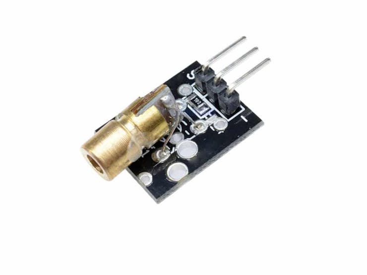
This module specially designed for Arduino easily, quickly and accurately emits a laser beam produced by this component.
It is a Laser Emitting Diode that operates at 5V and emits at a wavelength of 650nm.
Technical characteristics:
Operating voltage: 5V
Wavelength: 650nm
Power 5 mW
Color: Red
Material: PCB
Dimensions: 2.3×1.5×0.9cm
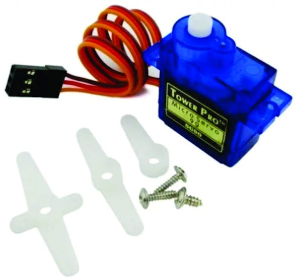
A Servo sg90
Characteristics
- Dimensions (L x W xH) = 22.0 x 11.5 x 27 mm (0.86 x 0.45 x 1.0 inches)
- Weight: 9 grams
- Weight with cable and connector: 10.6 grams
- Torque at 4.8 volts: 16.7 oz/in or 1.2 kg/cm
- Operating voltage: 4.0 to 7.2 volts
- Turning speed at 4.8 volts: 0.12 sec / 60º
- Universal connector for most radio control receivers
- Compatible with boards such as Arduino and microcontrollers that operate at 5 volts.
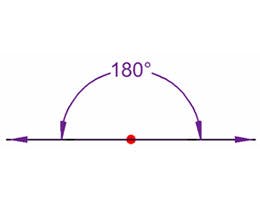
How to control a servomotor?
You can position the servo axis at various angles from 0 to 180º. The servos are controlled using a pulse width modulation (PWM) signal. This means that the PWM signal sent to the motor will determine the position of the shaft.
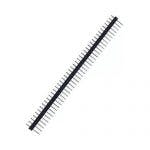
male pins
A ky-023 Joystick module

The Joystick module allows you to build a manual controller in 2 directions: X and Y. It also has the push-button function that is activated when pressing the Joystick.
It has two potentiometers each with its analog outputs for the direction (VRx-VRy) and a digital output for the button (SW). To read the position it is necessary to convert the analog values using a microcontroller ADC.
Used in robotics, control, automation, video game projects.
- Operating Voltage: 3.3 – 5V DC
- 2 Potentiometers
- 1 Push Button
Description:
Two-axis joystick sensor module by using PS2 rocker potentiometer, with (X, y) 2-axis analog output, (Z) 1 digital output button. With the Arduino sensor expansion board you can produce remote control and other interactive works. In addition, this product to allow customers to more easily with the arduino expansion board and other standard interfaces, in the design of the X, Y, Z axis of the circuit are separate tracks, the user can use ARDUINO's special line of 3 pins on the expansion board.
Product performance:
- Input voltage range: DC 3.3V to 5V
- Output signal: the module two-way analog output and a digital output interface, the output value corresponding to the biaxial offset (X, Y), the type of analog; keys that user press Z axis, its type is digital switch.
- Arduino controller, sensor expansion board connector can be programmed, complete with creative interactive works.
- Cross joystick is a 10K bidirectional resistance, with the rocker in different directions, the resistance tap with changing. This module uses 5V power supply, the original state of Press arrows in the opposite direction, read the voltage decreases, the minimum is 0 V.
PCB

Download gerber file –> ir alarm pcb
3D Parts
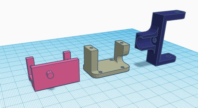
Download STL files –> Laser_gun_bracket_501701
Source Code
#include <Servo.h>

const int X_PIN_A0 = A0;       // Pin analógico para el eje X

const int Y_PIN_A1 = A1;       // Pin analógico para el eje Y

const int BOTON_PIN_12 = 12;   // Pin digital para el botón

const int LASER_PIN5 = 5;   // Pin digital para el control del láser

int estado = 0;

Servo servoX;

Servo servoY;

int servoXPosPrev = 90;     // Posición anterior del servo X

int servoYPosPrev = 90;     // Posición anterior del servo Y

int servoIncrement = 1;     // Incremento de posición para el serv

void setup() {

  pinMode(BOTON_PIN_12, INPUT_PULLUP);  // Configurar el pin del botón como entrada con resistencia pull-up interna

  pinMode(LASER_PIN5, OUTPUT);  // Configurar el pin del control del láser

  servoX.attach(10);   // Conectar el servo X al pin 10

  servoY.attach(11);   // Conectar el servo Y al pin 11

  Serial.begin(9600); // Velocidad del puerto serial

}

void loop() {

  // Leer los valores de los ejes X e Y

  int xValue = analogRead(X_PIN_A0);

  int yValue = analogRead(Y_PIN_A1);

  // Convertir los valores a la posición del servo (0 a 180 grados)

  int servoXPos = map(xValue, 0, 1023, 0, 180);

   // Convertir los valores a la posición del servo (70 a 180 grados)

  int servoYPos = map(yValue, 0, 1023, 70, 180);

  // Mover los servos suavemente

  if (servoXPos != servoXPosPrev) {

    if (servoXPos > servoXPosPrev) {

      for (int pos = servoXPosPrev; pos <= servoXPos; pos += servoIncrement) {

        servoX.write(pos);

        delay(5);  // Ajusta el retraso para controlar la velocidad del movimiento

      }

    } else {

      for (int pos = servoXPosPrev; pos >= servoXPos; pos -= servoIncrement) {

        servoX.write(pos);

        delay(5);  // Ajusta el retraso para controlar la velocidad del movimiento

      }

    }

    servoXPosPrev = servoXPos;

  }

  if (servoYPos != servoYPosPrev) {

    if (servoYPos > servoYPosPrev) {

      for (int pos = servoYPosPrev; pos <= servoYPos; pos += servoIncrement) {

        servoY.write(pos);

        delay(5);  // Ajusta el retraso para controlar la velocidad del movimiento

      }

    } else {

      for (int pos = servoYPosPrev; pos >= servoYPos; pos -= servoIncrement) {

        servoY.write(pos);

        delay(5);  // Ajusta el retraso para controlar la velocidad del movimiento

      }

    }

    servoYPosPrev = servoYPos;

  }

  // Leer el estado del botón

  bool botonEstado = digitalRead(BOTON_PIN_12);

if (botonEstado == LOW) {//Si el botón ha sido precionado se cumple esta condición

if(estado ==0){//Si la variable estado es igual a 0 se cumple esta condición

digitalWrite(LASER_PIN5, HIGH);

estado =1;//Asignamos el valor 1 a la variable "estado"

} else{

 digitalWrite(LASER_PIN5, LOW);

 estado =0;

  }

while(botonEstado == LOW){

botonEstado = digitalRead(BOTON_PIN_12);//Leemos el estado del botón nuevamente para ver si sigue precionado

    }

  }

  // Mostrar los valores en el terminal serial

  Serial.print("Eje X: ");

  Serial.println(xValue);

  Serial.print("Eje Y: ");

  Serial.println(yValue);

  Serial.print("Botón: ");

  Serial.println(botonEstado);

  delay(100);  // Leve pausa entre las lecturas

}