Laser Communication Device (Arduino Project)
by Mechanical Attraction in Circuits > Arduino
14412 Views, 33 Favorites, 0 Comments
Laser Communication Device (Arduino Project)
)
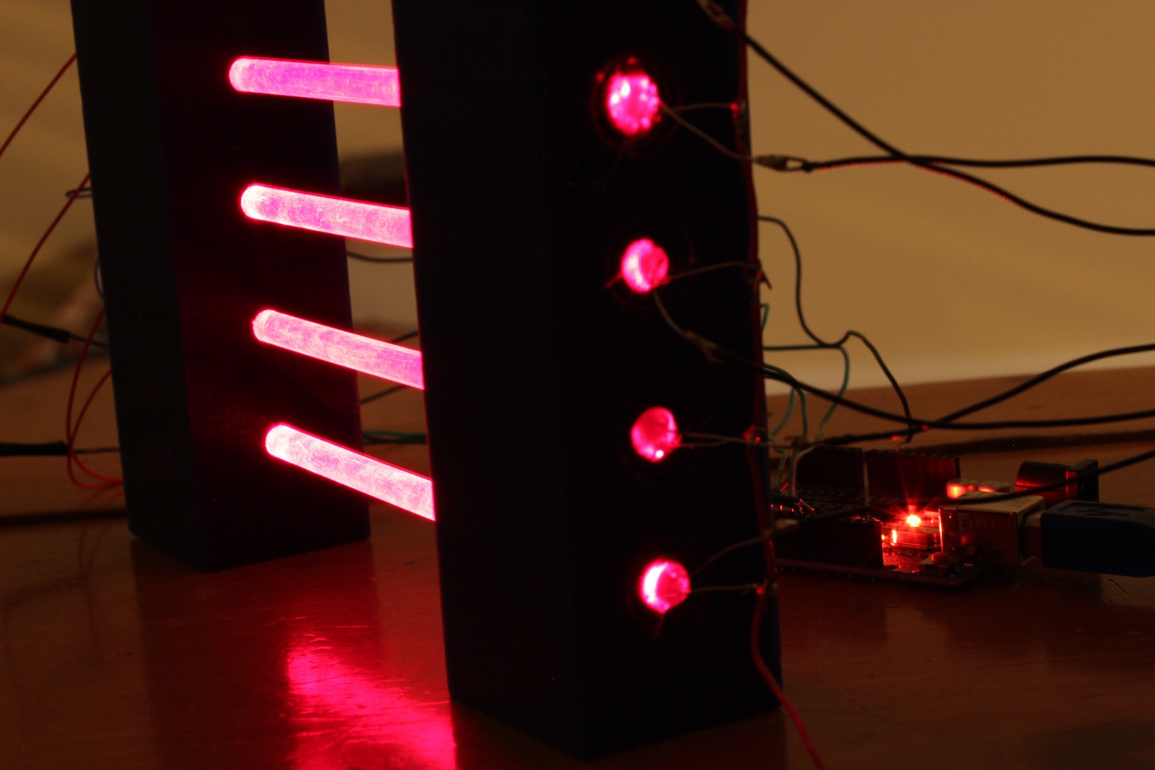
This instructable describes how to make a simple device that transmits text via laser diodes and photo resistors. The attached video describes the process in detail. This is the written version of that.
What you need is:
2x Arduinos, 5x 5 volt 6 mm diameter laser diodes, 5 photo resistors, 5x 1/4 inch diameter 6 inch long acrylic tubing, material for housings (I used two 1x1x6in wax blocks), and computers with supporting software.
Housing Construction
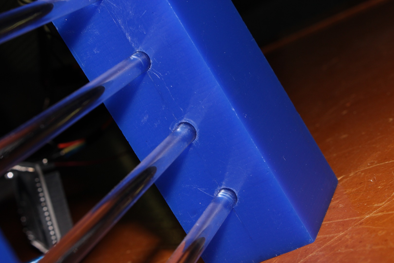
To build the housing I used two rectangular blocks of wax, which makes for easy drilling. The material, spacing and sizes are arbitrary. Attached is a PDF of my set up. Note that this is the original design, when I used entire laser pointers instead of laser diodes. The extra 7/16 inch holes drilled in the left block can be ignored if using laser diodes. The acrylic rods are 6 inches long.
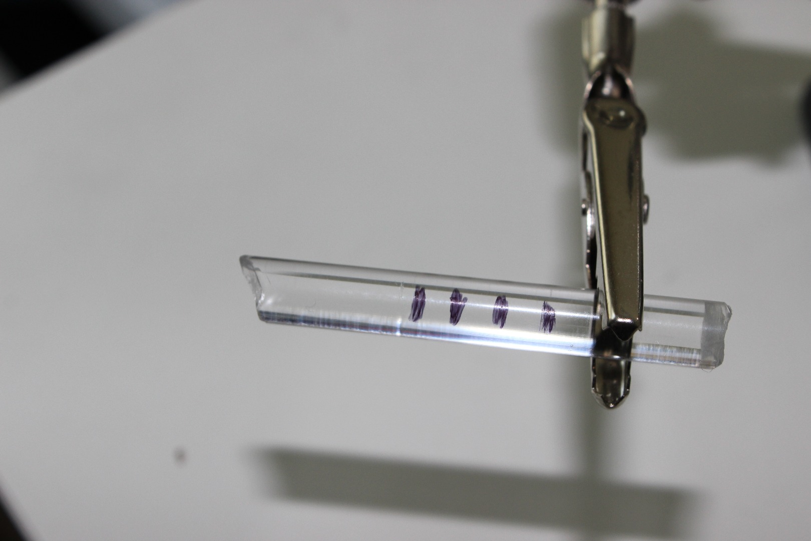
If you are using wax like myself, after you drill the 1/4 inch holes you will find that the 1/4 inch diameter rods will have difficulty fitting. To fix this cut an end off an acrylic rod at an angle and make marks for desired depth (roughly 1/2 inch). Then insert with a twist to shave in inside walls of the hole to accommodate the acrylic rods. The tool is shown in the picture above. After doing so the rod should have a snug fit at the end of the shaved length.
Next one block will need to have the laser diodes hot glued in. Make sure that they are pointed in the correct direction, directly out of the holes within the wax block. I did this by pushing an acrylic rod into the hole so that the diode can sit flat on top while the gluing took place.
This last step will then be repeated on the other housing block except using the photo resistors.
Downloads
Wiring
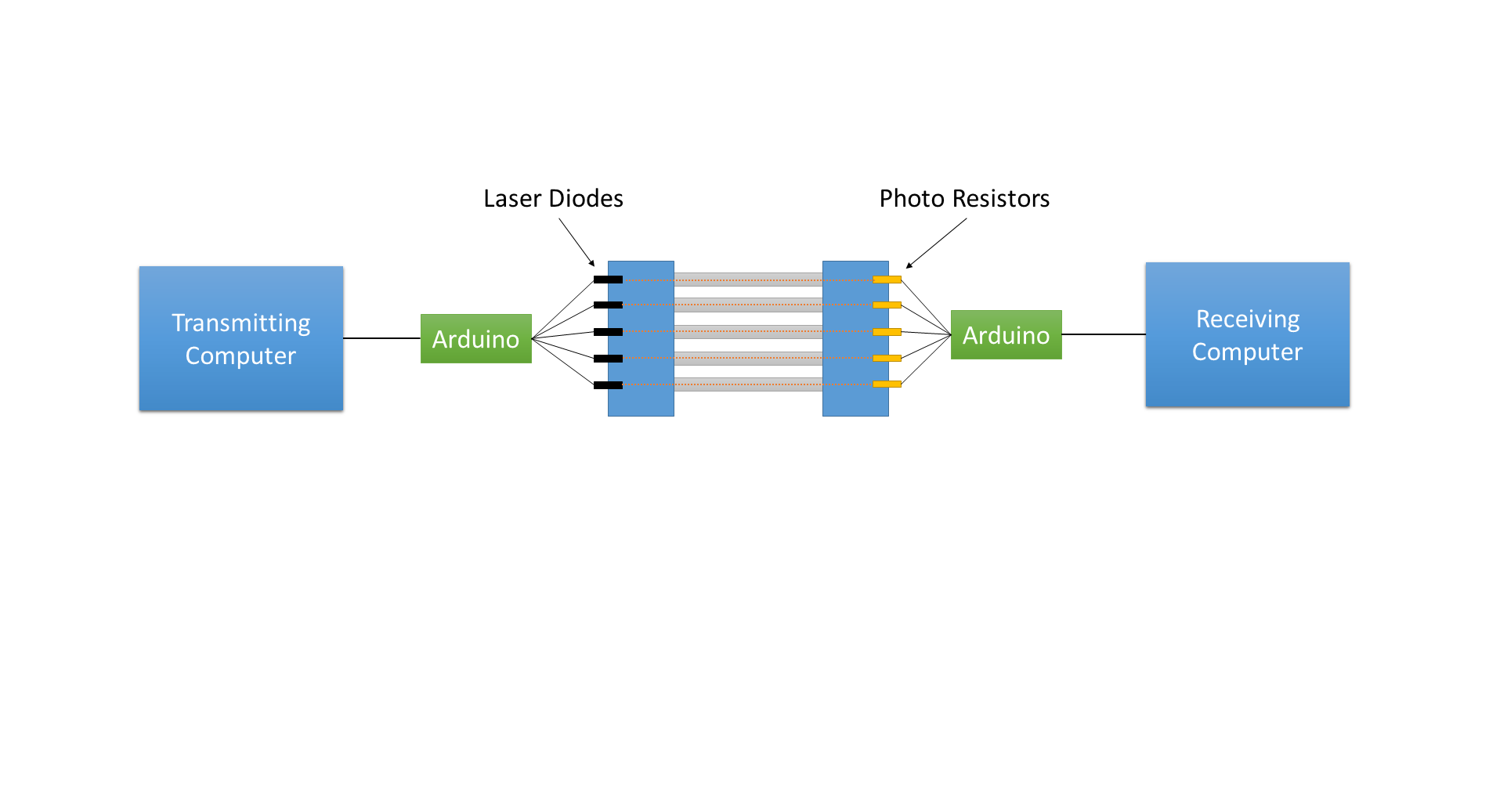
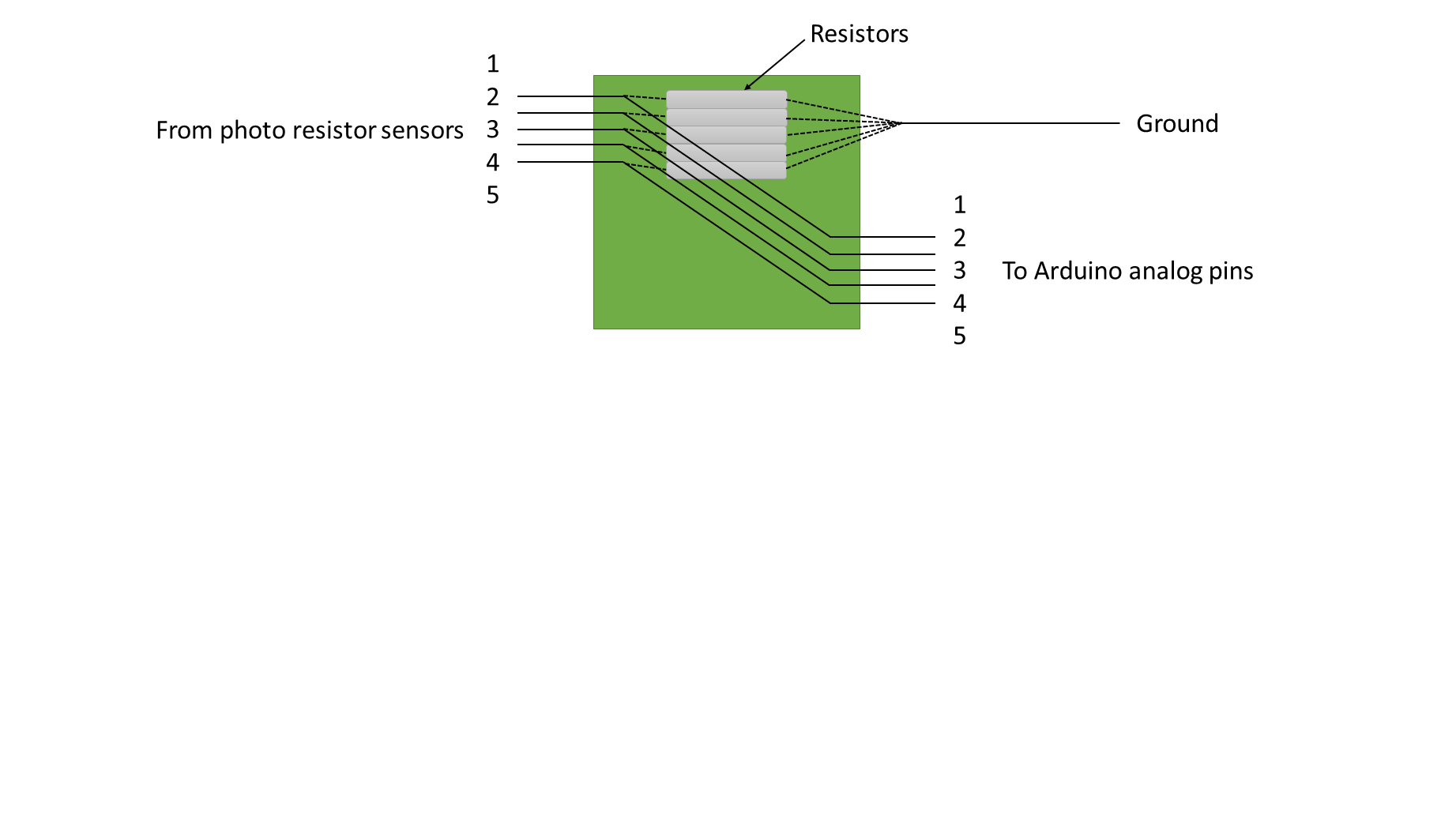
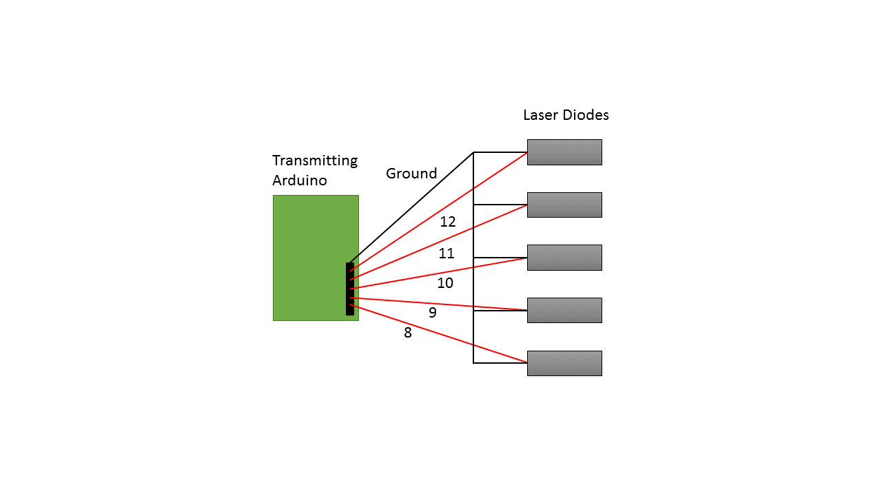
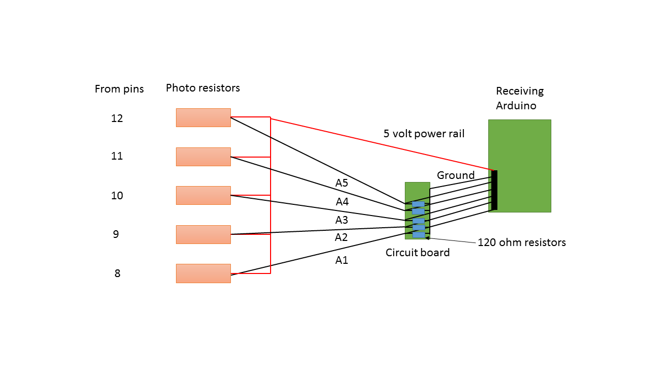
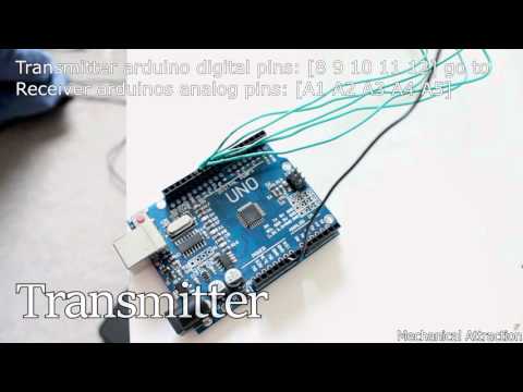
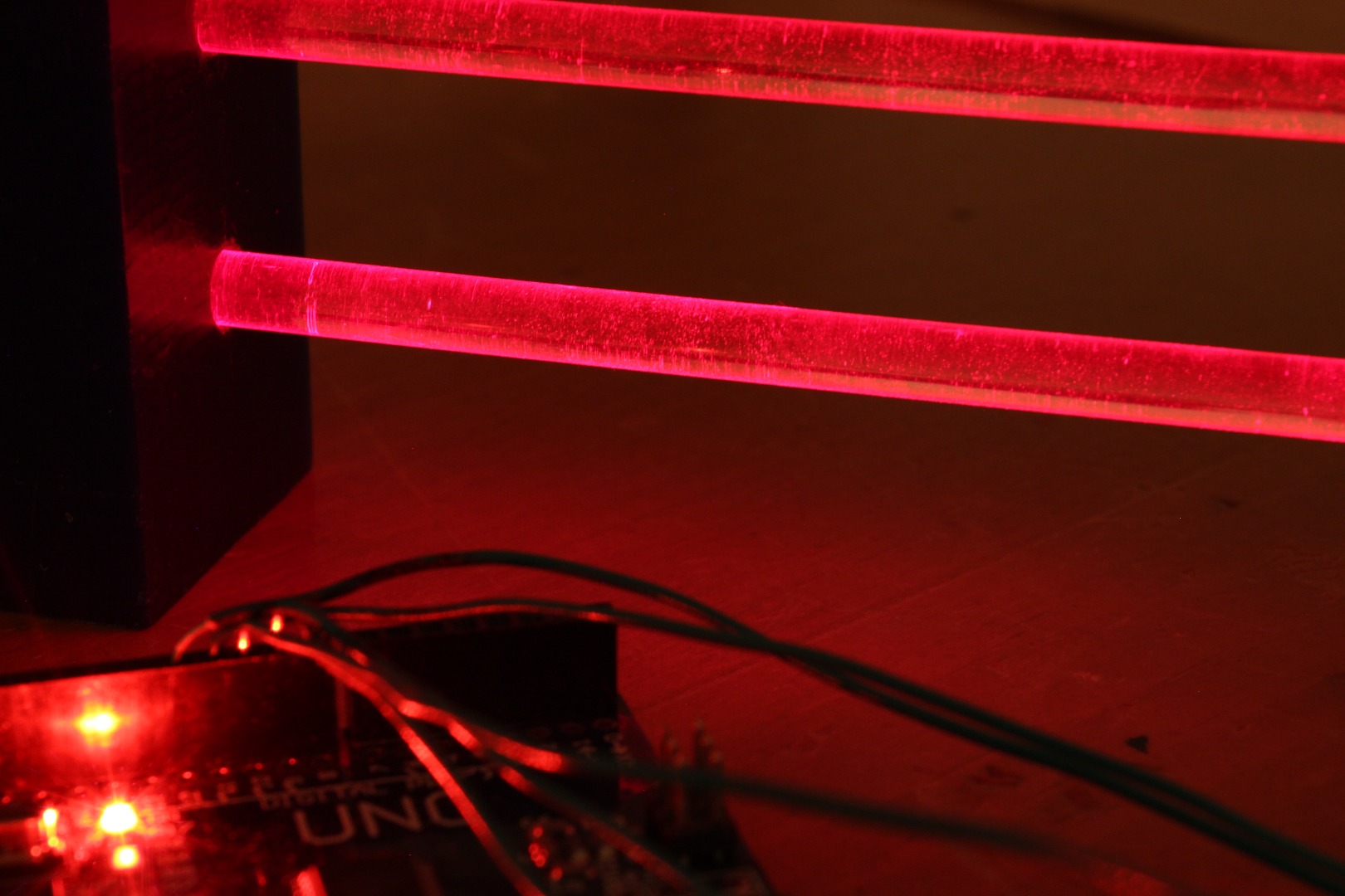
Next the wiring. For the transmitter side each arduino pin will have its own laser diode which will correspond to its own photo resistor. The laser diodes all will share a single ground. Refer to the provided image of the transmitting arduino above. The receiving side is slightly different, where as there is a single power supply rail. After the photo resistors, the wires will be split through a circuit board. Refer to the images provided for details. The only tedious part is making sure that on the wiring is good on the small circuit and that the correct laser pins [8 9 10 11 12] correspond to the receiving arduino pins [A1 A2 A3 A4 A5].
Arduino Programing
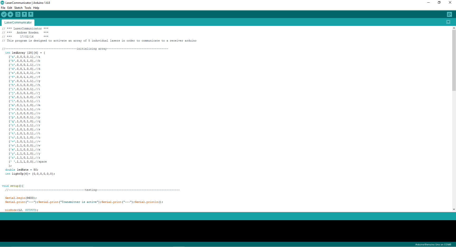
The programs are provided, but below is how we made it work. Once downloaded onto the arduino boards, open the serial monitor (for both arduinos), type and send your message. The receiving arduino will then write the received message.
Transmitter:
1. Array is declared to serve as a library to reference against later.
2. Waits for user input as a string.
3. Receives input and breaks down the message into each individual character and records them along with the total length.
4. Runs through each individual character until the message length is reached.
1. For each letter, a loop runs through the array until the character entered is equal to the character in the array. 2. The binary values that are associated with the character in the array are saved to a temporary array which is then outputted.
Receiver:
1. Array is declared to serve as a library to reference against later.
2. Waits for laser input.
3.Once laser input is received, a “snapshot” of the active lasers is saved to a temporary array.
4.This temporary array is compared to the reference array created in step 1.
5.Once a match is found, the character associated with that input is displayed
6. This process is repeated until all laser tubes are identified as on. At this point the program acknowledges the end of a transmission and skips a new line.
Finished
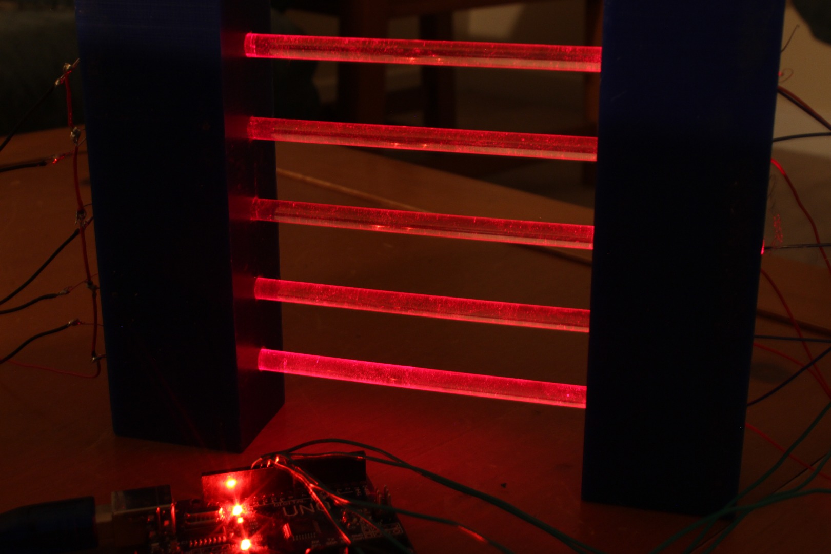
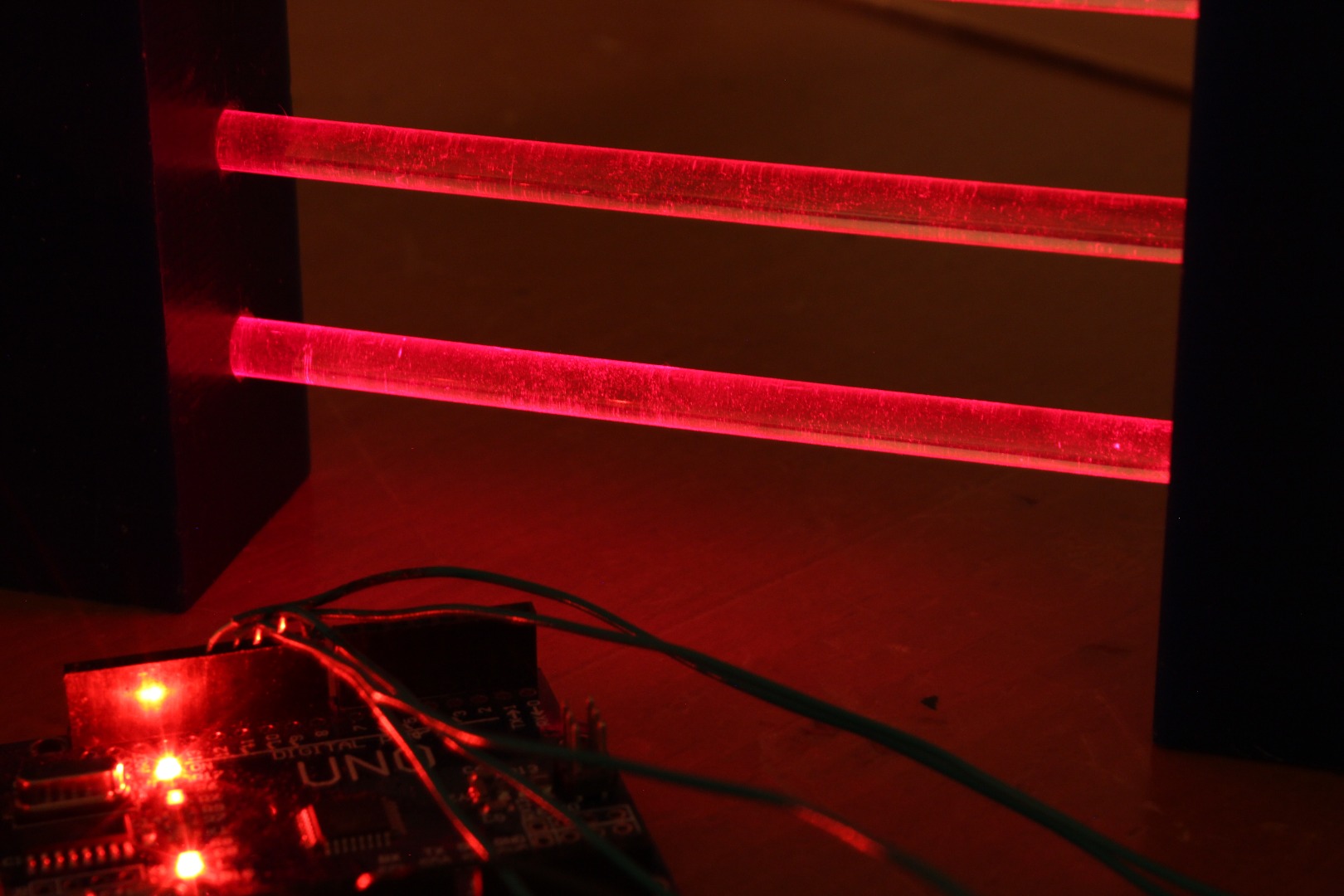
The device now is complete.