Larson Loop
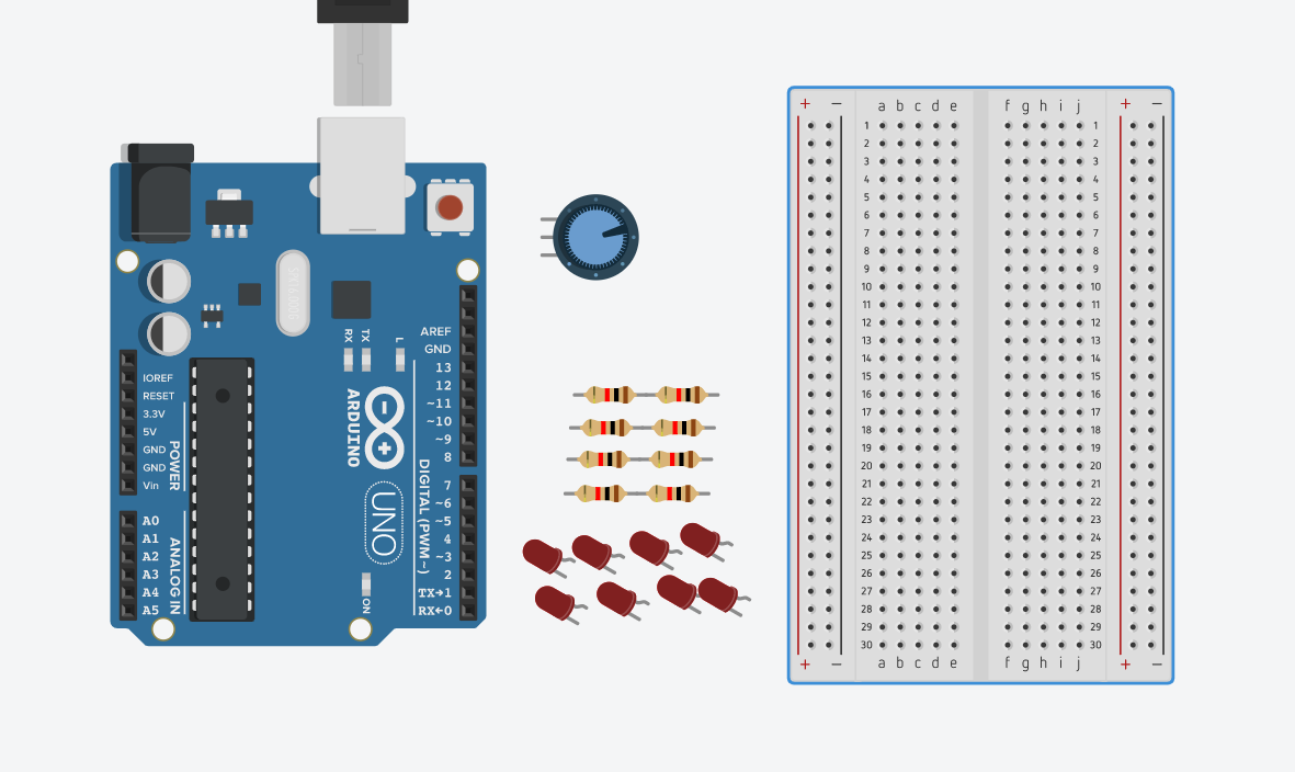
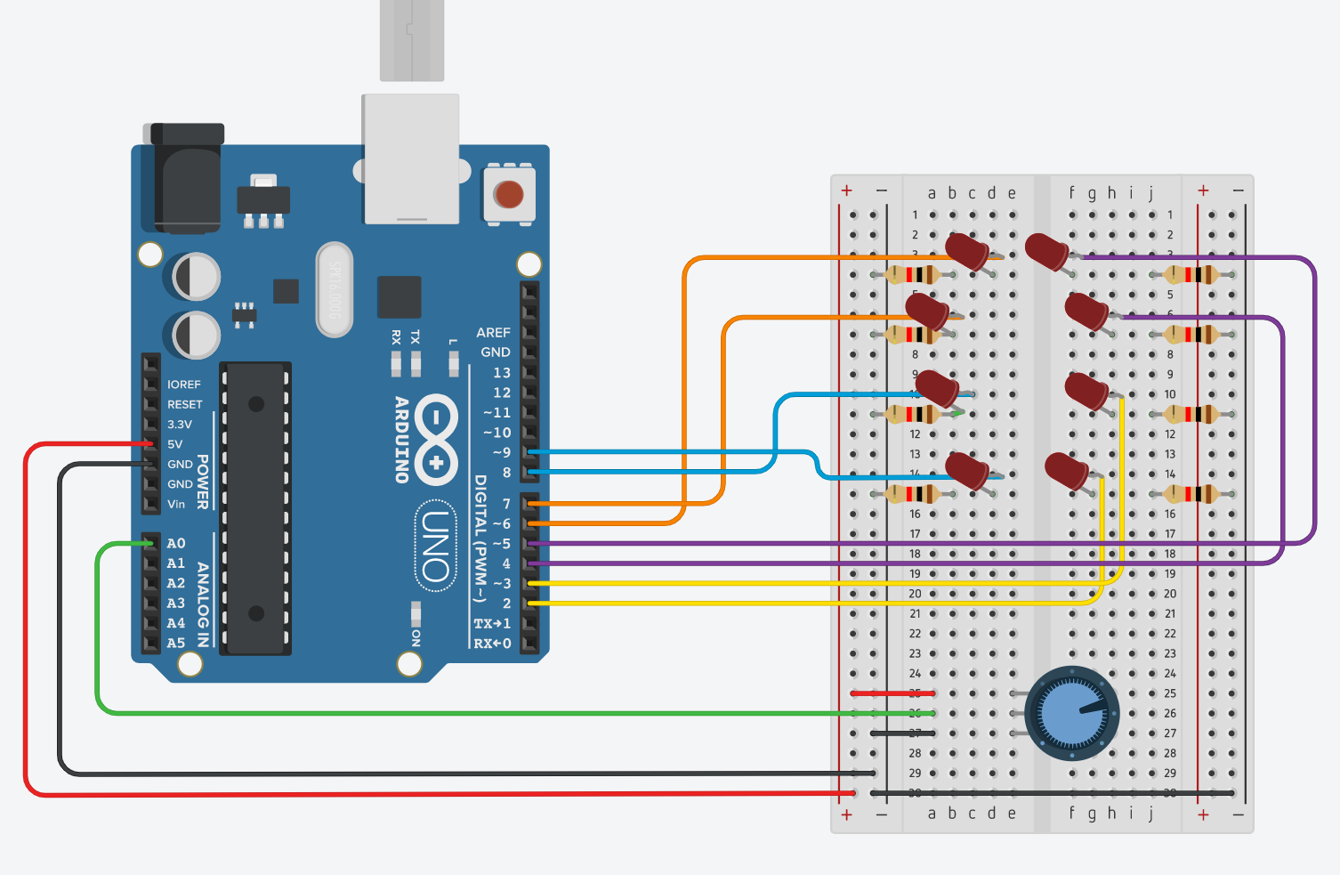
This project is called the Larson Loop which was inspired by a device called a Larson Scanner.
The idea is that you have multiples LEDs in a loop where light from the LEDs looks as it is going in a loop. In addition, a potentiometer is used to change the direction and speed of the Larson loop as well
Supplies
For this project, it requires:
- 8 1k ohms resistors
- 15-ish jumper wires
- Arduino Mega (or any Arduino with 8+ PWM pins)
- 10k ohm potentiometer
- 8 LEDs
+5V and GND

The first step is to connect the ground (GND) and power (+5V) from the Arduino to the breadboard. GND to the columns with the negative sign of the breadboard. +5V to the columns with the positive sign of the breadboard.
Connect the LEDs and Resistors
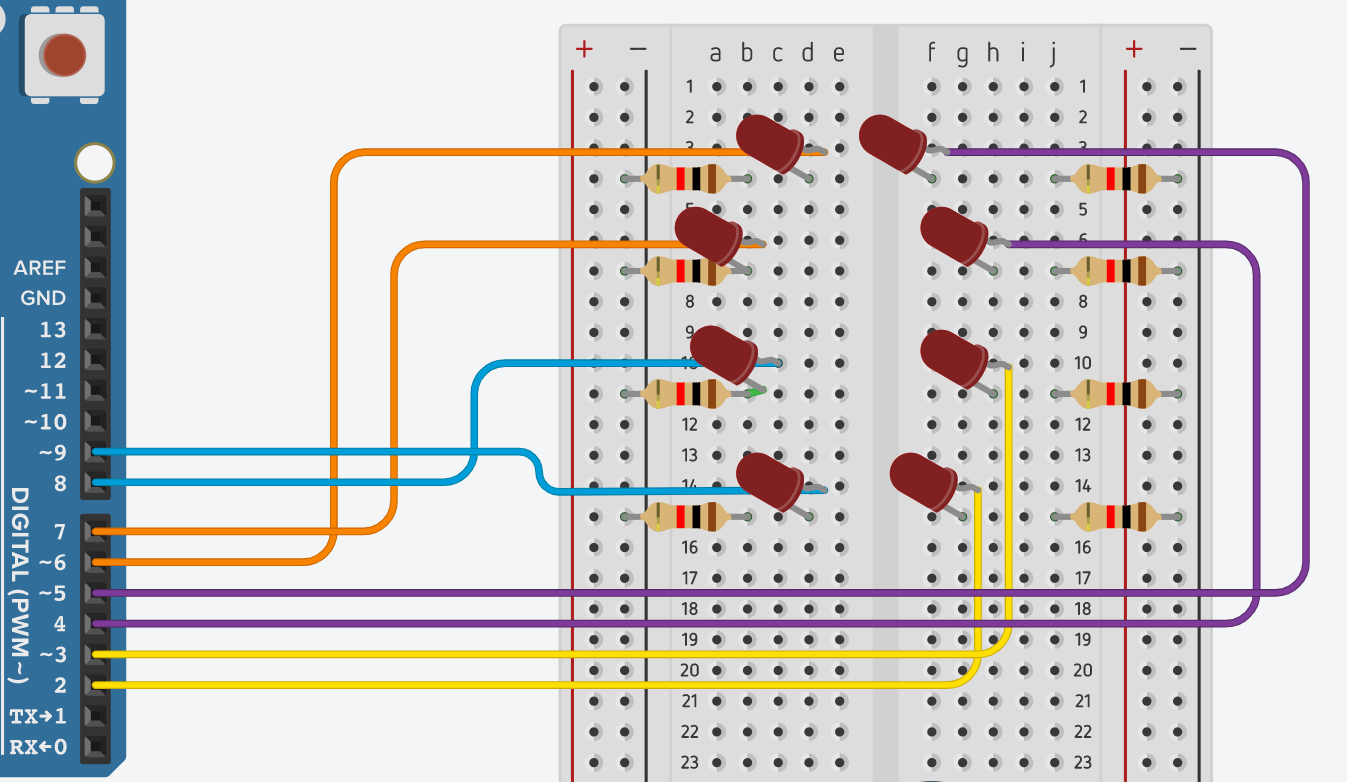
The next step is to set up the LEDs and resistors onto the breadboard. Have each resistor connect to the cathode pin or the shorter pin of the LED and to the GND just like in the diagram. Then connect a jumper cable to each anode pin or longer pin of the LED and to a PWM pin just like in the diagram.
Keep in mind, that I used an Arduino Mega which has PWM pins for pin 2-13 and not an Arduino Uno.
Connect the Potentiometer

After that, connect the potentiometer to the breadboard. Have +5V go on one end of the potentiometer and have GND go on the other end of the potentiometer. Then connect a wire from the middle pin of the potentiometer to the A0 pin of the Arduino.
Arduino Code
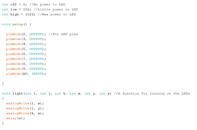
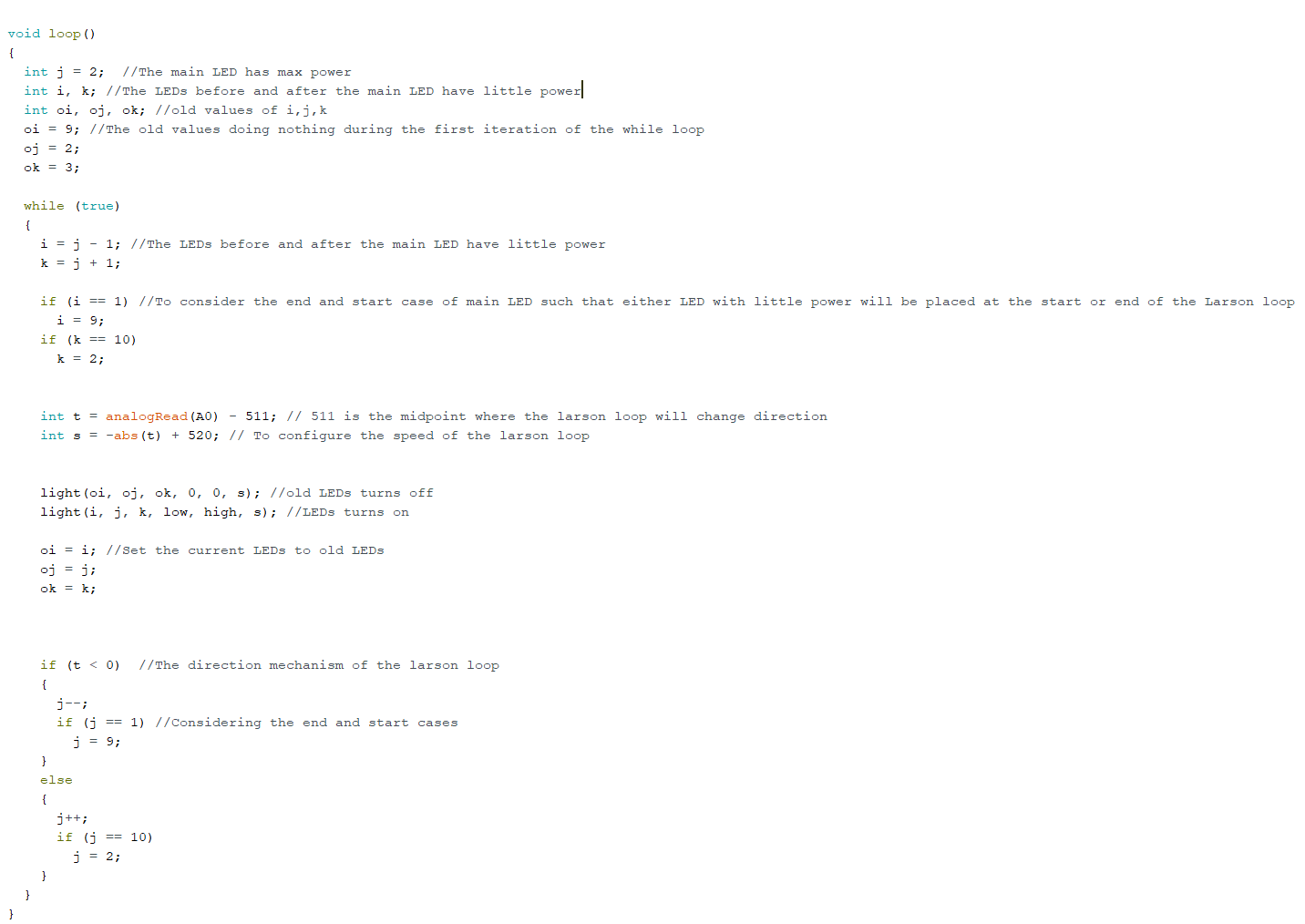
Copy the code onto your Arduino software. The comments on the code describe its functionality along the lines.
Downloads
Testing & Done
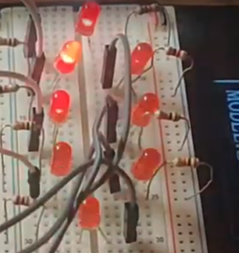
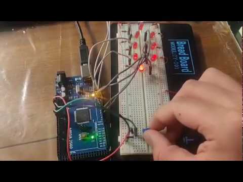
Once you are done setting your program and circuit. Run the code. You should see that the LEDs will be going in a loop. You can change its direction and speed by adjusting the knob of the potentiometer.