Laptop Mod: the Pop-Up CPU Monitor Display
by TeethutL in Circuits > Arduino
2465 Views, 18 Favorites, 0 Comments
Laptop Mod: the Pop-Up CPU Monitor Display
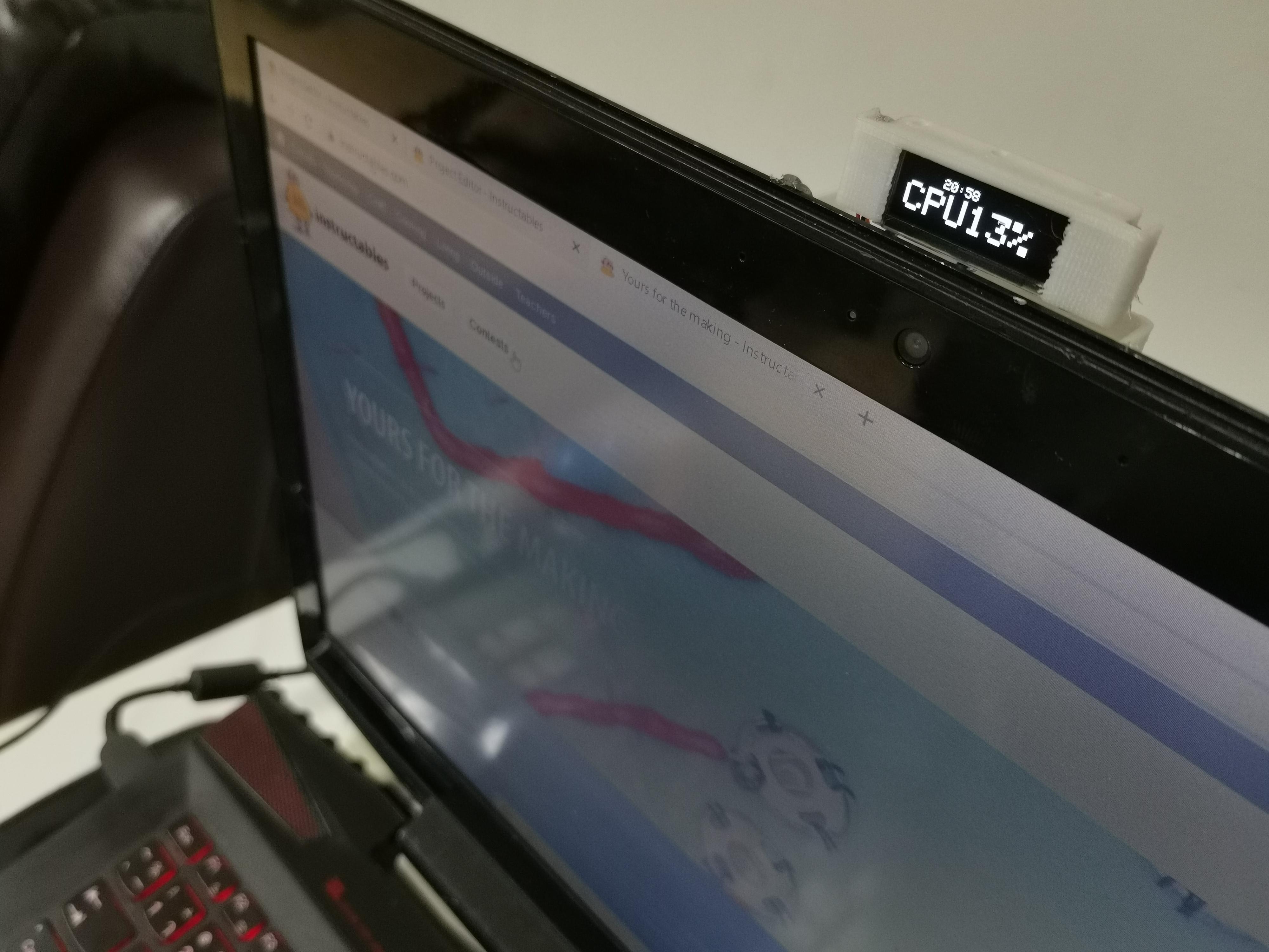
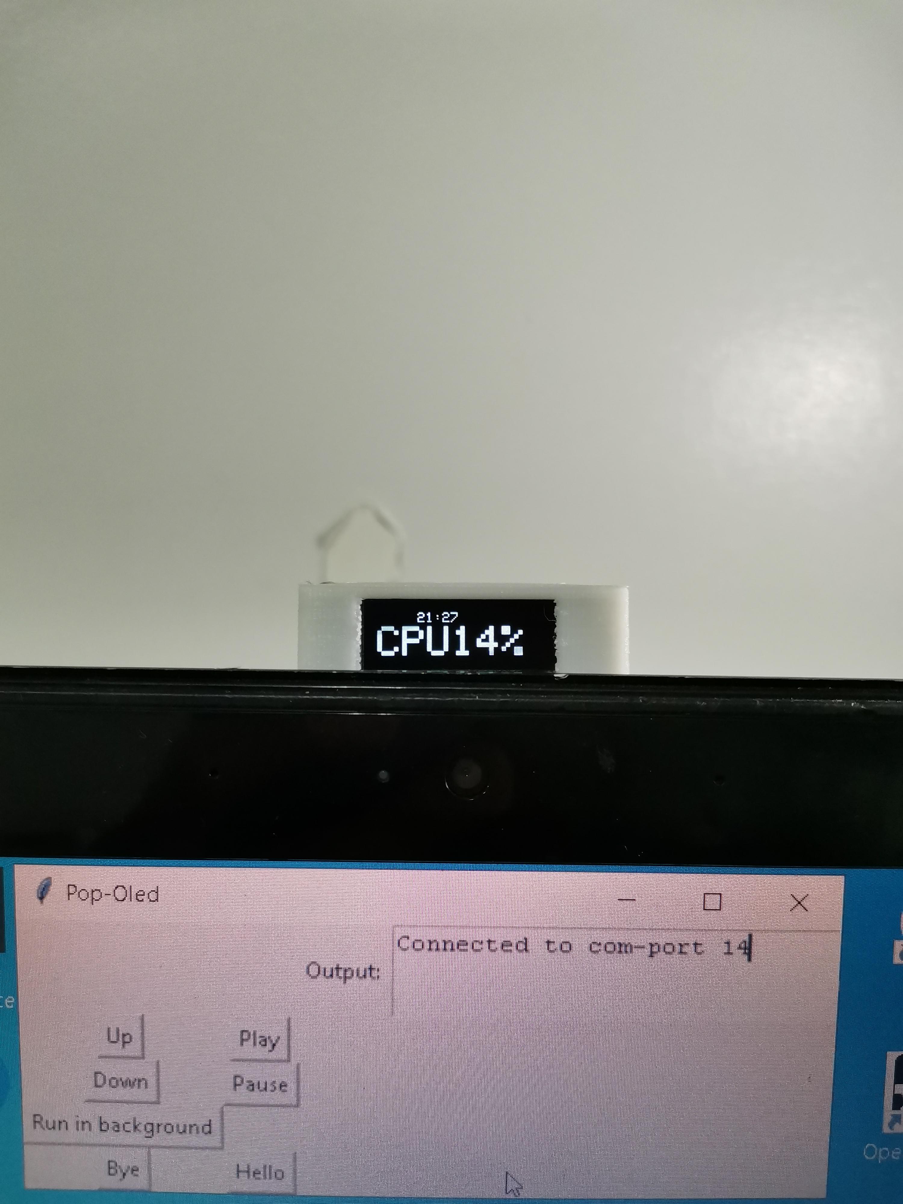
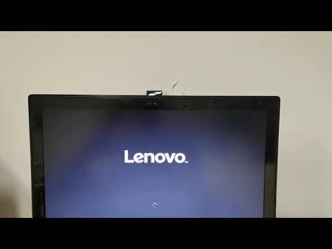
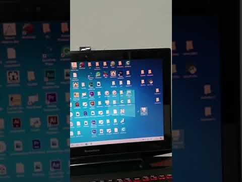
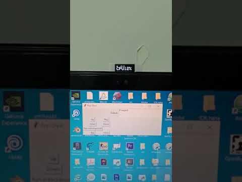
I wanted to add some fancy features to my boring laptop. I got inspired when I saw a pop-up-camera-smartphones, and some laptops that have a secondary display. So, I decided to mod my own laptop with a homemade mini pop-up display, that could display something cool.
This tiny display will pop-up whenever I turn-on my laptop. And when it is connected to the laptop, it will show real-time CPU usage percentage and time.
In this instructable, I will share with you how I made it so that you can make your own.
Supplies
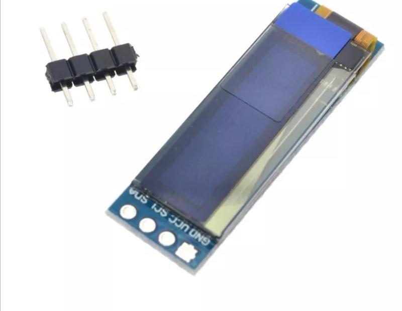
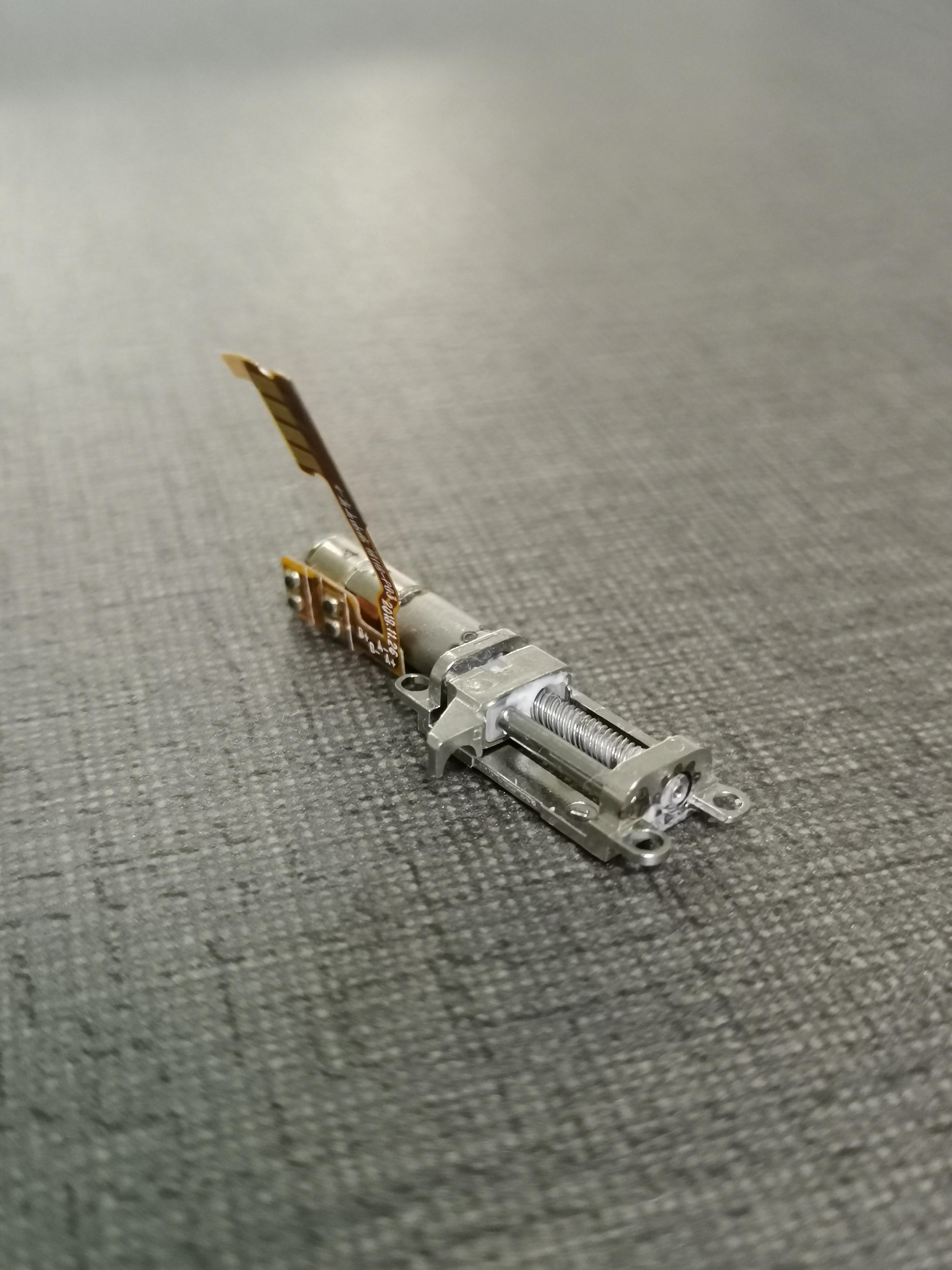
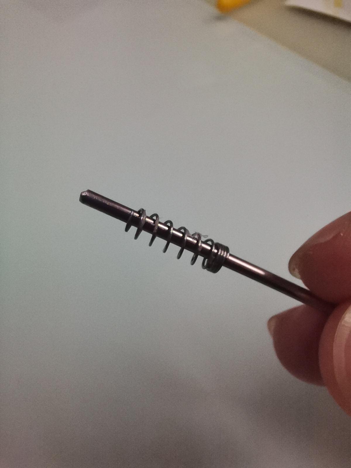
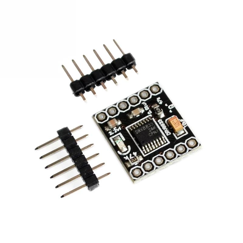
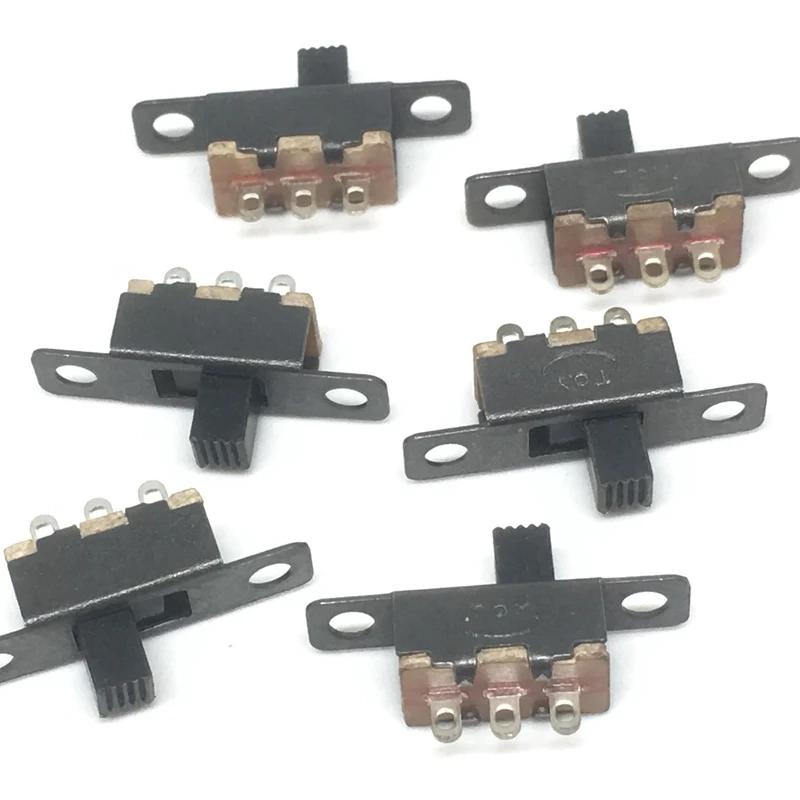
- 0.91" OLED Display
- 2mm rod
- Wires wrapping cable(30AWG solid core)
- Tiny stepper motor
- Dual h-bridge module(DRV8833)
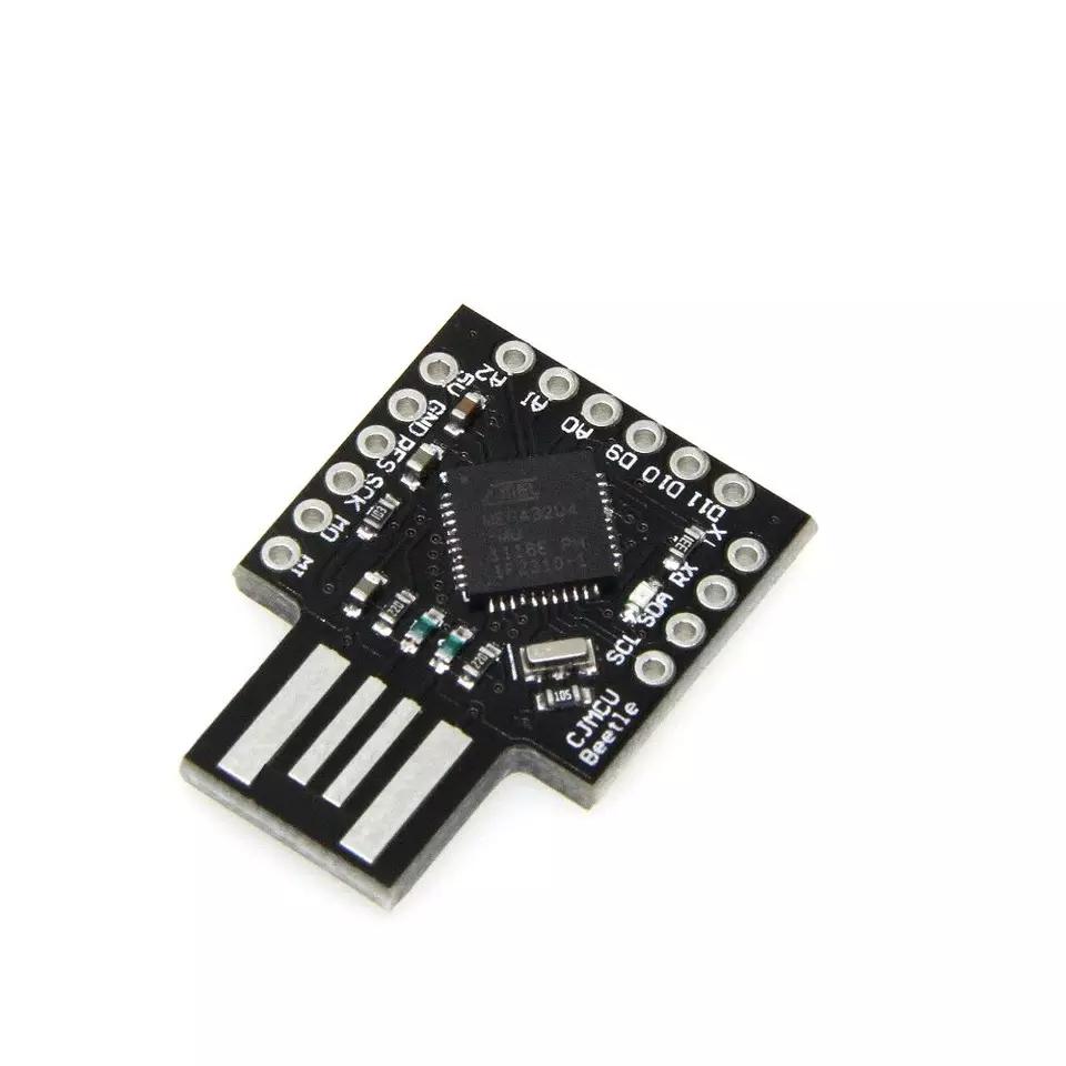
- USB Atmega32u4 board
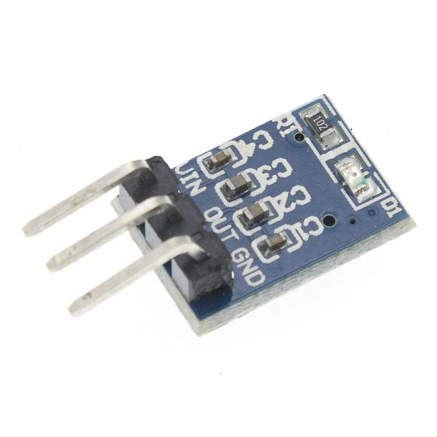
- Voltage regulator(3.3v)
- A spring from a cheap pen
- micro on-off switch
How It Works?
Pop-up camera smartphones use a very small stepper motor in combination with a gearing system and threaded rod, to add more torque and to be able to move up and down linearly. These tiny stepper motor also exists in DVD trays and some moving part cameras.
I use a small Arduino-compatible board based on Atmega32u4 MCU as a brain since it has native usb support, which means the MCU can communicate with the laptop without the need for an additional USB chip. This keeps its size small. Perfect for our project.
I have made a program that will run on the laptop, it will get the CPU usage data and time, then send it to the arduino board over usb port(COM). The Arduino board then tell OLED to display the data recieved.
Driving the Stepper Motor
The motor has a built-in gearing and a 12mm linear stroke.
The resistance per phase of the motor is about 14.5ohm.
It is a bipolar stepper motor(4-wires)-consists of 2 coils inside, which is why we need 2(dual) H-bridges to drive a single stepper motor.
The resistance per coil can affect the current draw of the motor. Too much current can damage the motor by overheating the coils. The driver that I choose can't limit the current, so I power through a 3.3v regulator to lower the maximum current instead of using direct 5v from the usb. With Ohm's Law, we can calculate the maximum current- current(A)=voltage(V)/resistance(ohm), which in this case is about 0.2A(200mA).
Hiding the Wires
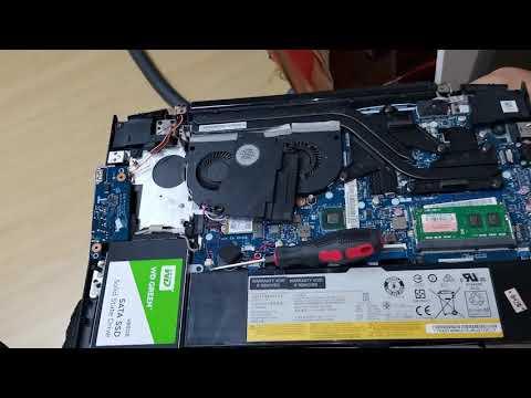
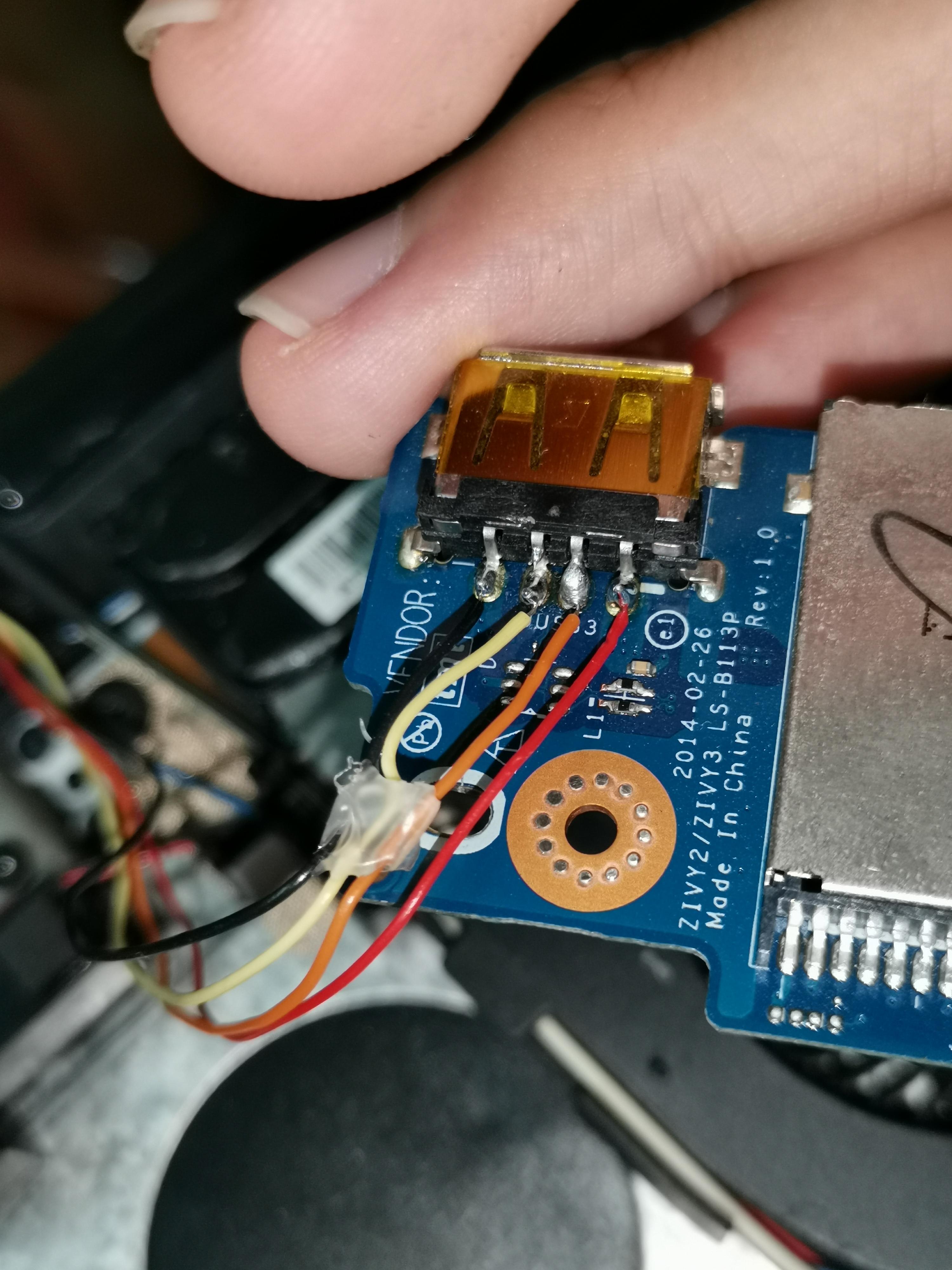
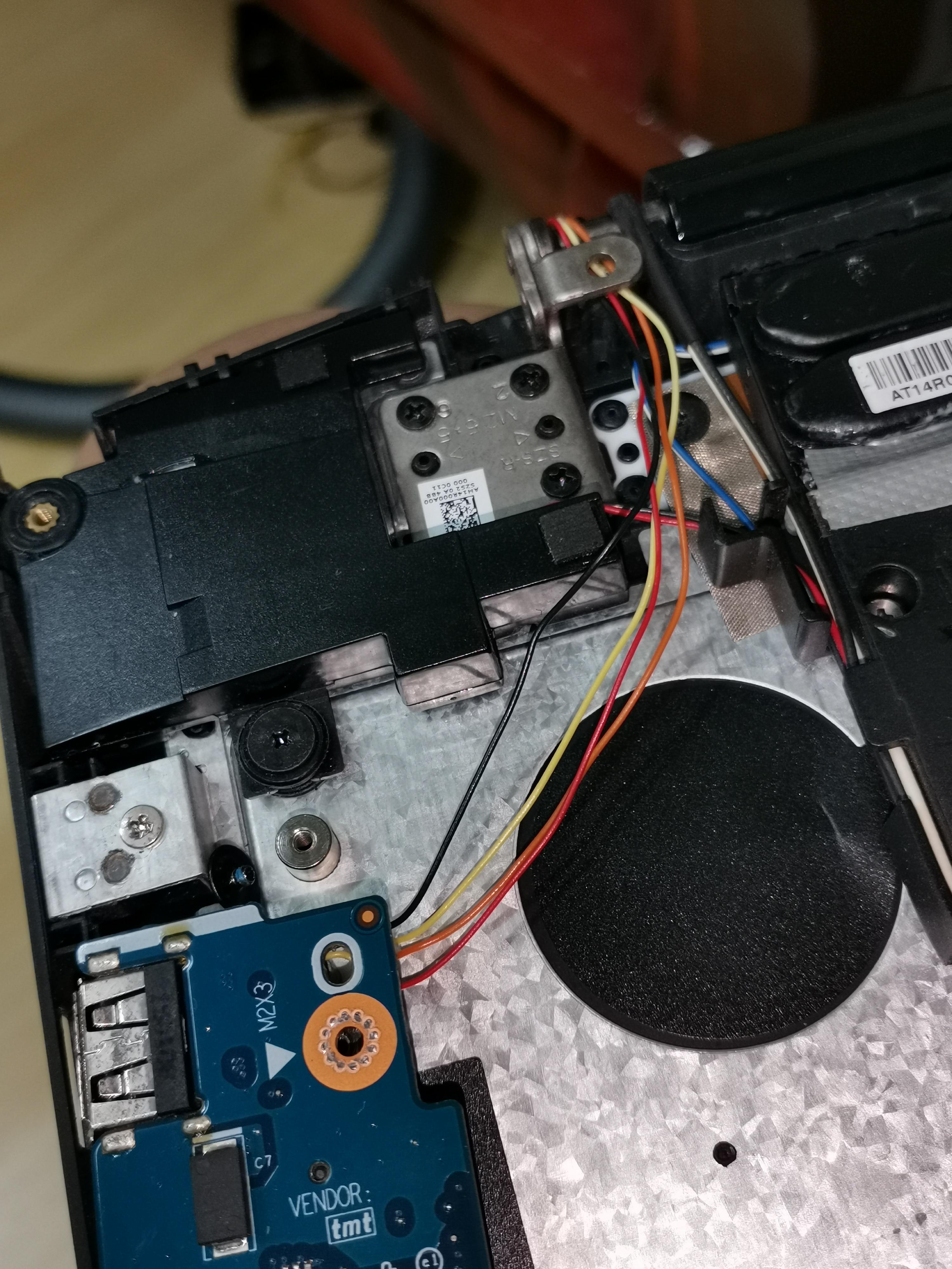
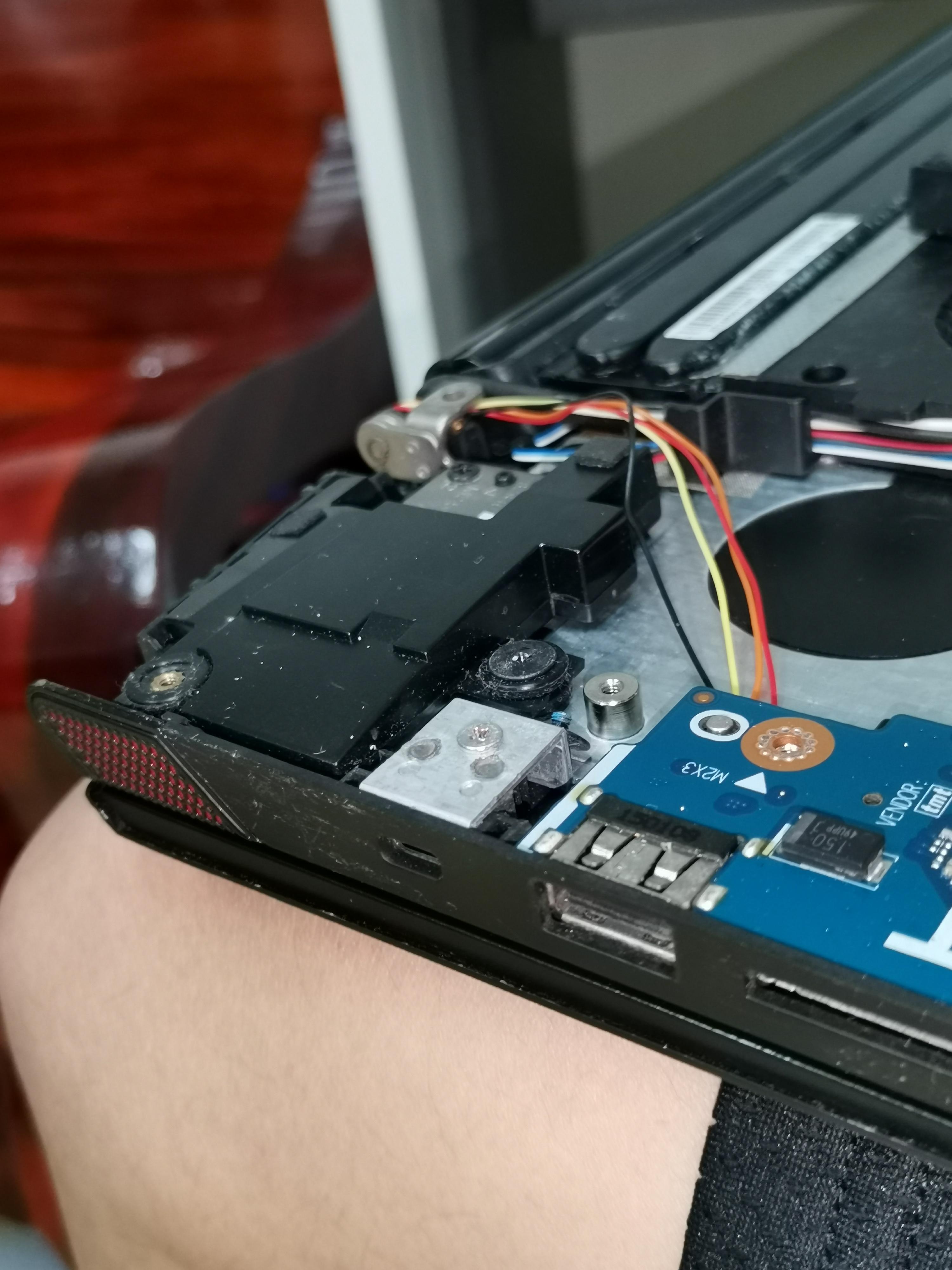
In order to communicate to the laptop, the Arduino board(Atmega32u4) needs to connect to one of the usb ports of the laptop.
Which USB port to use?
The port that is connected to our Arduino will only work for power-only devices like an led light or usb fan. You will gain full usb functionality back when you switch off the popup display.
There are 3 usb ports on my laptop 2 of them are high-speed USB-3.0, so I choose the lowest-speed USB-2.0 because the speed doesn't matter for this project.
Here's how I did it:
- Flip the laptop over.
- Removed all screws.
- Lift up the backplate.
- Disconnect the battery.
- Remove any obstacle to accessing your USB port. (In my case, it is a speaker)
- Solder 4 wires to the back of the USB port.
- Route the wires to the top part of the laptop(same path as the cable of the LCD screen or wifi antenna)
- Flip it back and remove the screen bezel.
- Pull the wires out from the lower part.
- Remove all screws that are holding the LCD then fold the screen down.(This should reveal a bare back cover)
- Drill a small hole on the back cover for the wires to get out.
- Assemble everything back together!
- Solder the USB wires to the Arduino board. (see next step)
Connections

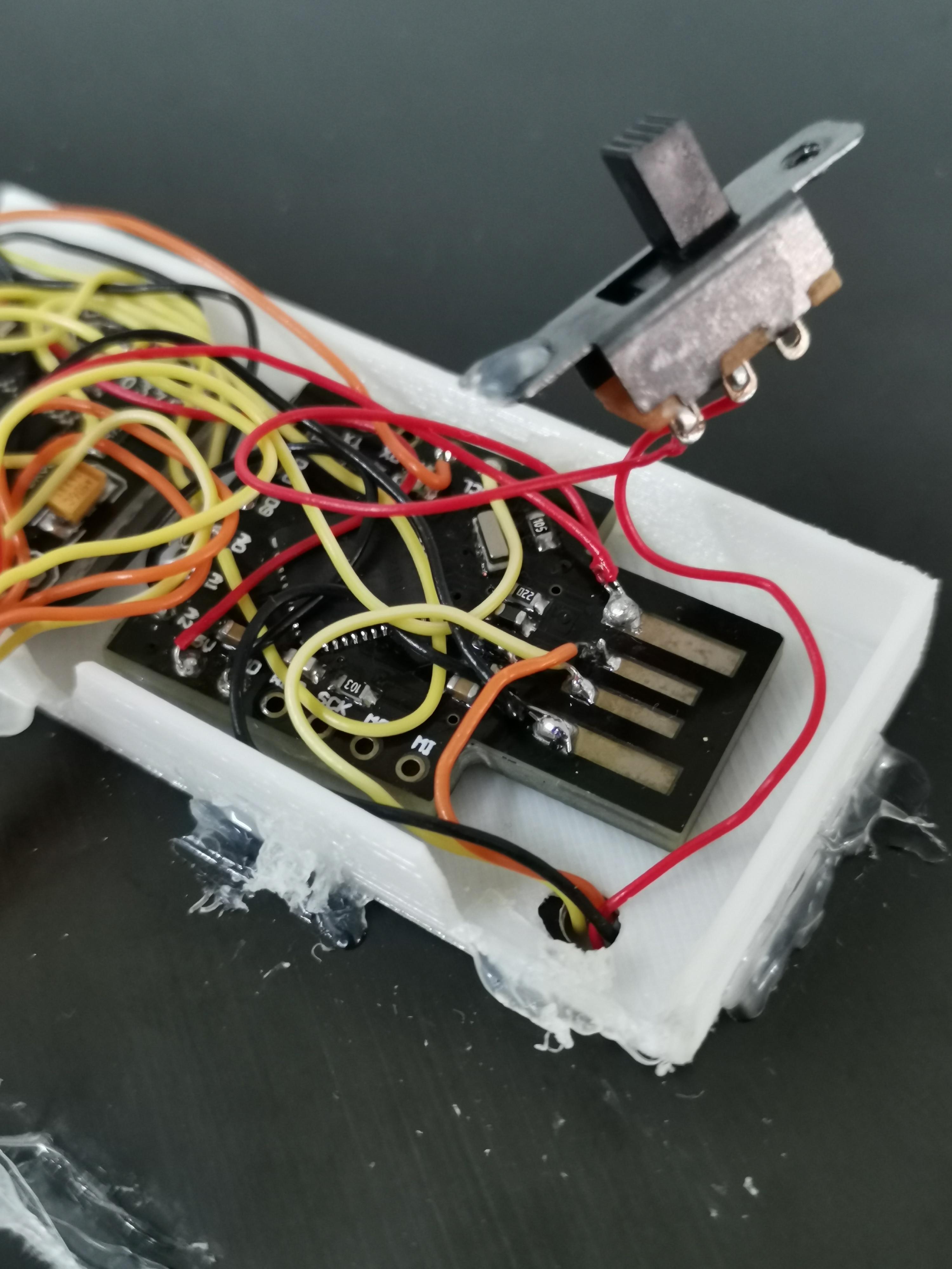
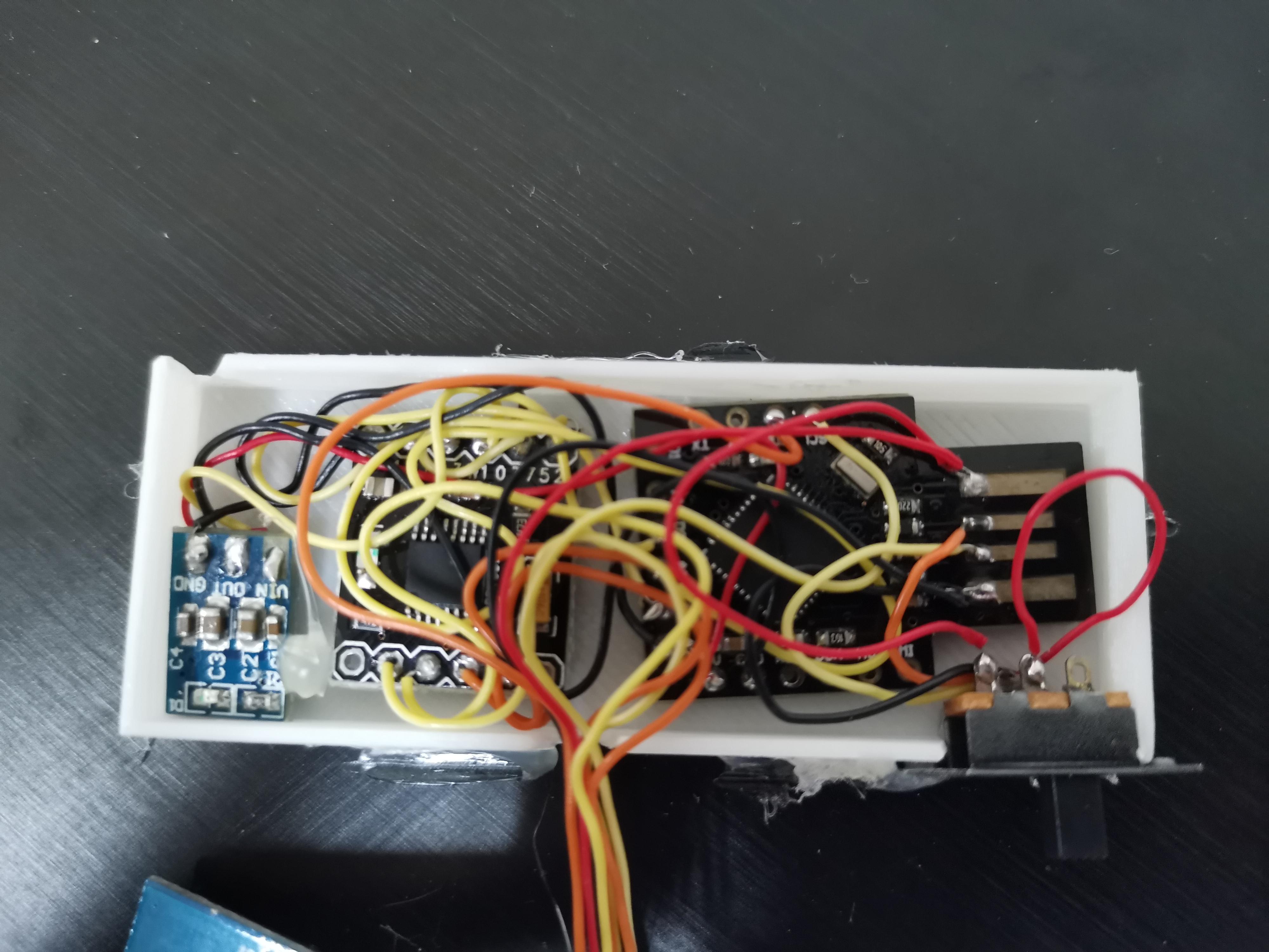
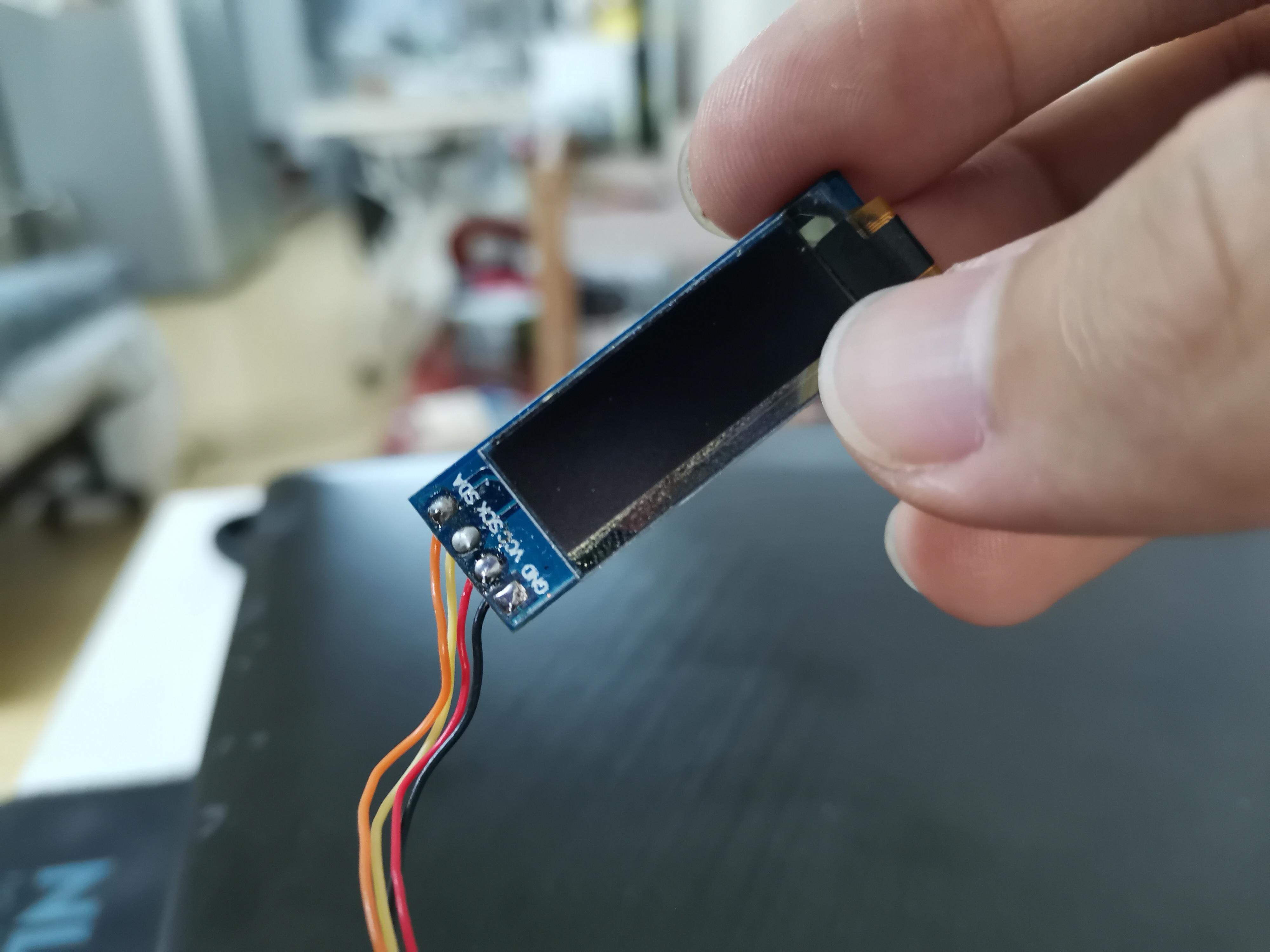
You can connect everything according to the diagram above.
If any module is pre-soldered with header pins you should remove it beforehand.
I use wire-wrapping wire to connect everything, it works flawlessly for this project that has a lot of connections that are small and close together. I can even strip the wires using my nails. I have tried other bigger wires, it is a lot harder to solder.
3d Printing
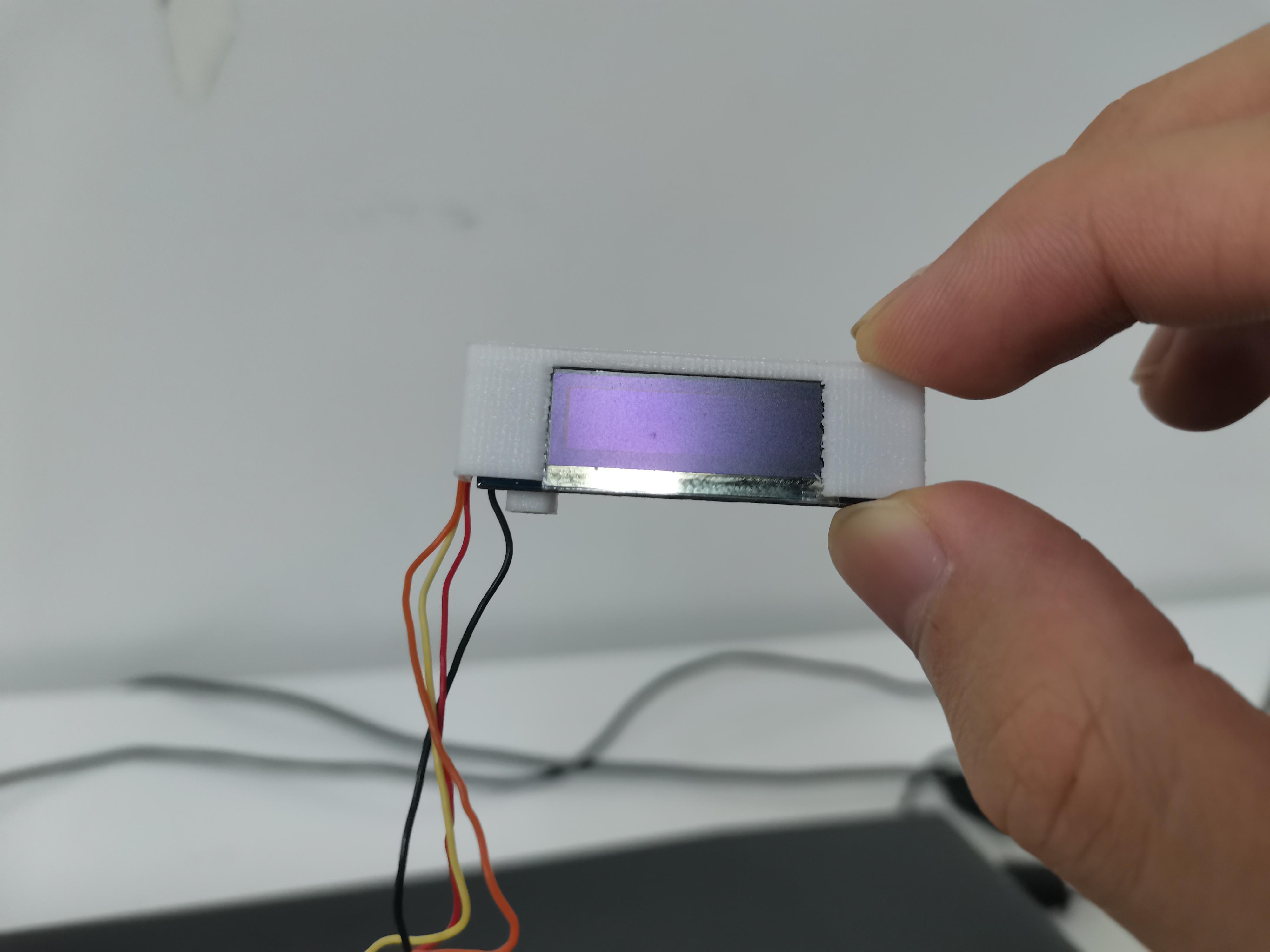
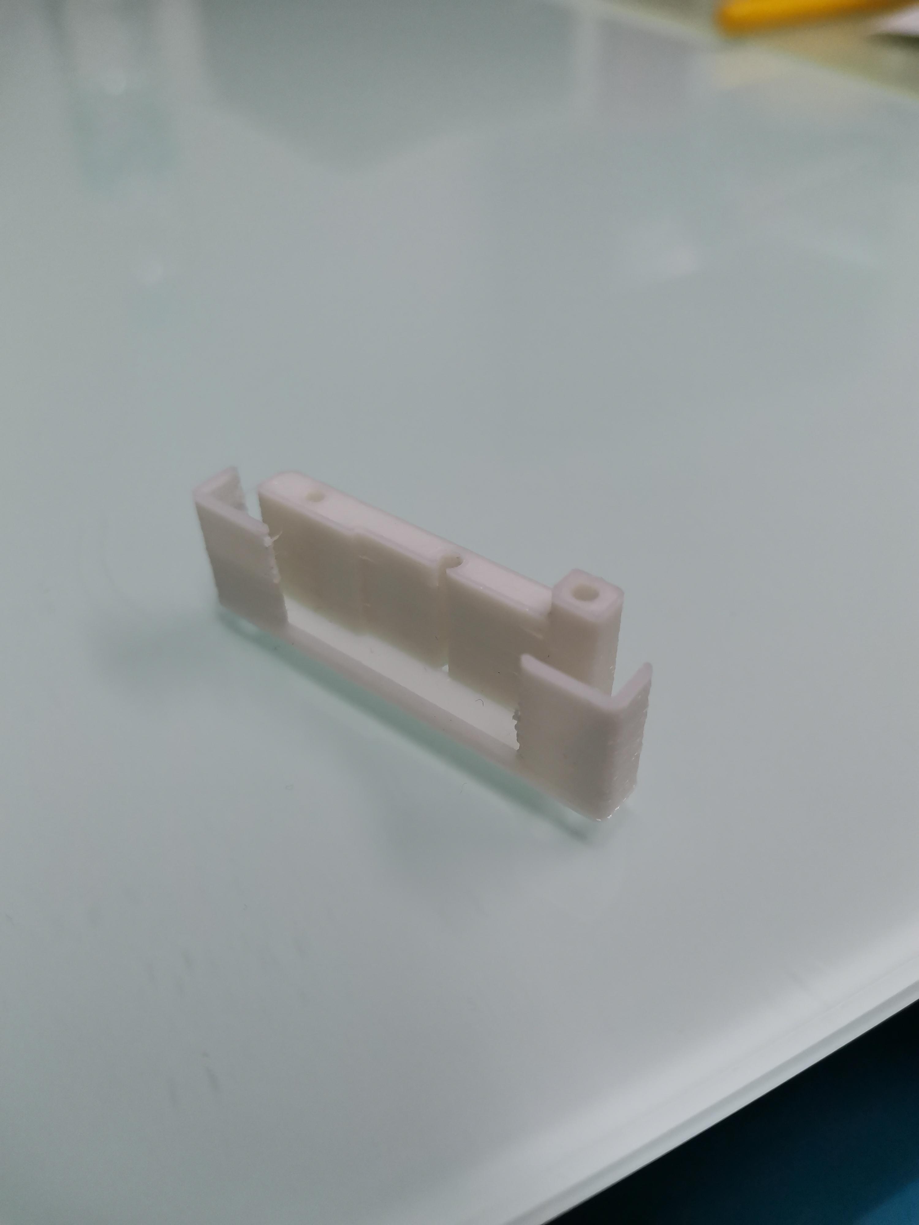
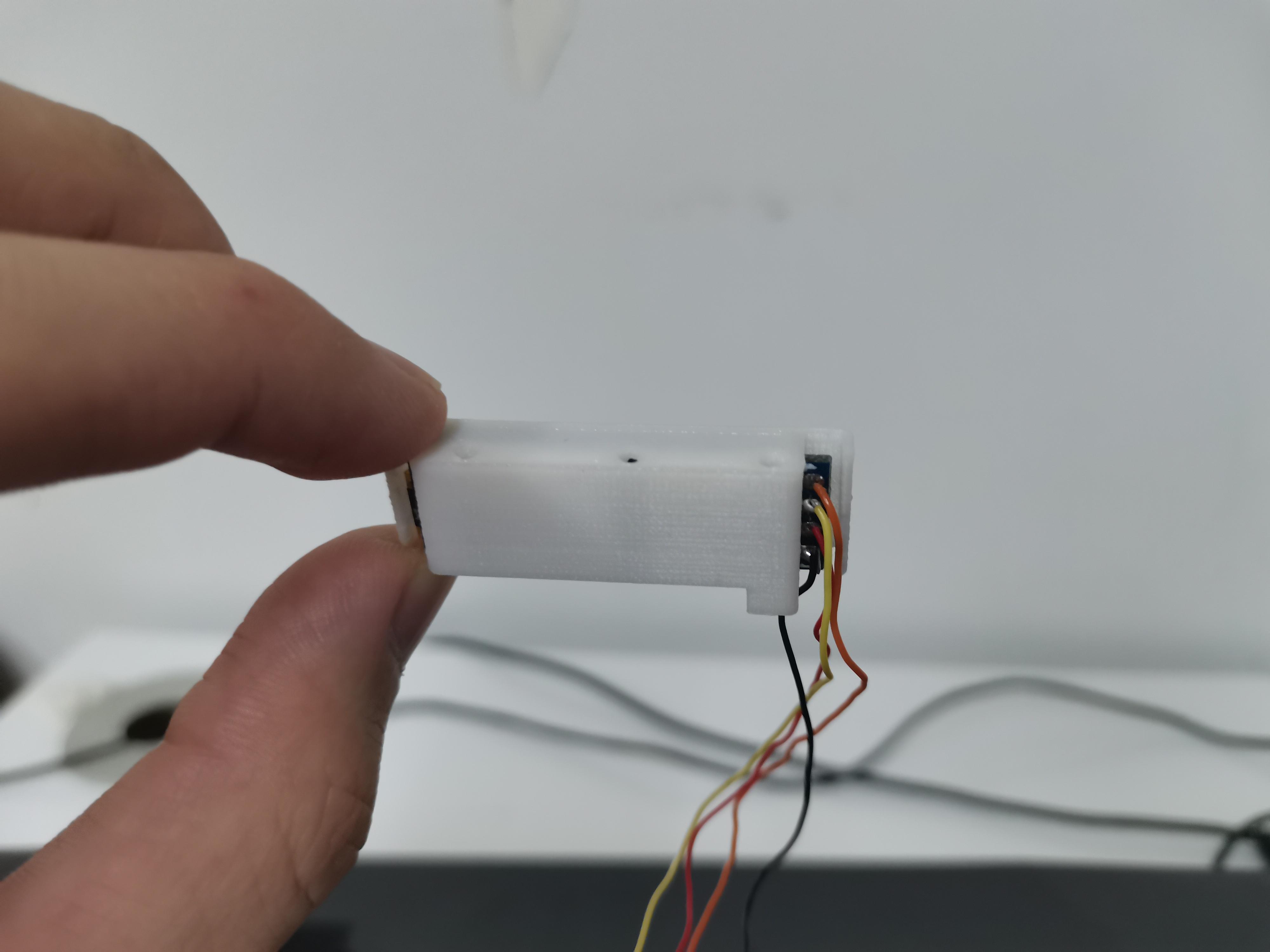
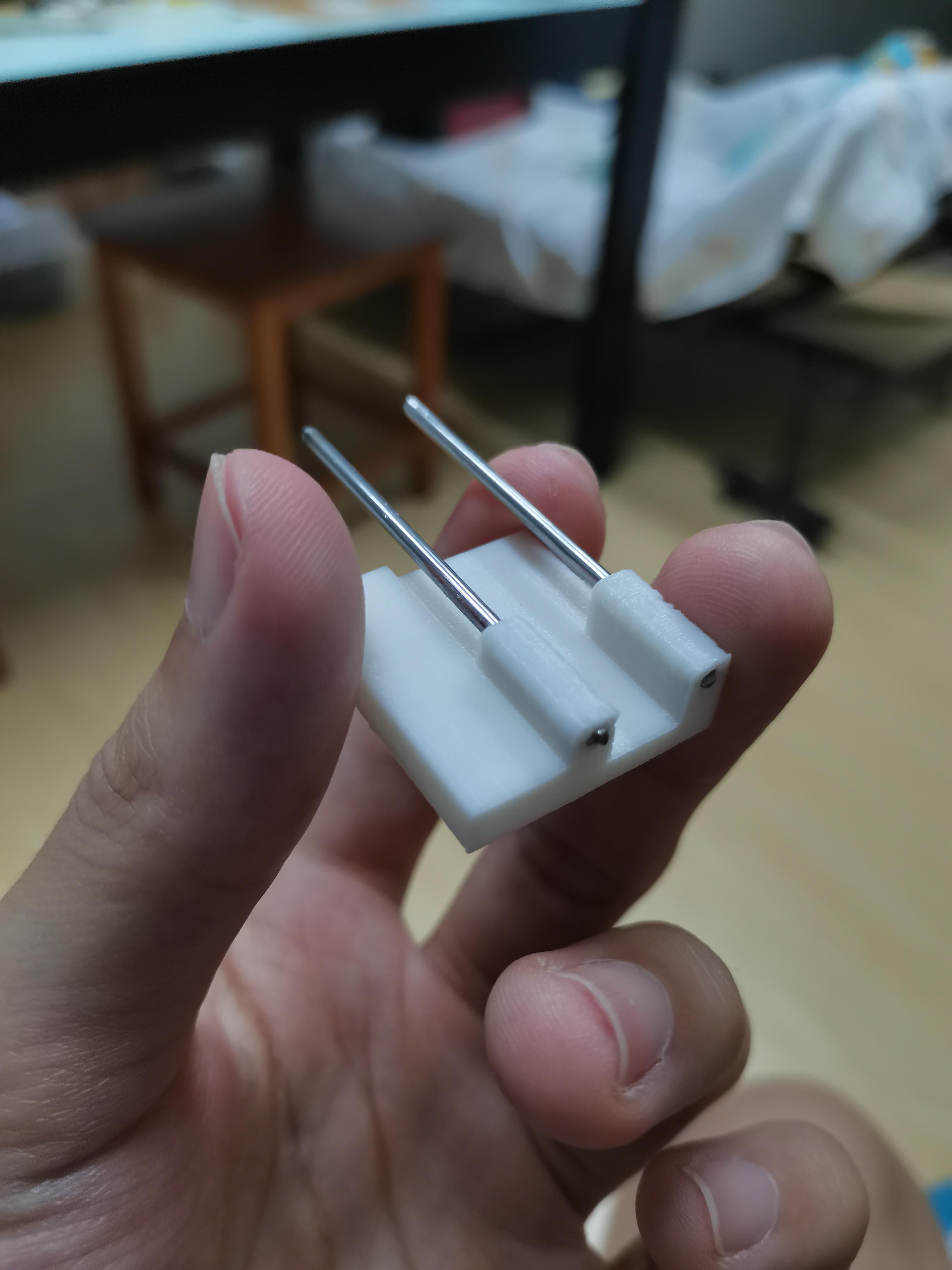
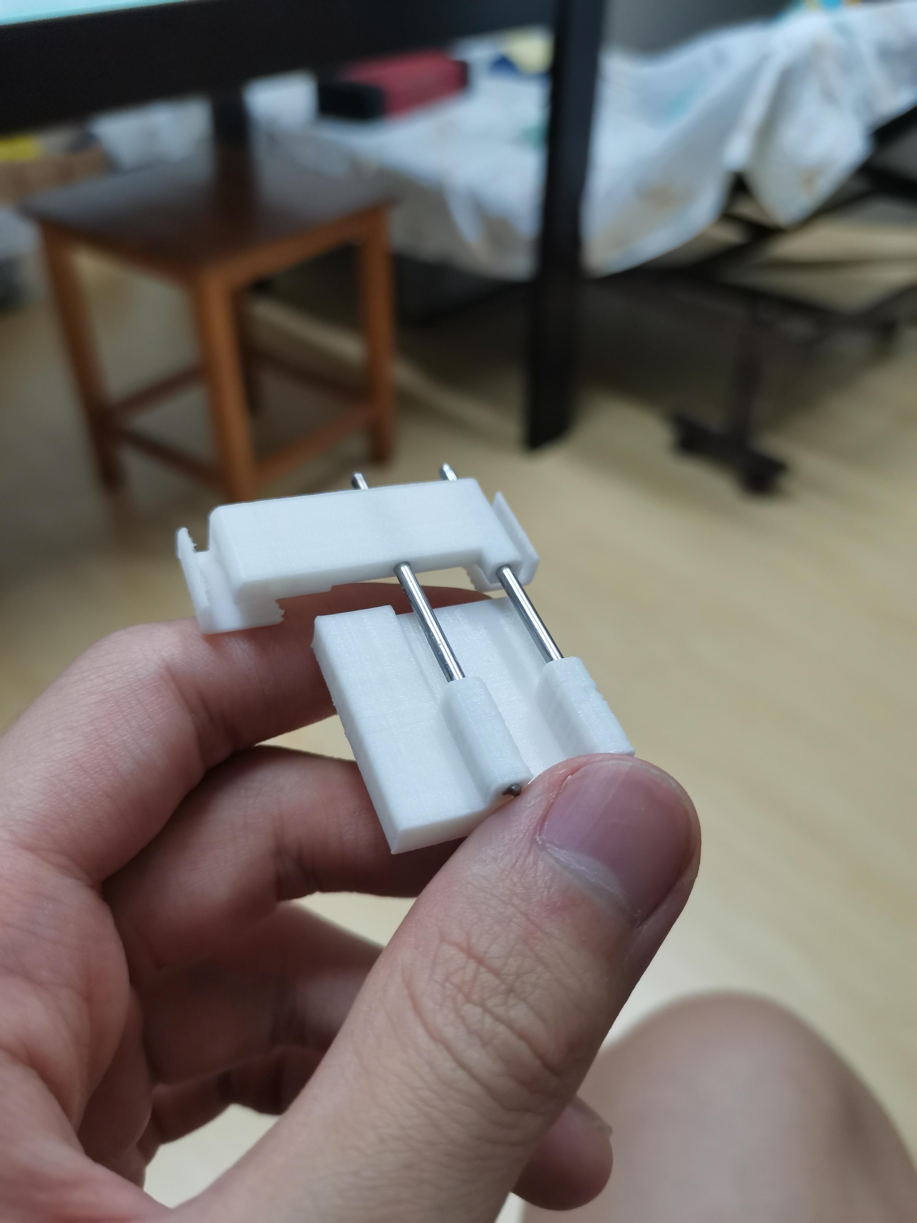
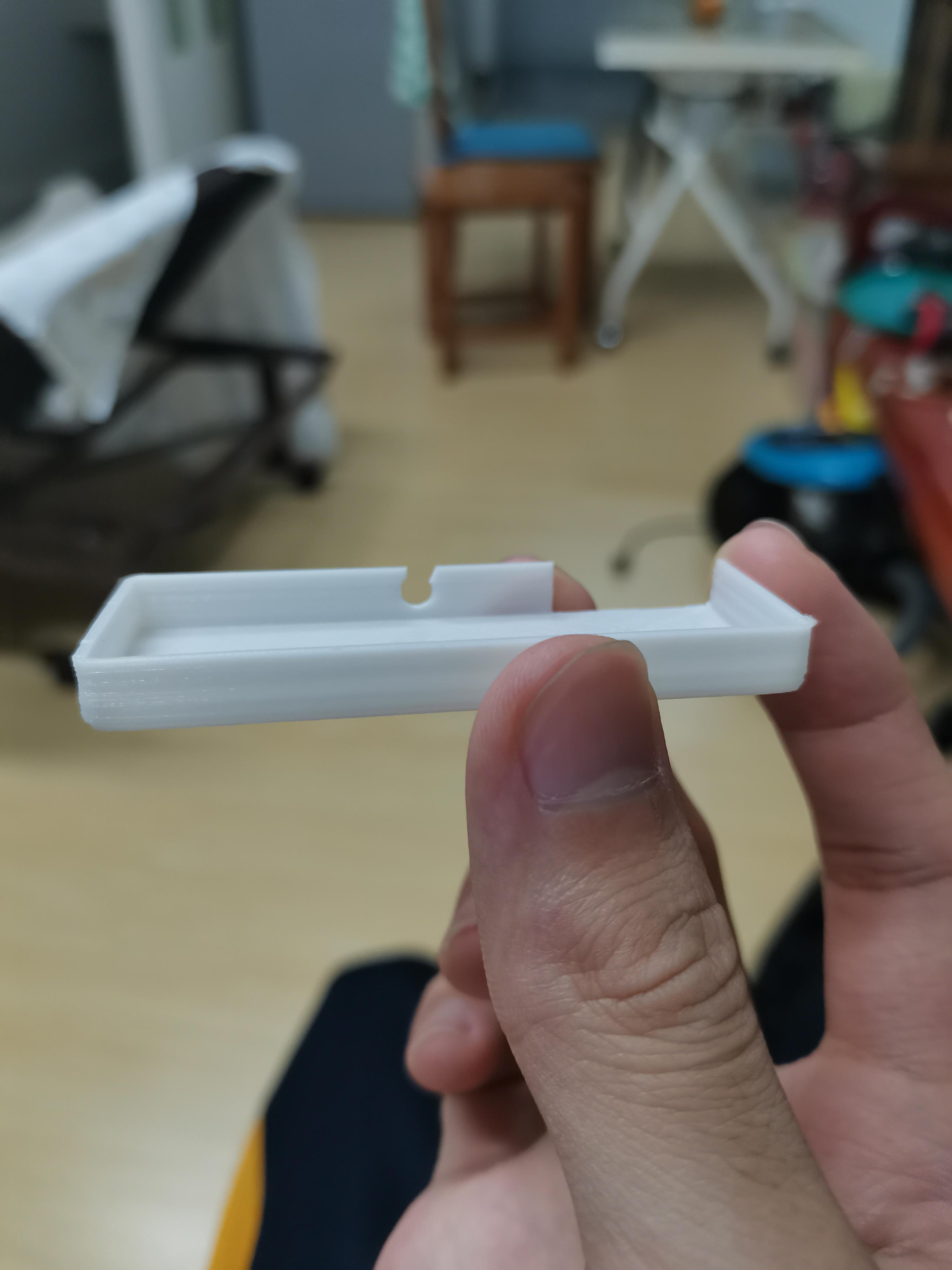
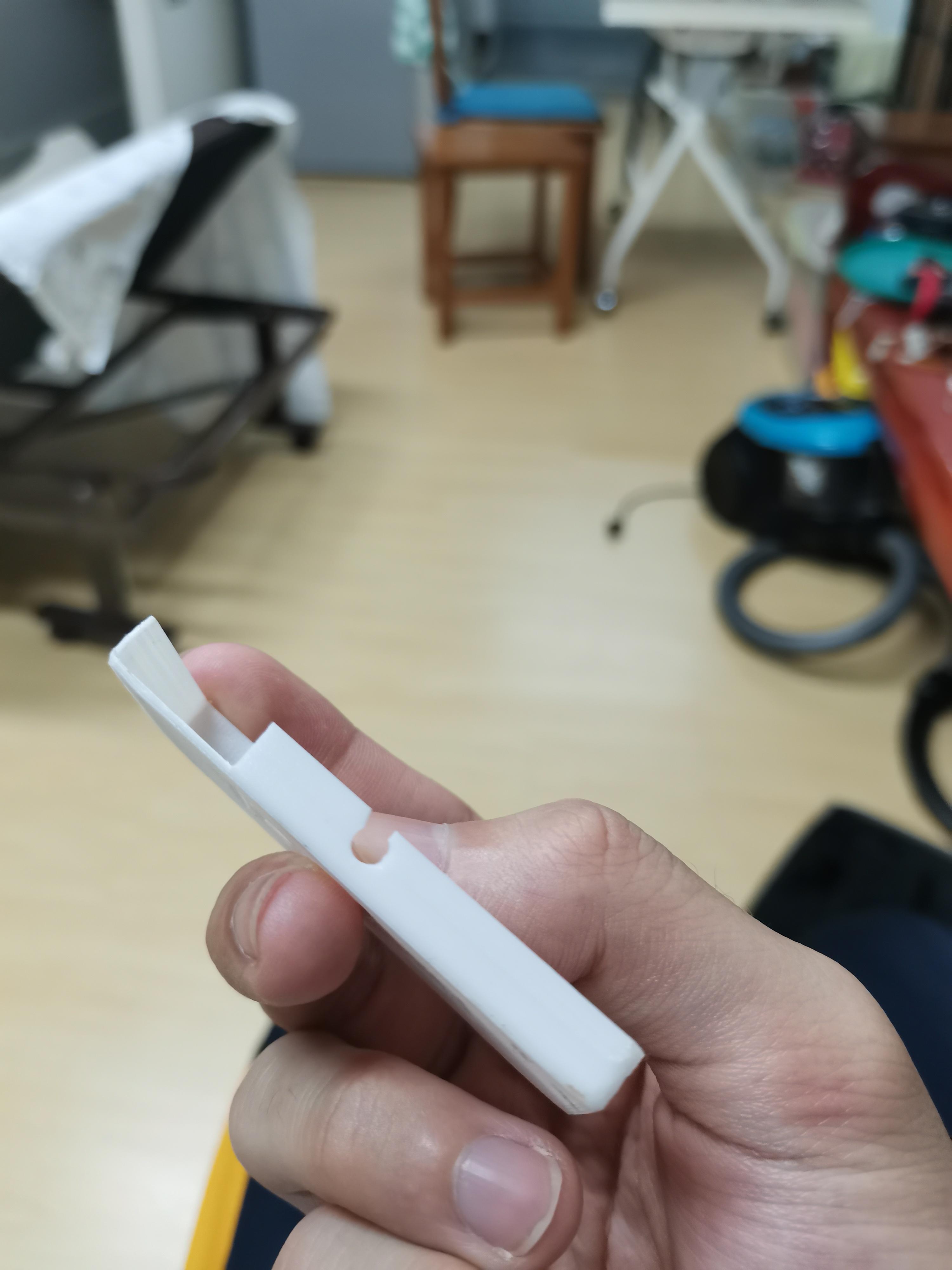
The STL files that I provided may differ a bit from the picture because I improved some of the design.
All parts can be printed without support.
Mine is printed in PLA - 0.2 layer height.
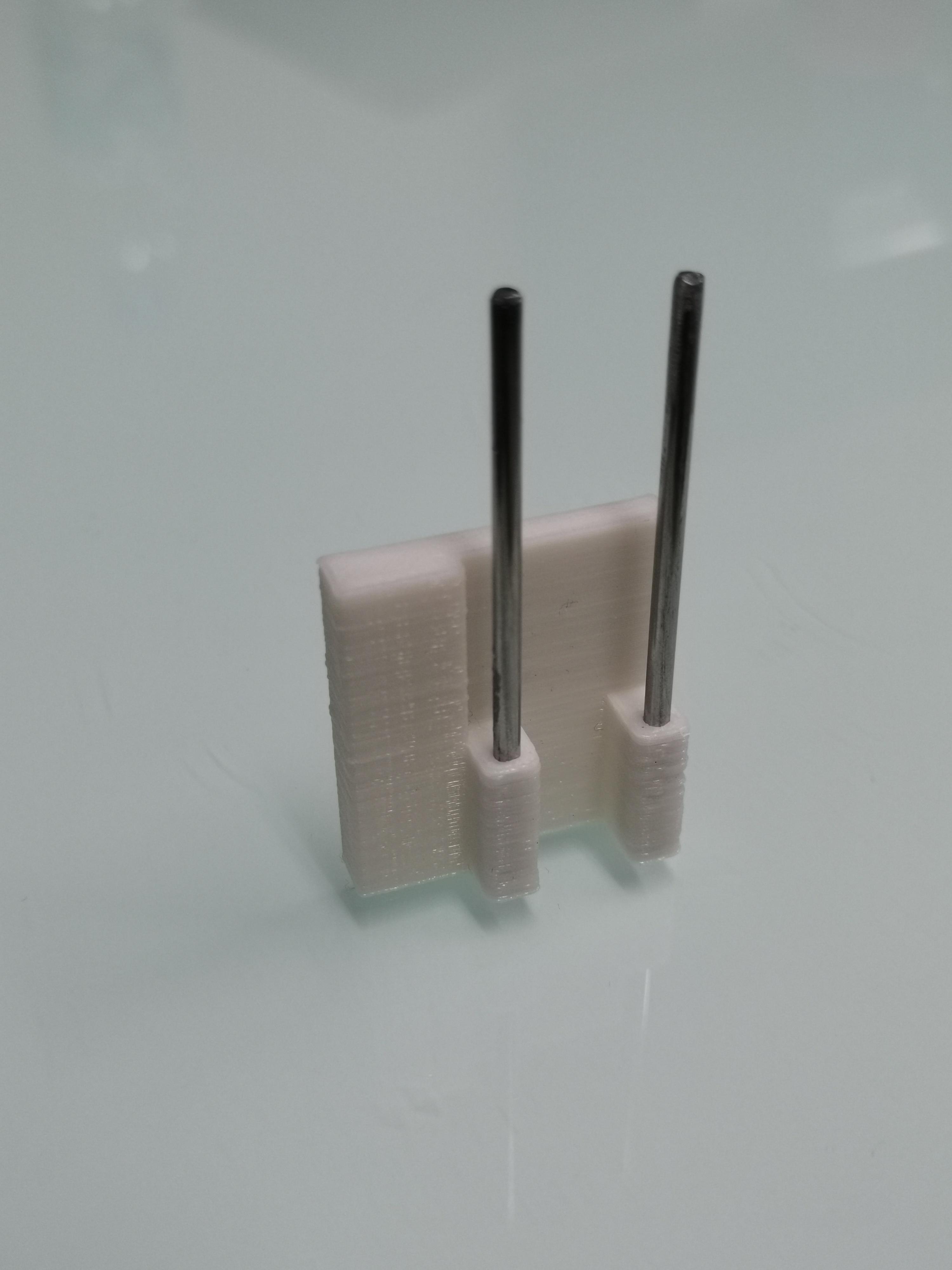
I modeled the holes quite tightly so I need to use a 2mm drill bit to drill the holes before inserting the rod. (The size may vary a bit for your printer)
For the carriage part, I insert the rod into the holes then slide it up and down until it slides smoothly. (The friction will generate heat thus smoothen the surface inside.)
If the holes don't fit for you. There is a very useful setting in Cura slicer that you can use to adjust the size of the holes called "hole horizontal expansion".
The box is printed in two parts, it will be the housing for all the messy electronics, you will need to drill or cut holes for the wires and the on-off-switch. I use a wire-cutting plier. The OLED and the motor will be in a separate part.
Assembly
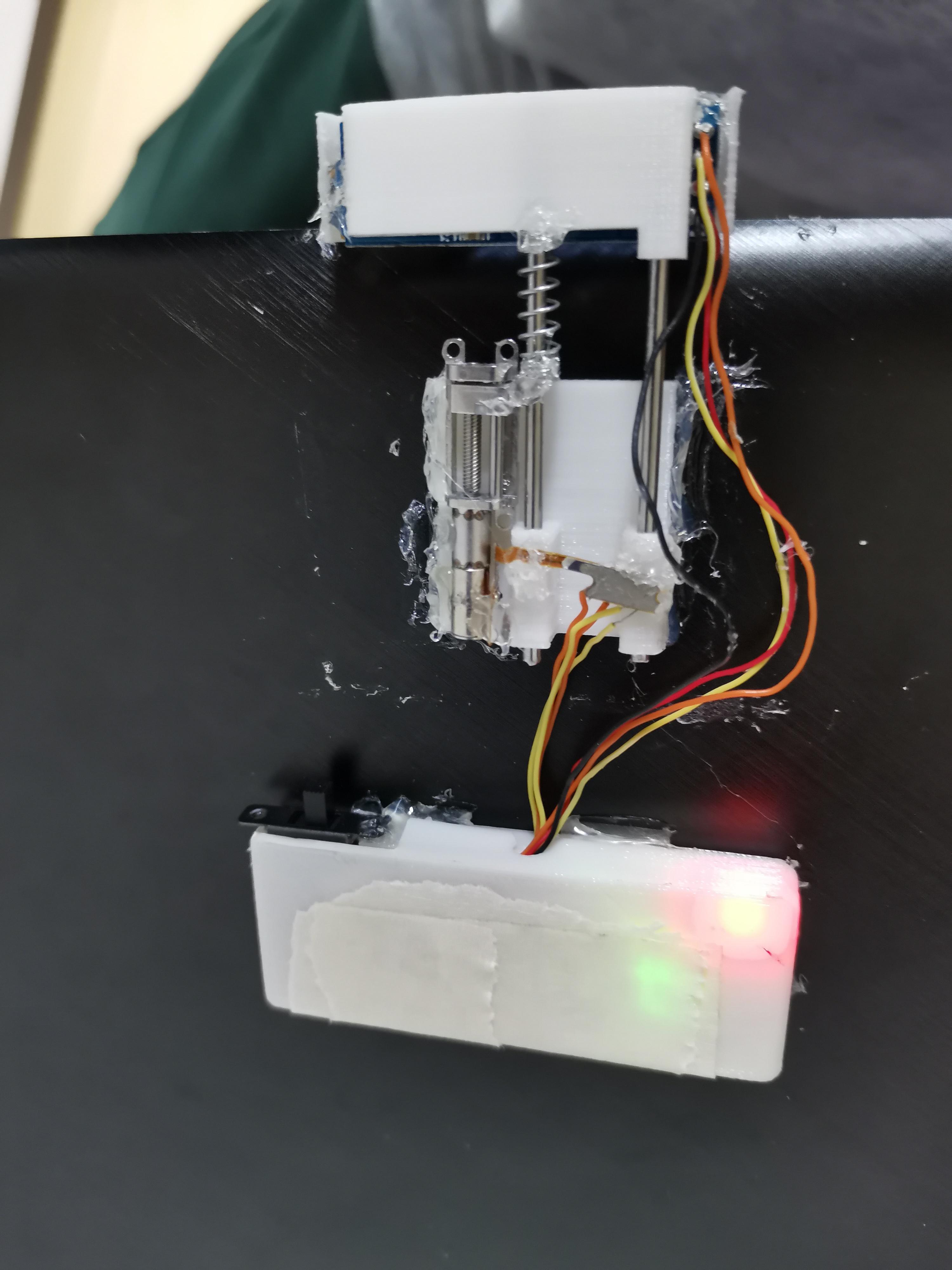
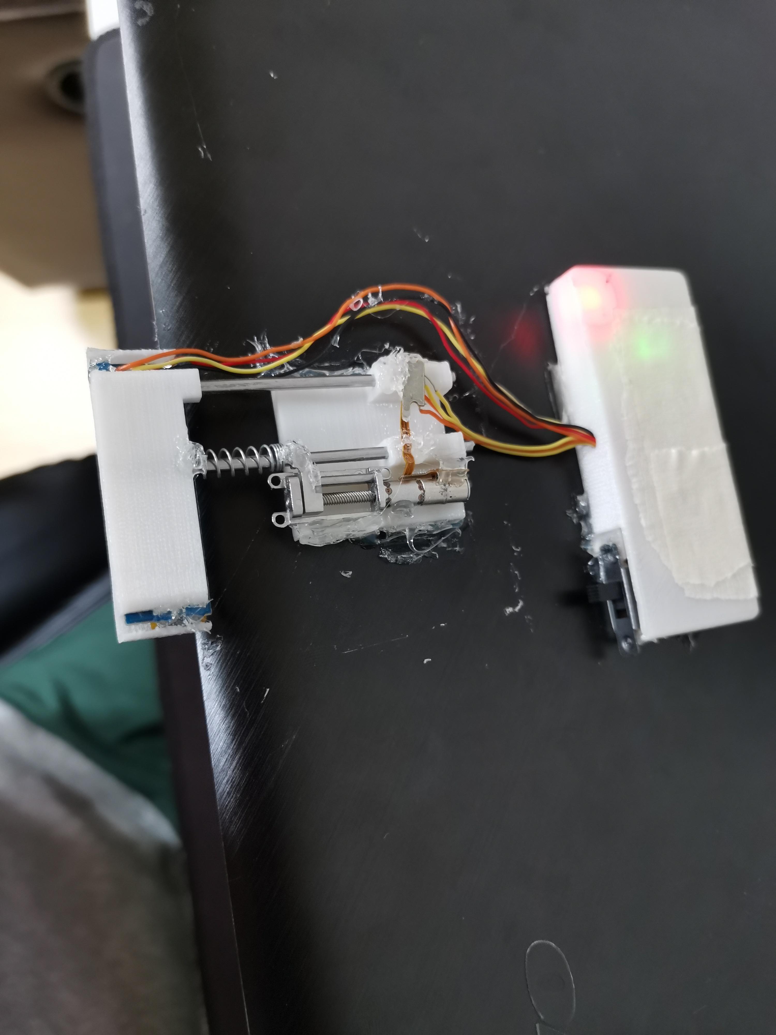
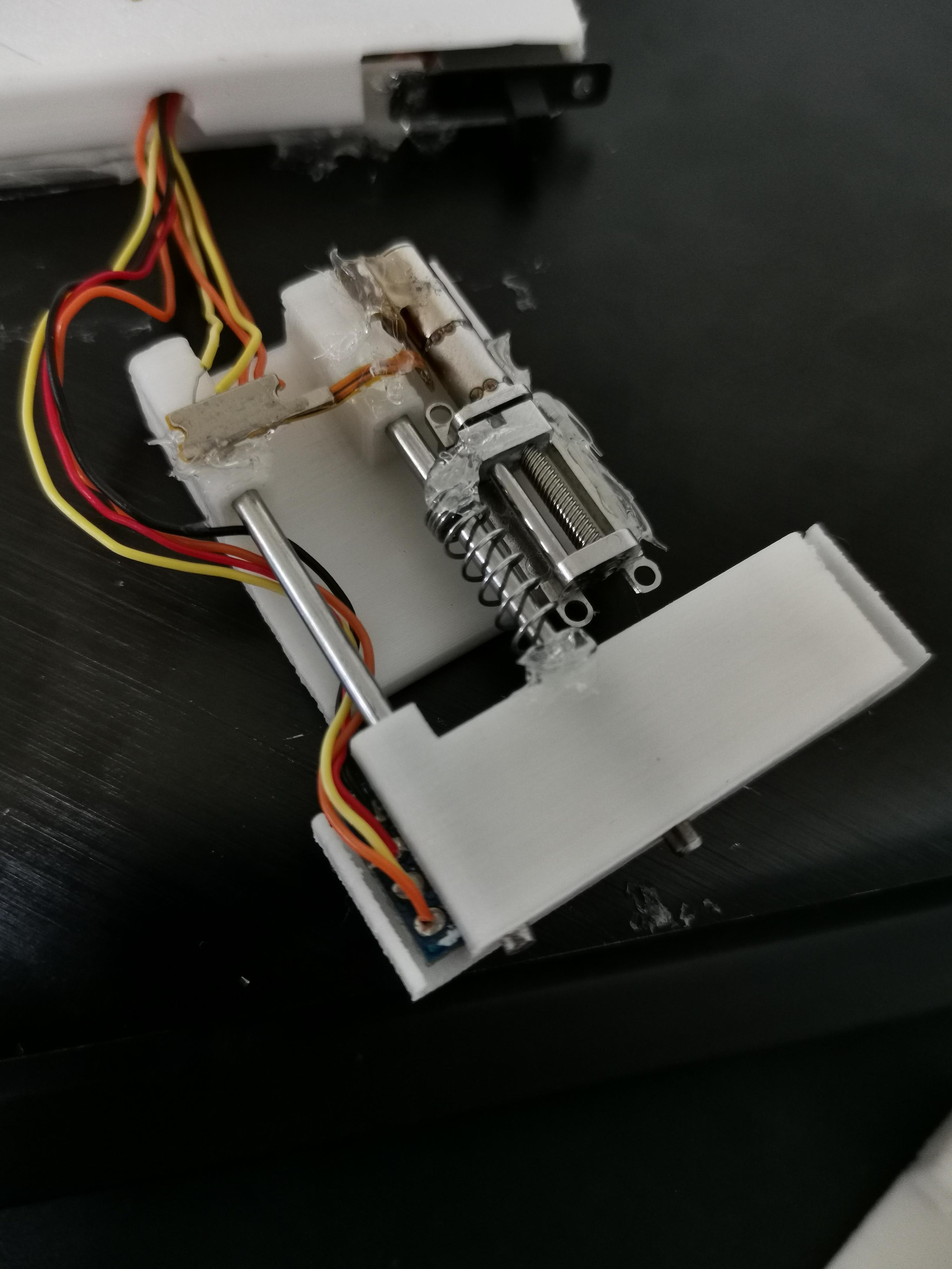
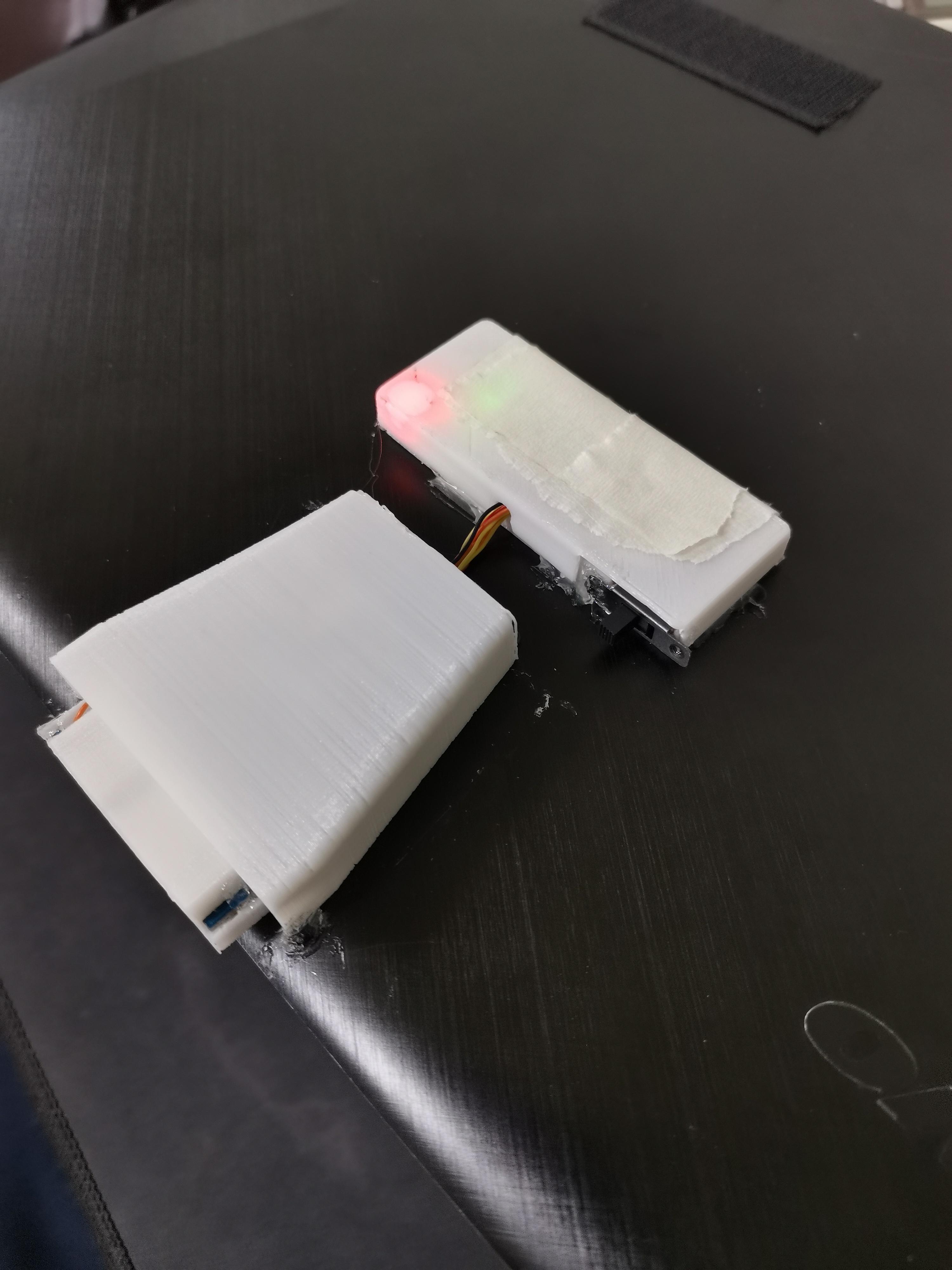
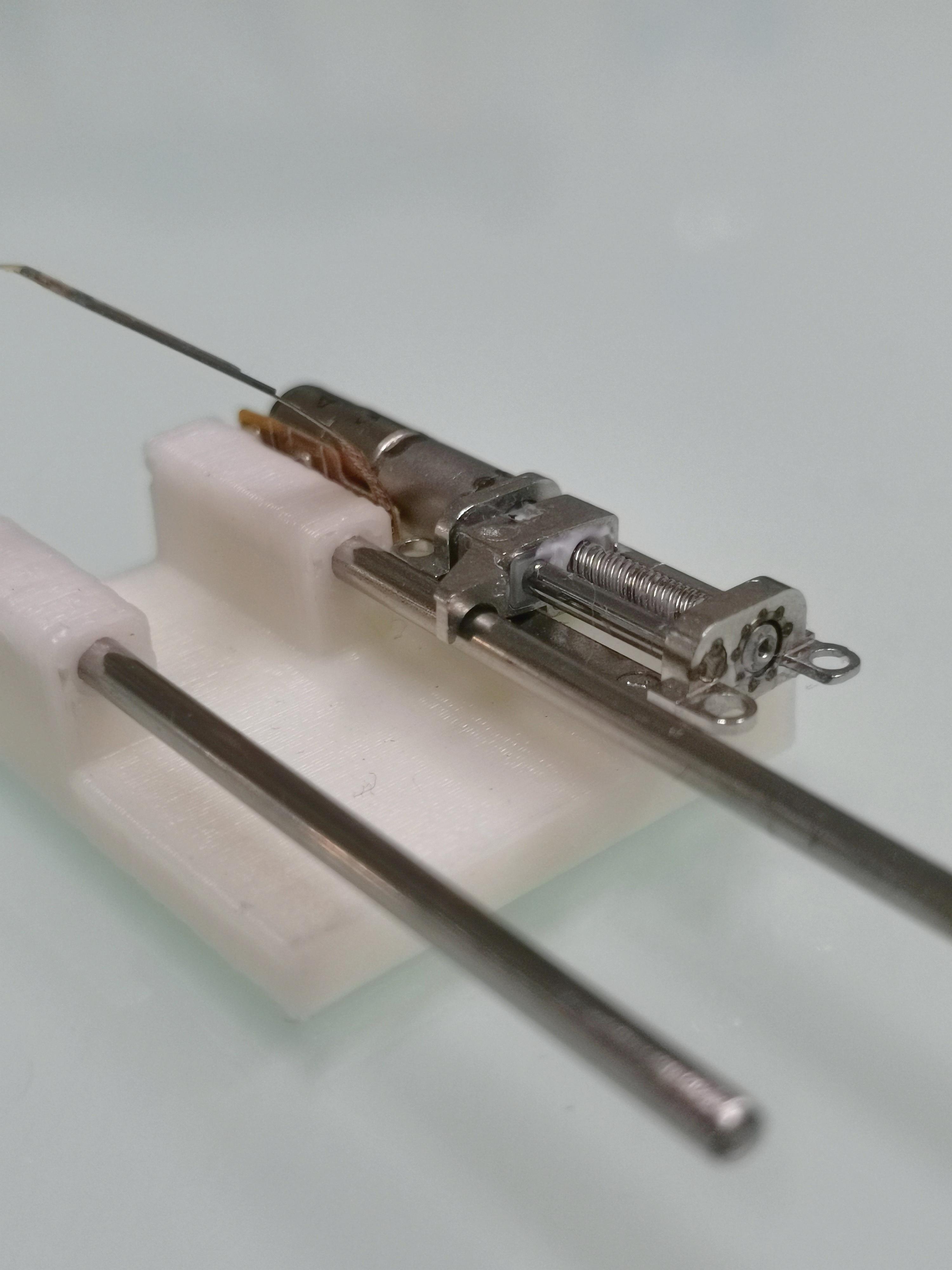
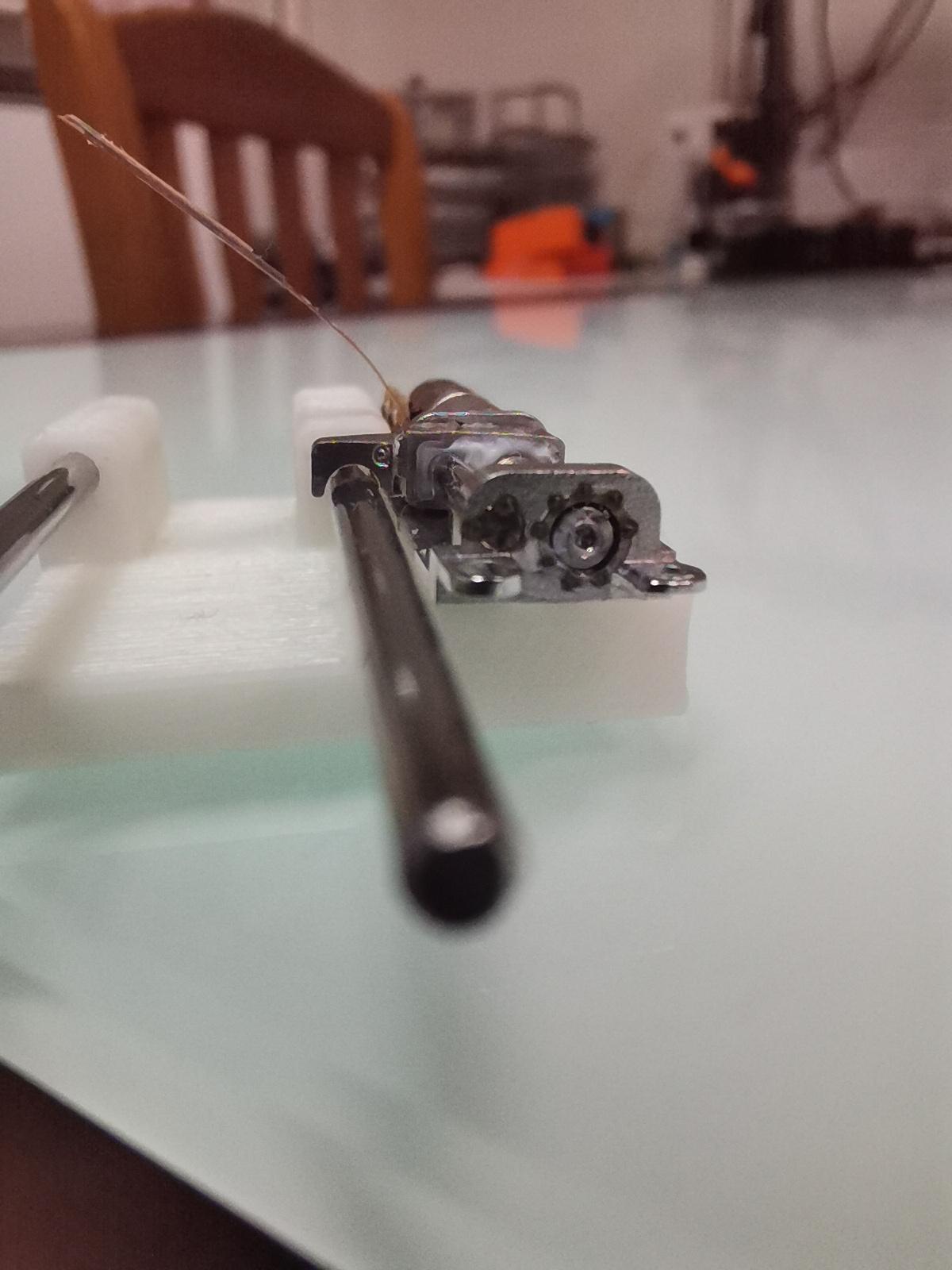
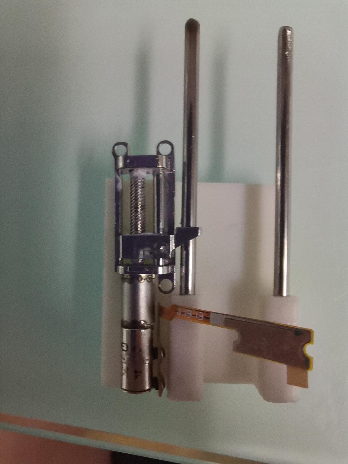
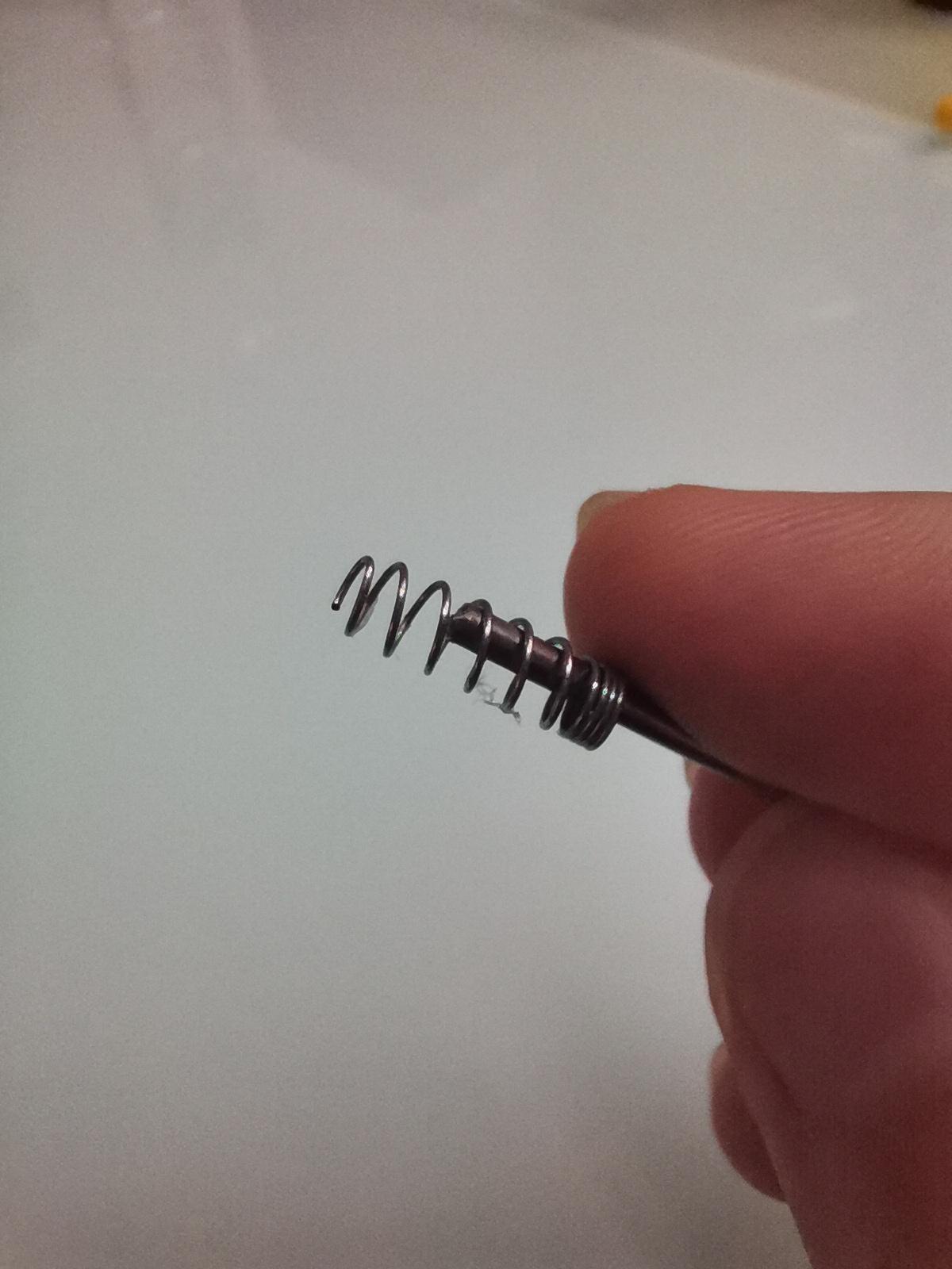
Salvage a spring from a pen. Then cut it to length.
I cut the stainless rod to length.
Attach the rods into the holes of the base part.
Mount the motor in place with a hot glue gun -make sure that the slider of the motor is placed over the rod.
Glue the spring to the slider. Glue another end of the spring to the OLED carriage(case).
The electronics box is placed over the hole. And everything is glued on the laptop.
Arduino Code
When you upload the code to the board select "Arduino Leonardo".
If you want to change the splash screen logo(Adafruit's logo):
I changed my splash to a "disconnected" logo.
Downloads
Desktop Application

I write the code using python.
I use the Psutil library to get CPU performance data. And Pyserial library to communicate with the Arduino board via com port.
Tkinter library to create desktop UI.
I have made an EXE file for you to download and run it on your computer. (Tested on Window10-64bit)
In case .EXE is not working for you, you need to install python and the libraries manually.
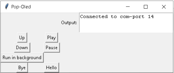
Firstly, you will need to enter the com-port number to which the Arduino is connected to. (it's the same port as when you upload code in Arduino IDE). Then click "connect".
If you enter the com port number correctly, it should now show the live cpu percentage on the OLED, and the control menu should show up.
menu:
Up/Down --> slide up/down 1/6 of the full stroke length.
Play-->display the real-time cpu percentage.
Pause-->pause
Hello-->slide up 100%
Bye-->slide down 100%