LIllI the Humanoid Robot for ROS2 and AI Experiments by Personal Robotics
by PersonalRobotics in Circuits > Robots
487 Views, 2 Favorites, 0 Comments
LIllI the Humanoid Robot for ROS2 and AI Experiments by Personal Robotics

About lIllI
lIllI is a humanoid robot made from laser cut wood. She is a developing platform for programmers who need a robot to experiment with on on small budget. lIllI is constructed with simplicity and availability in mind, and thus uses standardized parts that should be available in most regions.
IllII started as a 3D printed project. However, after a while I switched to laser cutting for several reasons. I wanted the production process to be swift and reproducable and I also tried to keep it as sustainable as possible.
The templates can be cut from any 4mm material, and I chose wood as it ticks the following boxes:
Cheap
Easy to get
Easy to work with
Environmentally friendly
Tough
Looks really cool!
It uses 25 standard servo motors, and the motors can be controlled by your micro-controller or computer of choice. I prefer using a Raspberry Pi or Arduino, as it is also cheap and available, however, you can use your platform of choice. Her head also fits an Nvidia Jetson. To control this amount of motors, you will need a lot of PWM (Pulse Width Modulation) pins. We found that using two of the PCA9685 chips over i2c is a simple solution for this.
Links:
Official Website: Personal Robotics
lIllI is based on Halley the ambassador robot, by John Choi. Unfortunately, John has moved on and no longer develops Halley.
However, I am working on a ROS2 system for her, which can be found on the Personal Robotics github site.
It is size compatible with Poppy and Aster.
It can also use the myrobotlab software designed for the InMoov project using the configuration files from our Github.
If you don't have a laser cutter or the time you can buy the kit from my Tindie shop.

Supplies

Get the files here: https://www.thingiverse.com/thing:6945461
or get the kit from here: https://www.tindie.com/stores/personalrobotics/
Before you start building, you should check that you have everything you need.
- One lIllI wooden kit
- Futaba style servo motors (the RC car style) with screws and grommets x 21
- 9G Servo motors x4 (The small ones)
- M3 Bolts x30
- M3 Safety Nuts x30
- M3 Regular Nuts x14
- Servo extension cables
- PCA9685 Servo controller x2
- Computer and micro-controller (e.g. Raspberry Pi or Arduino)
- Power supply for the servos
- Power supply for the Electronics (should be separate)
- Dupont style connection cables as required
Tools:
- Hammer and/or rubber mallet
- Screwdriver fitting the screws you chose
- Needle nose pliers and regular pliers
- Stanley knife
- Sandpaper (optional)
- Servo tester (optional)
Location:
You will need a lot of space. Preferably a large table or bench. Keep your parts organized and finish one body part at the time.
It is also recommended that you mount lIllI somehow, so she does not fall over. This can be done by hanging her from above or by screwing her back to a scaffold through the chest hole.
Do use the rubber grommets and the brass tubes that go in the servo screw holes. That makes the servos fit better and the connection more stable.
Time: Assembling lIllI takes a lot of time, even if you are experienced. See that you have time and resources to finish the build in one go. You need a weekend at least.
Tip: If you want to paint or oil the robot, do it before you take the wood apart. When the wood is connected to the plywood sheets, you can sand and spray it all in one go.
For the latest version of both the hardware and the software, visit my github repository.
Planning (do Not Skip!)

!!Do not break the parts off the boards before you start building!!
If you got the wooden parts from the Personal Robotics shop, the parts on the boards are sorted by body part. If you detach them, you will have a hard time finding the right pieces.
Note: lIllI is improved constantly. Thus, your parts might differ slightly from the illustrations given. Don not panic! Use your imagination and find a solution.
All the limbs are attached to the Torso. Thus it makes sense to start with this. The head usually contains your electronics and should be assembled last.
The recommended progression is a s follows:
- Torso
- Hips (Do left and right simultaneously, as they are mirrored to each other)
- Shoulders
- Legs
- Arms
- Head
- Motor Adjustment
- Cabling
Knolling: Knolling is the act of laying out everything you need for the build. This is good practice when building something. Do this for every part separately and remove the parts that you don't need! This will reduce the confusion that you might feel when starting.
Scaffolding: When the legs are attached, you can mount lIllI in a standing position. This simplifies the attachment of the rest and reduces the risk of breaking something.
Plywood might fray at the edges if you are not careful enough. However, most of the time this is not a problem. Due to wood's organic properties, this does not show in the final build. Just sand it and make the slots clean. Use wood glue if you break something.
Having a selection of small wooden boards can be beneficial as an underlay when punching the parts together. This might save your table from becoming bumpy, and sometimes the parts are not flat and the underlying surface needs to be elevated.
About The Servos:
lIllI uses standard servo motors. The kind that is made for radio controlled models. They can be bought really cheaply and have a standardized form factor. However, it should be noted that their quality can vary greatly. Some are slow, some fast. Some are cheap and some can be very expensive. You can even get very powerful ones, but remember that these draw more power. A lot more.
Since the servo motors are not really made for robotics, chances are, you will break a few. Getting a few spare ones is therefore recommended.
Remember:
Always use a separate power supply for the servos! Do not power them from the GPIO pins as they do not support the current draw.
The micro controller and the servos need to share a common ground. If they shake and jitter, your ground is not shared.
It is recomended to finish the build before you screw the servo horns to the wood. That way, the servos can turn freely when you center them.
Torso


Assembling the torso is pretty straight forward.
Use pliers to gently crack the wooden boards apart. The pieces are held in place by tiny bridges that can be broken by bending the wood. Be patient!
When the parts are free, use a Stanley knife and some sandpaper to remove any off-standing fibers.
Use a hammer or rubber mallet to punch the parts together as shown on the images. Most parts are made in a way that makes it impossible to use them in a wrong way, but no system is fool proof. So be sure that you read the whole thing and understand it before you start.
Shoulders


The shoulders are also straight forward. They are Just make sure you align the slots correctly.
Arm


Make one first, and use it as a template to make sure that you have a mirrored pair!
Hips


The Hips are slightly more complicated. They have a lot of small parts that can easily get damaged. Be sure to understand the construction before you begin and be sure to build two mirrored hips.
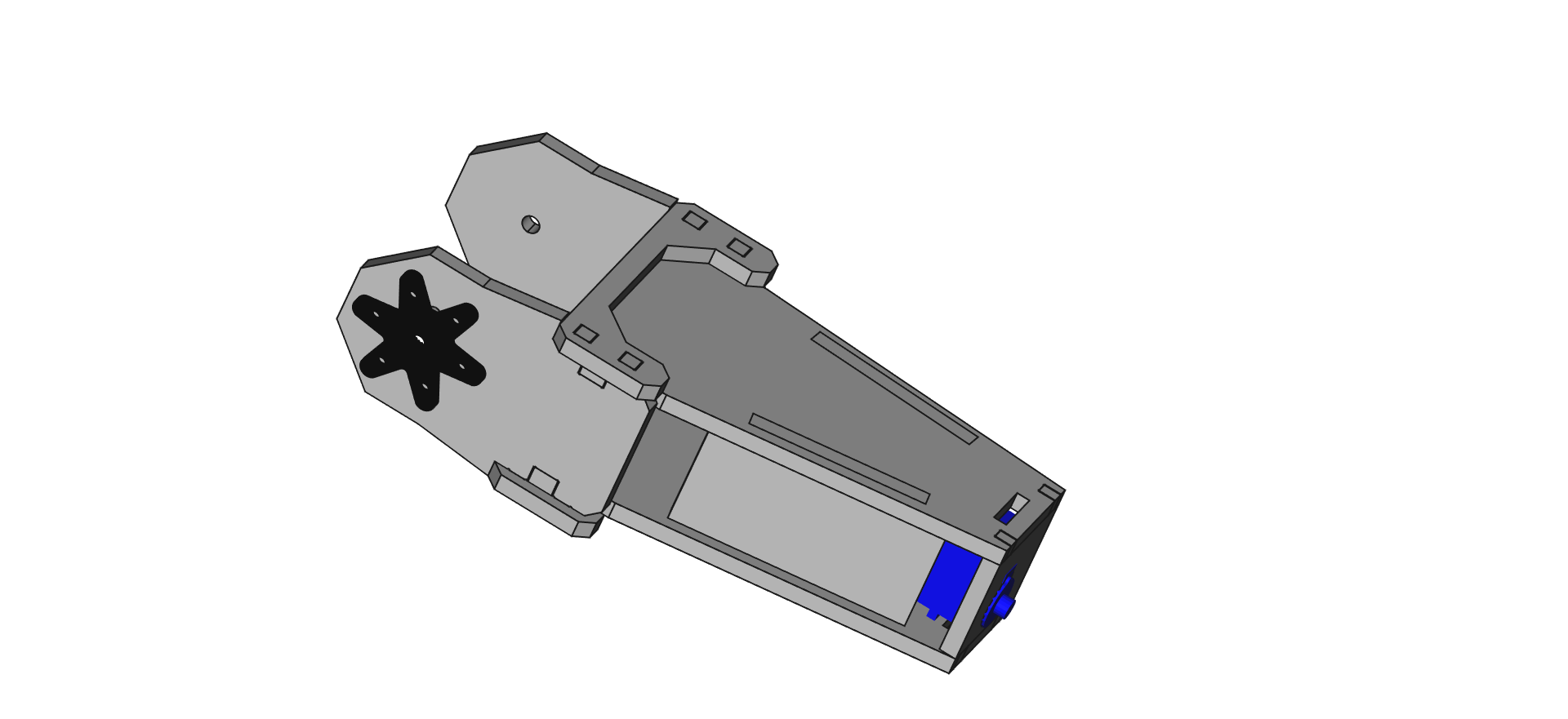
Leg


There is not much to say about the construction of the legs except to make sure that you have a mirrored pair!
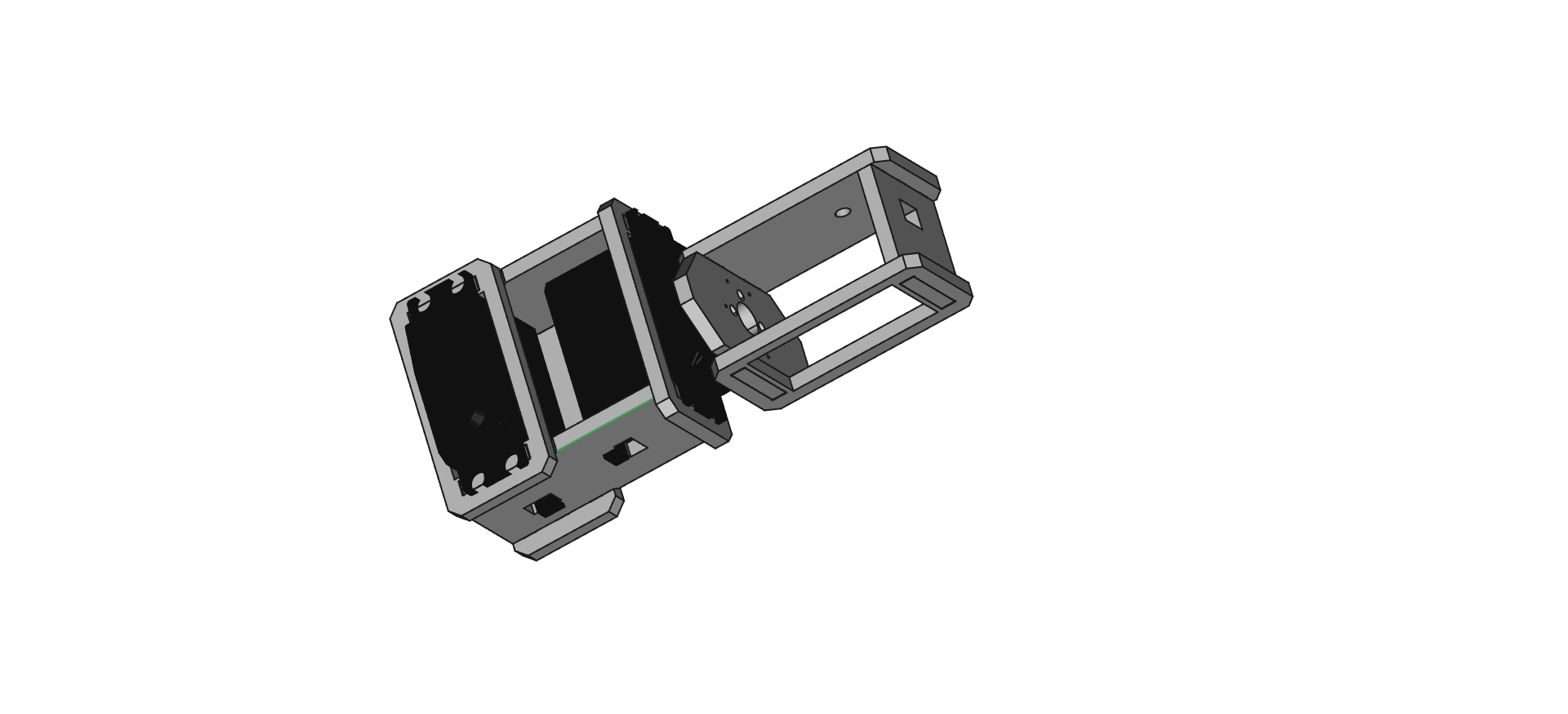
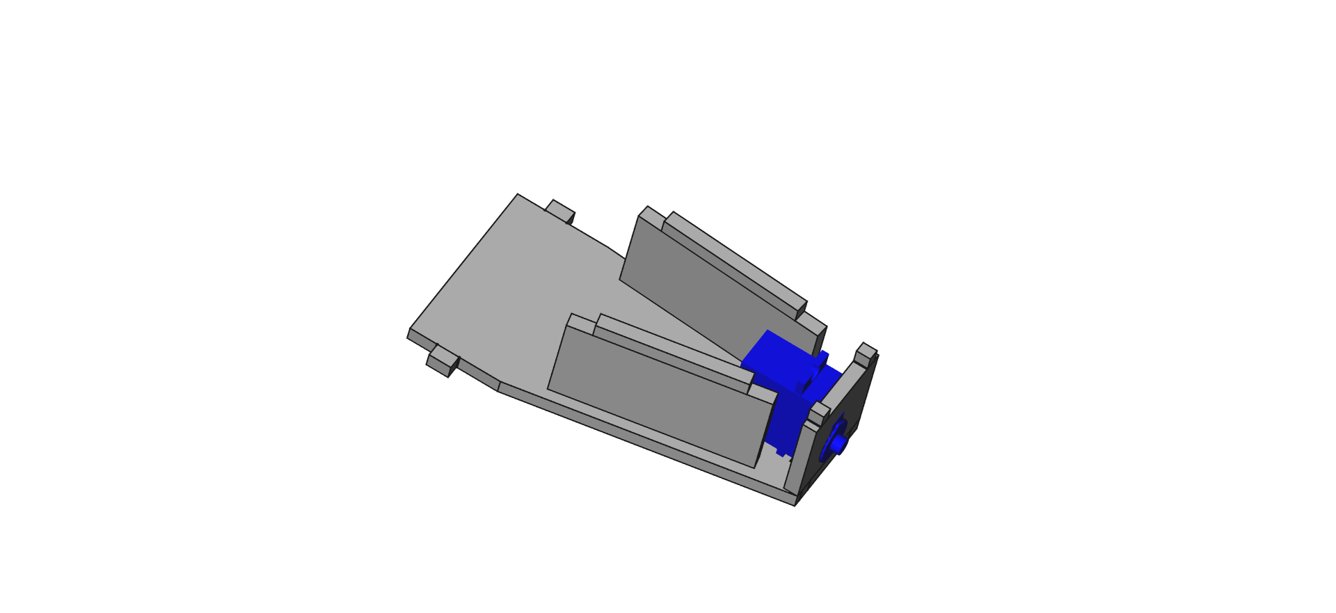
Thigh


Head


The head is where most of your computer electronics go. It is also the part where you get to decide how it should work. You should therefore plan carefully what you intend to do. Maybe you need to drill some holes. Maybe do some sawing, laser cutting or measuring. Do most of that before you assemble the head, a it will be harder afterwards.
Putting It All Together


By now, you should have an impressive pile of parts in front of you. Check that every mirrored part is left/right and nothing is inside out.
Start with the torso, as all the other parts are connected to it somehow.
Use the CAD file for reference if you are in doubt.
Motor Adjustment
Before you secure the servo horns to the servos with the corresponding screws, make sure that the servo position fits the joint angle. This can be done with a simple arduino/Python script, or by using a servo tester. Make sure that the joints have a full range of motion and that the angles fit your programming. More precision now means less work later. Trust me.
Programming
lIllI can be programmed with the software you prefer. Depending on your micro controller, Python, Arduino, Java or C++ will be the most probable choice.
But I think this instructable is long enough as it is.
Have fun!