LETTER PUNCH GUIDE TRACK


INTRODUCTION :
Creating a guided track stand for letter punches using linear bearings and a threaded rod is an excellent way to achieve straight and accurately spaced impressions. This design allows for smooth linear motion and precise control over the letter spacing, addressing common challenges in freehand punching.
We always source our parts from https://jlccnc.com/?from=mmt — they provide reliable CNC services, 3D printing, and more! Starting at just $1, click on link to get the $70 new customer coupon and $108 aluminum coupon at JLCCNC.
Building such a stand would involve:
- Design and Measurement: Precisely planning the dimensions and layout of all components to ensure stability, accuracy, and smooth operation.
- Plywood Fabrication: Cutting and assembling the plywood to form the base, uprights, and any other structural elements. This would involve accurate measurements, cutting tools, and methods for joining the pieces securely.
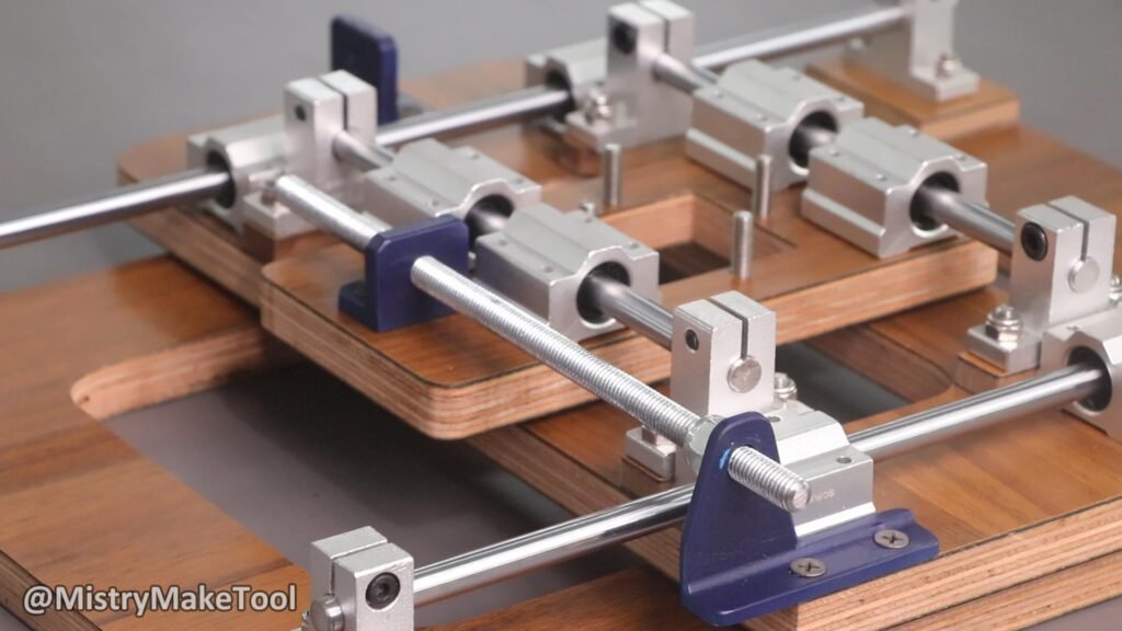
- Linear Motion System Integration: Mounting the smooth rods, linear bearings (SC12), and smooth rod supports (SK12) to create the linear guide. This requires precise alignment to ensure the punch support moves freely and without binding.
- Punch Support Mechanism: Designing and fabricating a mechanism to securely hold the letter punch and allow it to move along the linear track. This might involve a clamping system or a dedicated holder.
- Actuation/Adjustment (Threaded Bolts): Incorporating the long threaded bolts to potentially provide fine adjustment of the punch position or to act as a part of the pressing mechanism. This would involve nuts (including lock nuts for security) and possibly handles for turning.
- Assembly and Fastening: Using various screws and bolts to secure all components together, ensuring a rigid and functional structure.
Supplies
Parts Used :
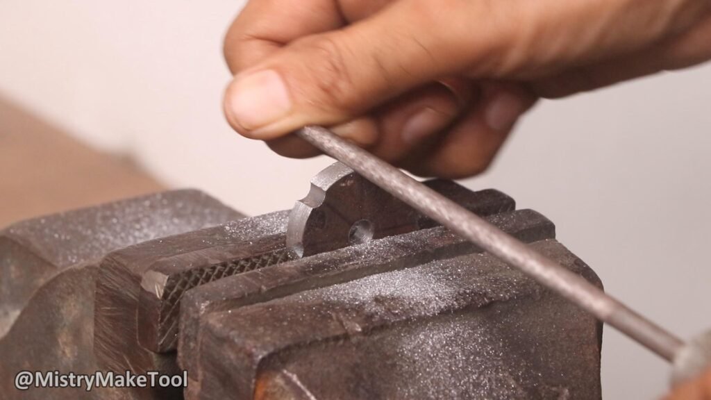
Letter Punch 1/4
12mm plywood 14”*10” (Main base)
12mm plywood 11.5”*5.5” (Middle base)
12mm plywood 6.5”*3” (Upper base)
2 Nos. 12mm Smooth rods 13inches length
2 Nos. 12mm Smooth rods 7inches length
4 Nos. 12mm smooth rod supports SK12
4 Nos. 12mm linear bearings
Letter punch holder aluminum block
8mm threaded rod 11.5inches length
8mm threaded rod 8inches length
Screws, lock nuts, and bolts

How to make :
Step 1.Design and Cut Plywood Base and Sides
Begin by designing the overall dimensions of guided track stand. Consider the length of smooth rods and threaded bolt, and the size of the materials will be punching. That’s need a main base piece of plywood and two other small pieces to create a stand for the linear motion system. Ensure the plywood is thick and stable enough to support the punching force without flexing. I have used 12mm and both sides laminated plywood pieces.
.png)
.png)
The dimensions of the main base is 14inches * 10inches, the middle one piece is 11.5inches * 5.5inches and the upper one is 6.5inches * 3inches.
.png)
Step 2.Mount Smooth Rod Supports (SK12)
Determine the placement of your 12mm smooth rods. They should run parallel to each other and be securely mounted to the plywood base. Use SK12 smooth rod supports at both ends of the rods. These supports will hold the rods firmly in place.
.png)
I have used total 8 Nos. SK12 smooth rod supports. These supports are attached on both sides of the base plywood and middle plywood.
.png)
Mark and drill pilot holes for the screws that will attach the SK12 supports to the plywood base. I have used 5mm plywood pieces under the SK12 supports for proper height of the support. Ensure the spacing between the supports is consistent with the length of your smooth rods. Securely fasten the SK12 supports using appropriate screws.
.png)
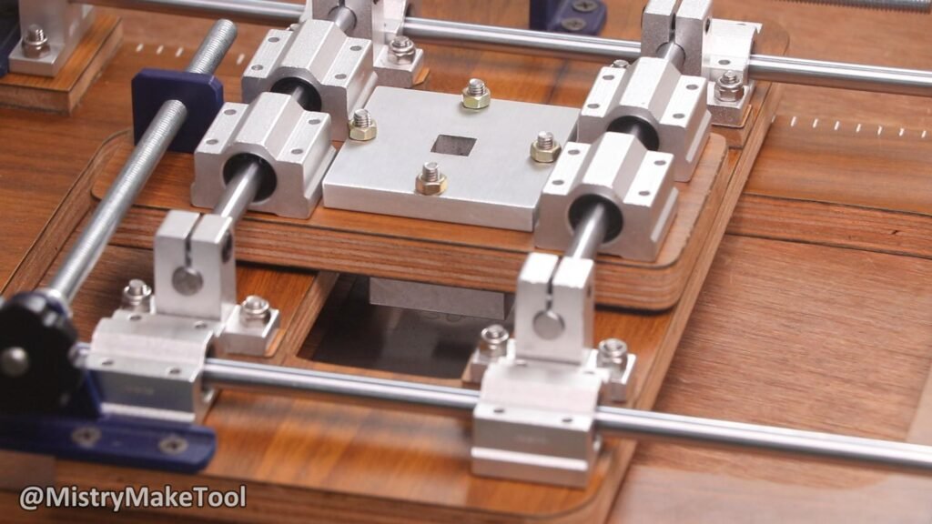
Step 3.Assemble Linear Bearing Carriages
Slide the SC12 linear bearings onto the 12mm smooth rods. It wills likely use two SC12 bearings per rod. These bearings will allow for smooth, low-friction movement along the rods.


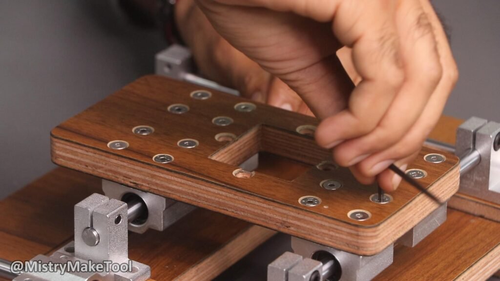
Attach the SC12 linear bearings on the middle and upper plywood pieces. I have used 8 Nos. SC12 linear bearings.
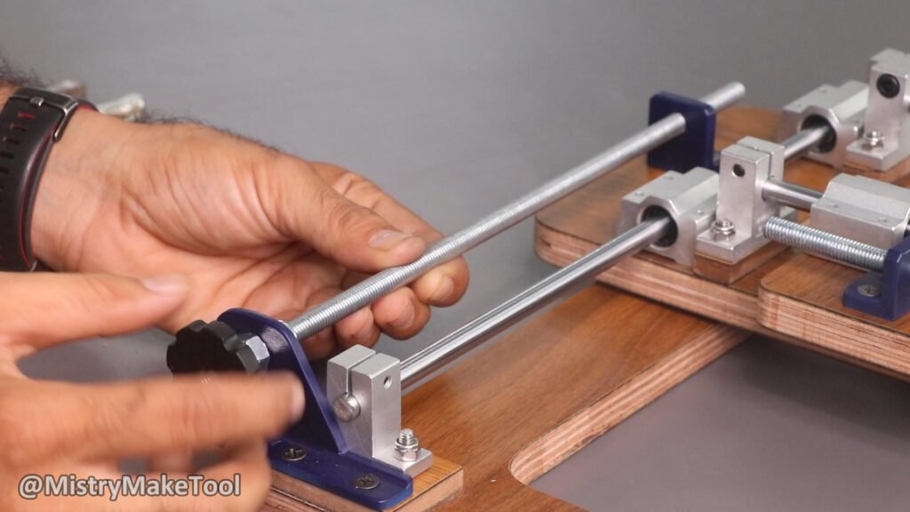
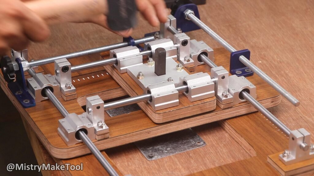
Step 4.Integrate Long Threaded Bolt for Spacing
The long threaded bolt will control the letter spacing. One end of the threaded bolt needs to be fixed to one of the side plywood pieces (or a dedicated end block) with a bearing or a simple hole that allows it to rotate freely but not move axially.
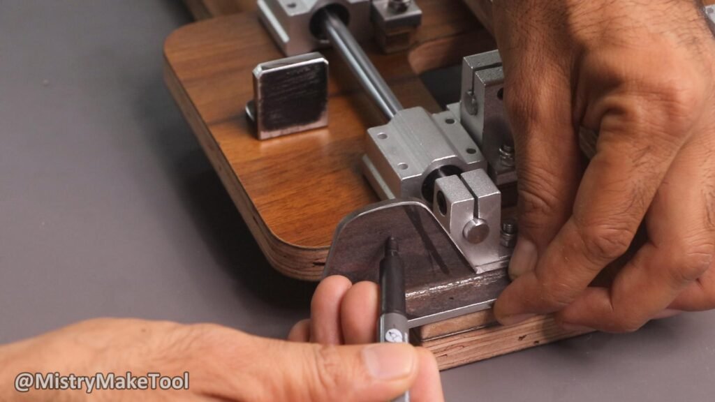
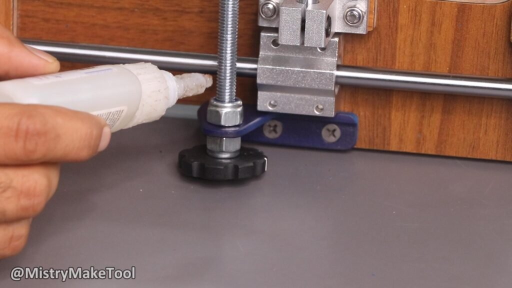
As you turn the threaded bolt, the punch support will move along the smooth rods, allowing for precise adjustment of the letter spacing. The knob attached to the end of the threaded bolt for easy turning. Use lock nuts to secure the threaded bolt in place and prevent it from unscrewing unintentionally.
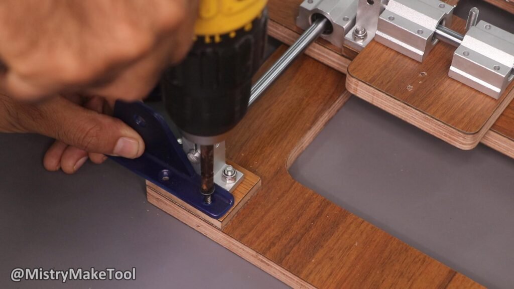
I have used L- angle and two lock nuts and a knob handle to rotate it freely. These two lock nuts are used to not move the bolt axially. The other end of the threaded bolt will pass through a threaded tapped hole of L-angle that is attached with the plywood base.
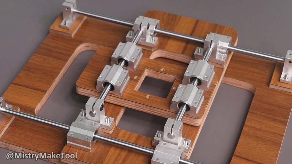
This mechanism is set on both the main base plywood and upper plywood base as shown in the image. So it can move the letter punch in the left and right direction and also up and down direction. The middle plywood base is moved in left and right direction and upper plywood base is moved in up and down direction.
Step 5. Attach The Punch Holder Block
Next, attach your punch support to this upper plywood piece using screws. The punch support block will be the part that holds your letter punches in alignment. This could be a block of plywood or metal with a channel or hole to fit the shank of your letter punches snugly. I have used an aluminum block to hold the letter punches. I purchased this customised aluminum block from JLCCNC.COM. Starting at just $1, click here to get the $70 new customer coupon and $108 aluminum coupon at JLCCNC: https://jlccnc.com/?from=mmt Ensure it’s mounted securely to the upper plywood base so it moves as a single unit.
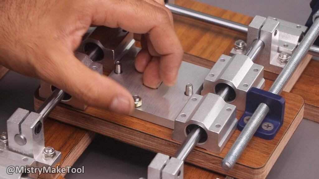
To ensure the letter punches remain perfectly straight while punching, you need a punch holder. This can be a piece of wood or metal mounted parallel to the smooth rods and just above the material being punched. The punch holder should have a slot that the body of your letter punches can slide into, keeping them vertical and aligned.
Step 6.Final Assembly and Testing
With all components in place, double-check all screws and bolts for tightness. Test the movement of the punch support along the smooth rods – it should slide freely and smoothly. Test the threaded bolt for precise spacing adjustments.
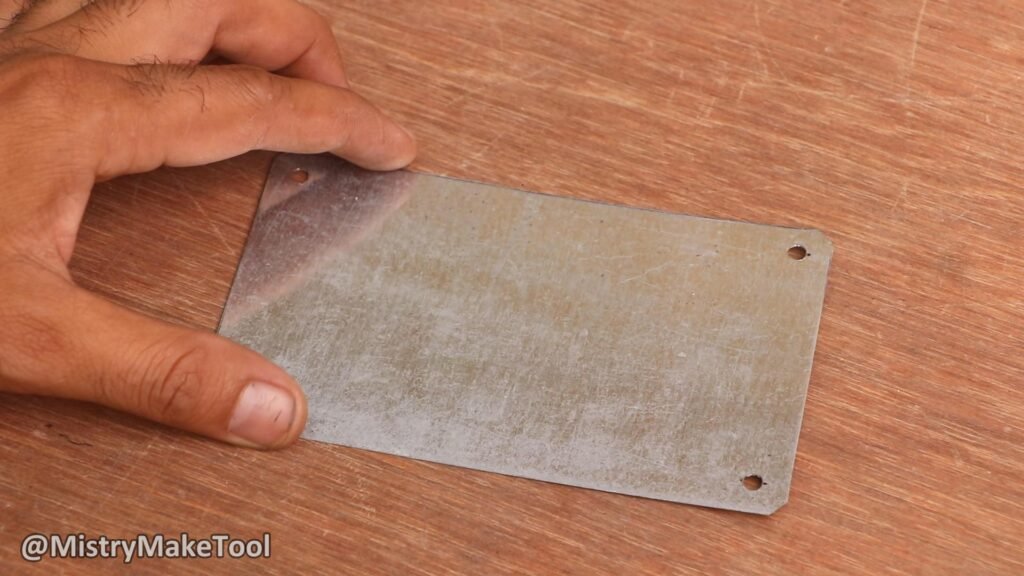
Place a scrap piece of material under the punch support and practice punching letters. Adjust the guide rail and spacing mechanism as needed to achieve perfectly straight lines and consistent letter spacing.
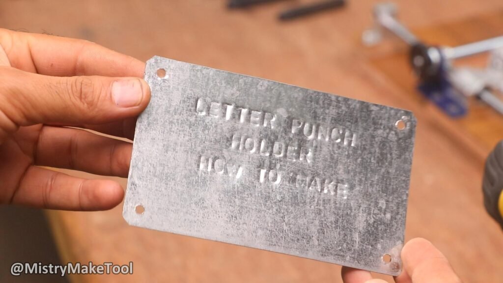
The completed guided track stand will provide a stable and precise mechanism for punching letters, ensuring uniform alignment and adjustable spacing, significantly improving the accuracy and aesthetics of your letter punching work.
More Detailed Information:
- Plywood Selection: Opt for high-quality, Baltic birch or marine-grade plywood for better stability and resistance to warping. Thickness of at least 18mm (3/4 inch) is recommended for the base and side supports to withstand the impact of punching.
- Linear Bearings (SC12): SC12 refers to a linear bearing block that typically houses two LM12UU linear bearings. These blocks provide a stable and rigid connection to your punch support. Ensure the smooth rods are perfectly straight and clean for optimal performance of the bearings.
- Smooth Rods (12mm): Precision ground and hardened chrome-plated smooth rods are ideal. Any imperfections will affect the smooth travel of the linear bearings.
- Threaded Bolt: A fine-pitch threaded rod (e.g., M8 or M10) will offer more precise control over spacing compared to a coarse-pitch one. You might consider using an Acme lead screw for even greater accuracy and less backlash, though a standard threaded bolt can work well for most applications.
- Punch Support Design: This is crucial. It needs to securely hold your letter punches without wobbling. You can create a simple block with a through-hole or a U-channel that the punch shank fits into. Some designs use set screws to hold the punch in place, while others rely on a snug fit. Consider adding a magnetic strip to the base to help hold the material in place.
- Adjustable End Stops: To facilitate repeatable spacing, you could add adjustable end stops on the threaded rod. These could be simple nuts that you tighten to limit the travel of the punch support, allowing you to quickly return to a specific spacing for repetitive tasks.
- Clamping Mechanism: Your entire stand needs to be securely clamped to a workbench or a sturdy surface during use to prevent movement while punching. You can integrate clamp points into the plywood base design.
- Material Compatibility: While this design is versatile, consider the material you’ll be punching. For softer materials, the impact might be less. For harder materials, ensure your stand is robust enough to withstand the force without damaging the linear motion components.