LED Ping Pong With Shift Register
by TechMartian in Circuits > Arduino
2037 Views, 1 Favorites, 0 Comments
LED Ping Pong With Shift Register
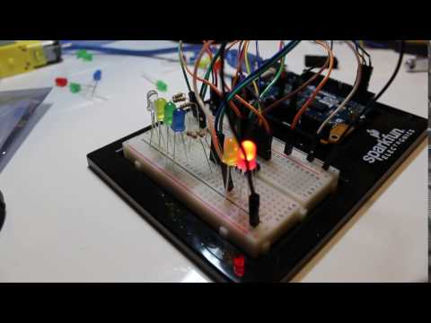
Shift registers are essential components for multiplexing a lot of different components in this case 8 LEDs into 3 input signals which can be programmed to make unique patterns like this LED Ping Pong Effect.
This also makes for a cool Battlestar Galactica Larson Scanner.
BoM

* Shift Register IC
* Arduino 101
* Breadboard
* 8x LEDs
* 8x 100Ω resistors
Wiring the Shift Register


- Connect the Arduino 3.3V to the breadboard power rail and GND to the breadboard ground rai.
- Place the shift register on the breadboard with the top notch facing the top, this will indicate where pin one isConnect pin 10 and 16 on the shift register to the 3.3V power rail.
- Connect pin 8 and pin 13 on the shift register to the ground rail of the breadboard.
- Connect pin 11, 12 and 14 from the shift register to pins 2, 3, and 4 to the breadboard, respectively.
Wiring the LEDs

- Design a pattern for which you want the LED colours to bounced back like a ping pong ball (in a court with at least two capable players, unlike me)
- Connect the anode of each of the 8 LEDs to a 100Ω resistor
- Connect the cathode of each of the 8 LEDs to the ground rail of the breadboard.
- Connect the ground rail of the breadboard to the GND pin of the Arduino board.
- Connect the remaining unconnected end of the resistor to pins 1-7 and 15 of the shift register. It is important the LEDs are connected in consecutive order, otherwise the ping pong patter will not be consistent. Consult the schematic for more details.
Coding

int datapin = 2;
int clockpin = 3; int latchpin = 4;
// We'll also declare a global variable for the data we're // sending to the shift register:
byte data = 0;
void setup() { // Set the three SPI pins to be outputs:pinMode(datapin, OUTPUT); pinMode(clockpin, OUTPUT); pinMode(latchpin, OUTPUT); }
void loop() {oneAfterAnother(); // All on, all off
}
void shiftWrite(int desiredPin, boolean desiredState)
{ // First we'll alter the global variable "data," changing the // desired bit to 1 or 0:bitWrite(data,desiredPin,desiredState);
// Now we'll actually send that data to the shift register. // The shiftOut() function does all the hard work of // manipulating the data and clock pins to move the data // into the shift register:
shiftOut(datapin, clockpin, MSBFIRST, data);
// Once the data is in the shift register, we still need to // make it appear at the outputs. We'll toggle the state of // the latchPin, which will signal the shift register to "latch" // the data to the outputs. (Latch activates on the high-to // -low transition).
digitalWrite(latchpin, HIGH); digitalWrite(latchpin, LOW); }
void oneAfterAnother() { int index; int delayTime = 100; // Time (milliseconds) to pause between LEDs // Make this smaller for faster switching// Turn all the LEDs on:
// This for() loop will step index from 0 to 7 // (putting "++" after a variable means add one to it) // and will then use digitalWrite() to turn that LED on.
for(index = 0; index <= 7; index++) { shiftWrite(index, HIGH); delay(delayTime); }// Turn all the LEDs off:
// This for() loop will step index from 7 to 0 // (putting "--" after a variable means subtract one from it) // and will then use digitalWrite() to turn that LED off.
for(index = 7; index >= 0; index--) { shiftWrite(index, LOW); delay(delayTime); } }