LED Pineapple Gypsy Sign and Stand
by smundon in Workshop > Lighting
1994 Views, 14 Favorites, 0 Comments
LED Pineapple Gypsy Sign and Stand
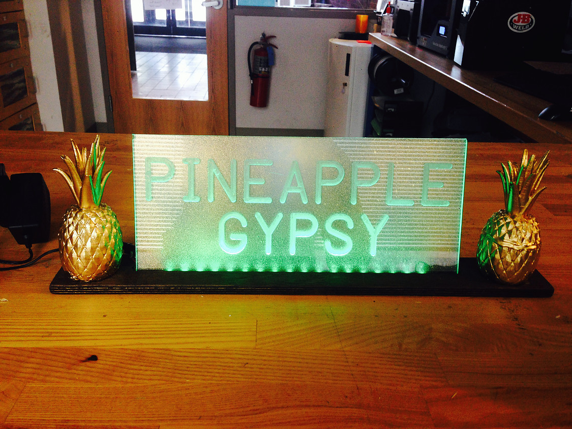
OBJECTIVE:
Create a Pineapple Gypsy engraved LED, acrylic sign with a wooden mount. Extra: Add two, 3D Printed pineapples to enhance the pineapple-ness!
Materials:
Materials are subject to the user’s preference so if you prefer using a different plastic or a different styled mount, please feel free to utilize your own ideas.
- 1/4” Acrylic Sheet
- 1/2” sanded plywood (chose this because it was lying around the shop)
- Rated 12V, 1A RGB strips (choose based on preference)
- Spray Paint (I chose blue and gold)
- XTC-3D *3D prints not discussed in this tutorial*
- Red and black 28AWG wire
- 1 roll of PLA (filament for the 3D printer) *3D prints not discussed in this tutorial*
- Power Adapter (Must match with LED rating (12V, 1A))
- Barrel Power Connectors
TOOLS:
- NC Mill (assorted flat end mills, ball end mills, chuck and drill bits)
- 3D Printer (Makerware Software) *3D prints not discussed in this tutorial*
- Band Saw
- Soldering Iron (Use vent when soldering)
- Wood Finish
- Sanding Paper
- Rulers
- Writing Utensil
- Wire cutters
- Wire Strippers
- Rag/Paint brush (for wood finish)
Laying Out the Acrylic
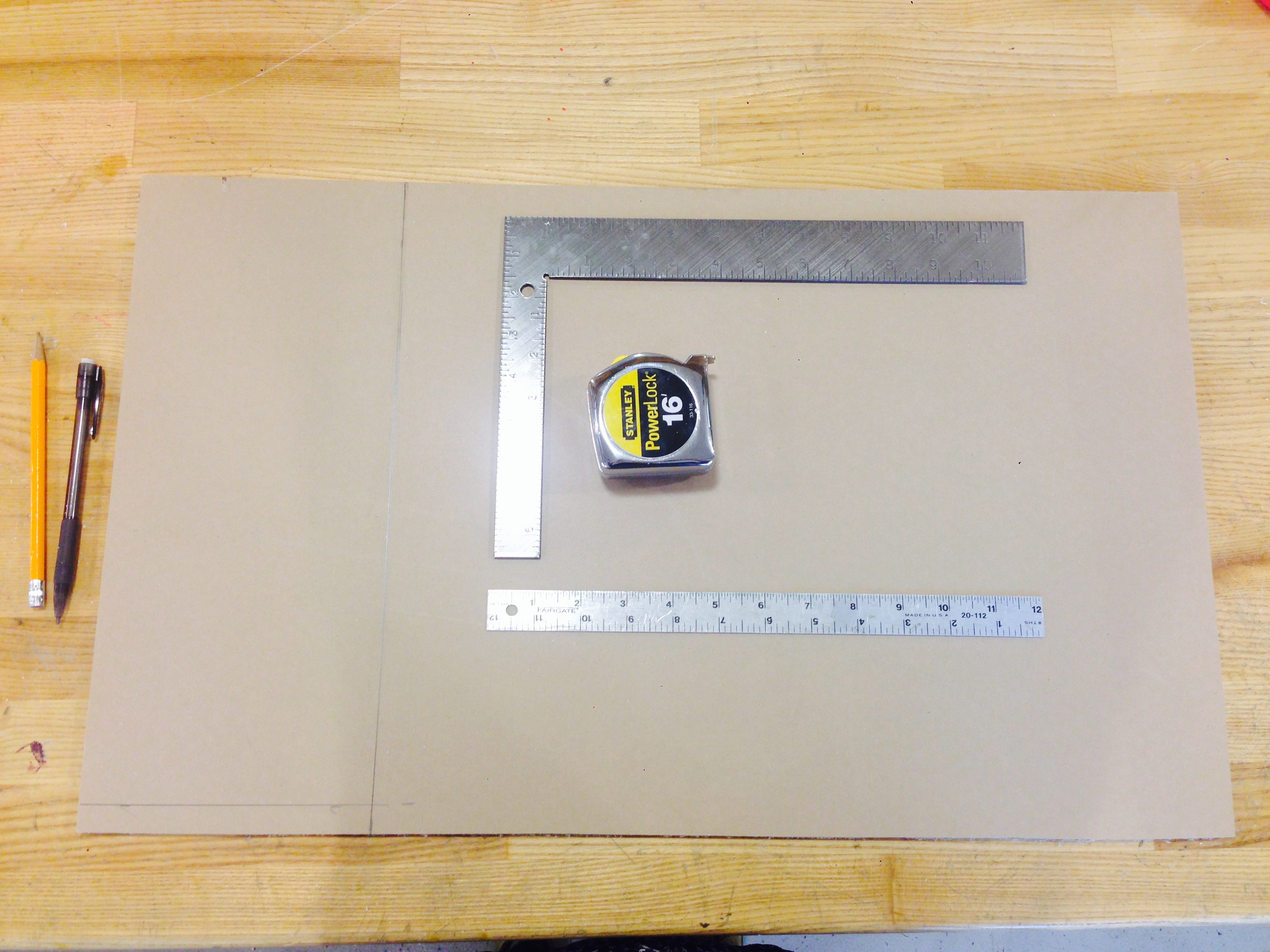
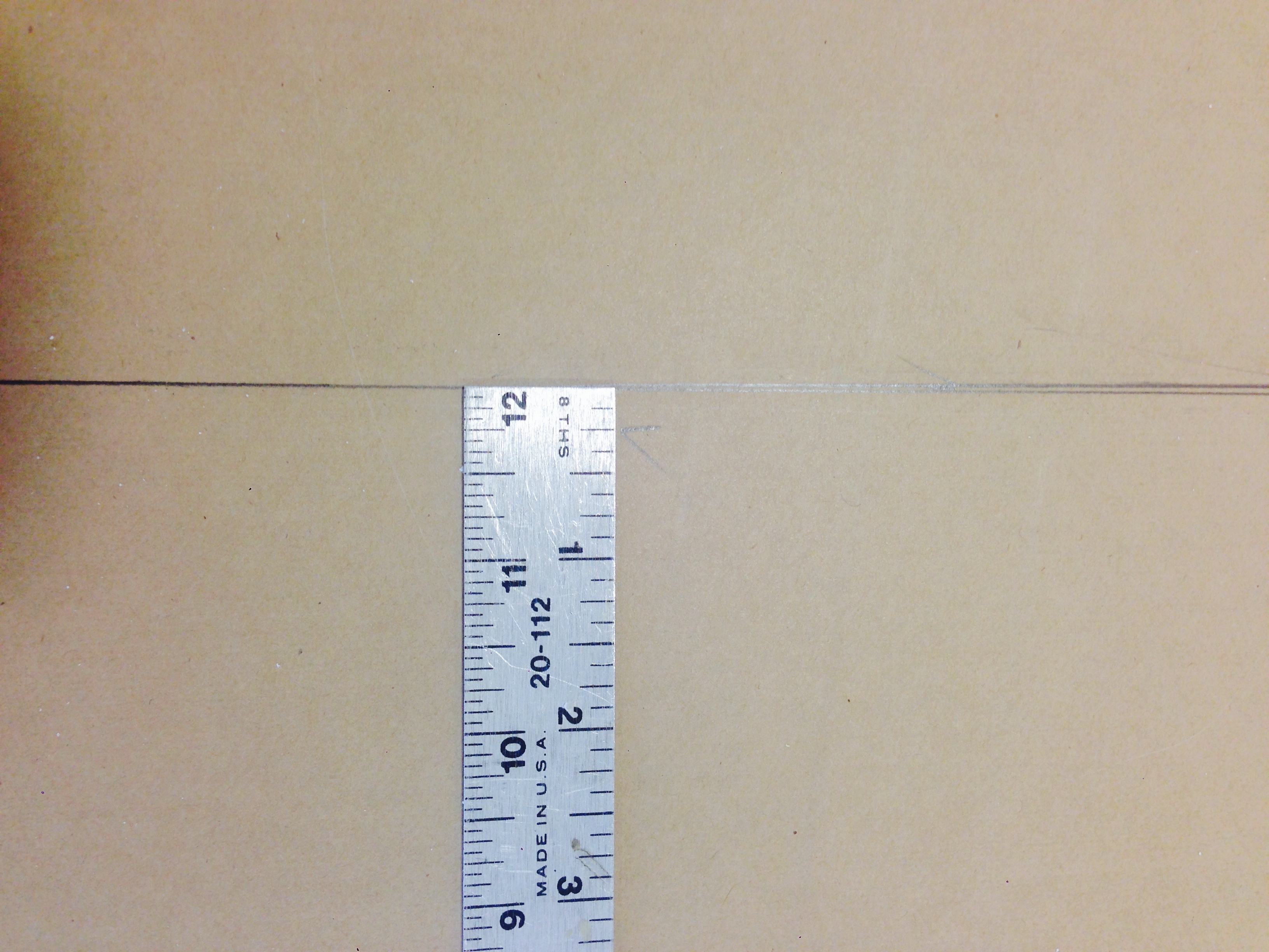
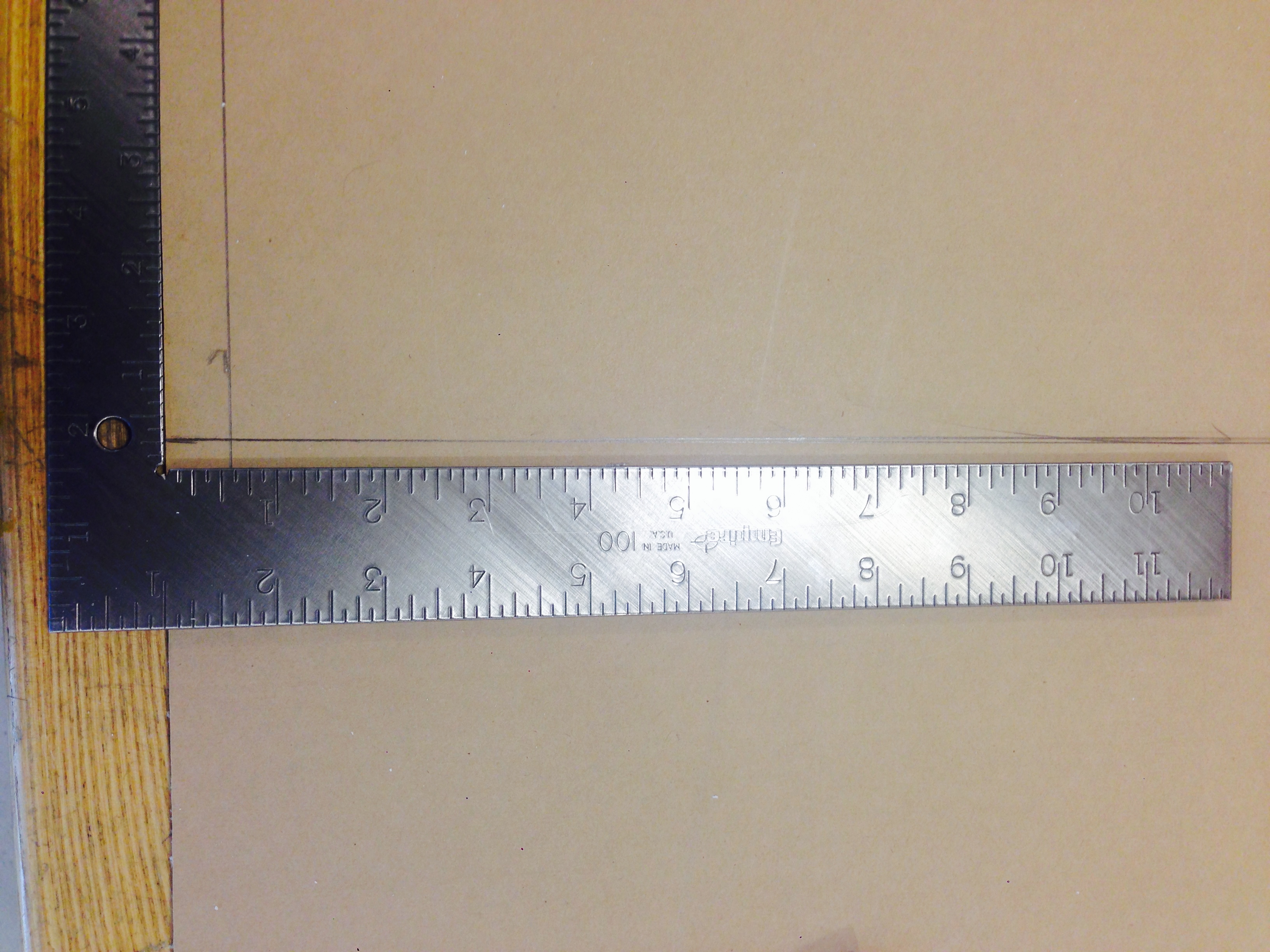
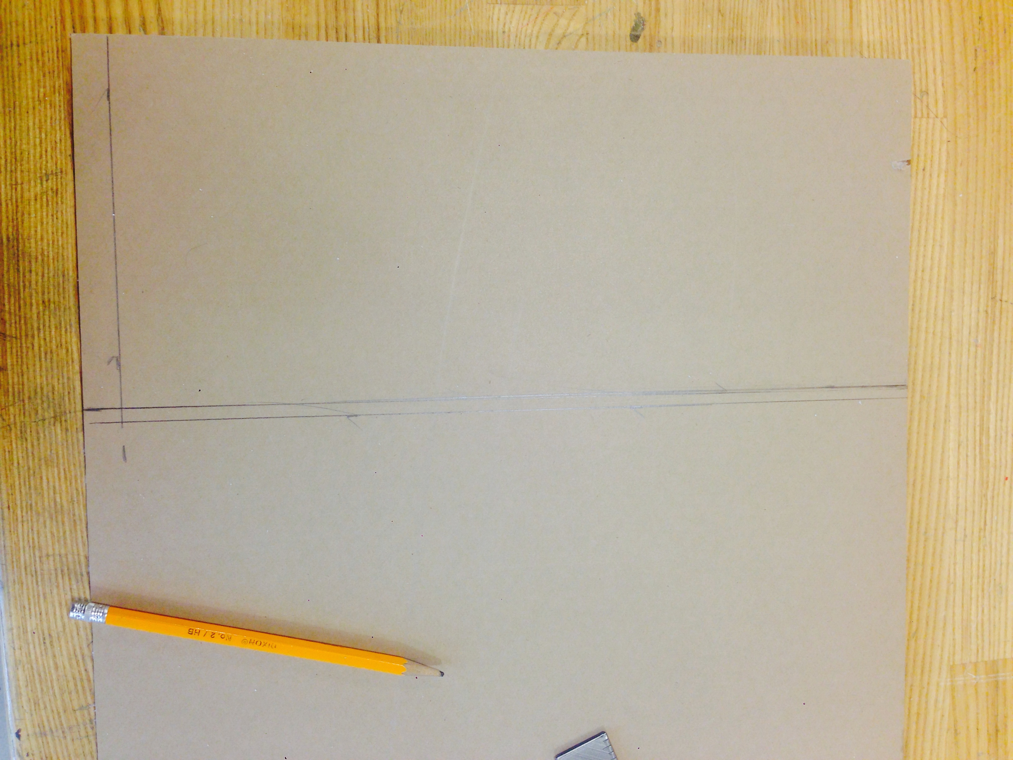
Choose a 1/4” piece of acrylic from the stock pile and lay out the dimensions accordingly. Do not peel off the paper from the acrylic! If the acrylic is longer than that of the ruler, use this technique to draw out a perfectly straight line:
- Measure out the width of your acrylic (I used 6”) and mark the measurement on either side of the acrylic piece.
- Using either a framing square (L shaped ruler) or a regular ruler, line up your marks and draw a straight-line. Use check marks for each marked measurement.
After laying out the length of the acrylic (I used 14”), draw another line about a 1/4” outside each original mark.
- This is the line we will use as a guide on the bandsaw.
Cut the Acrylic
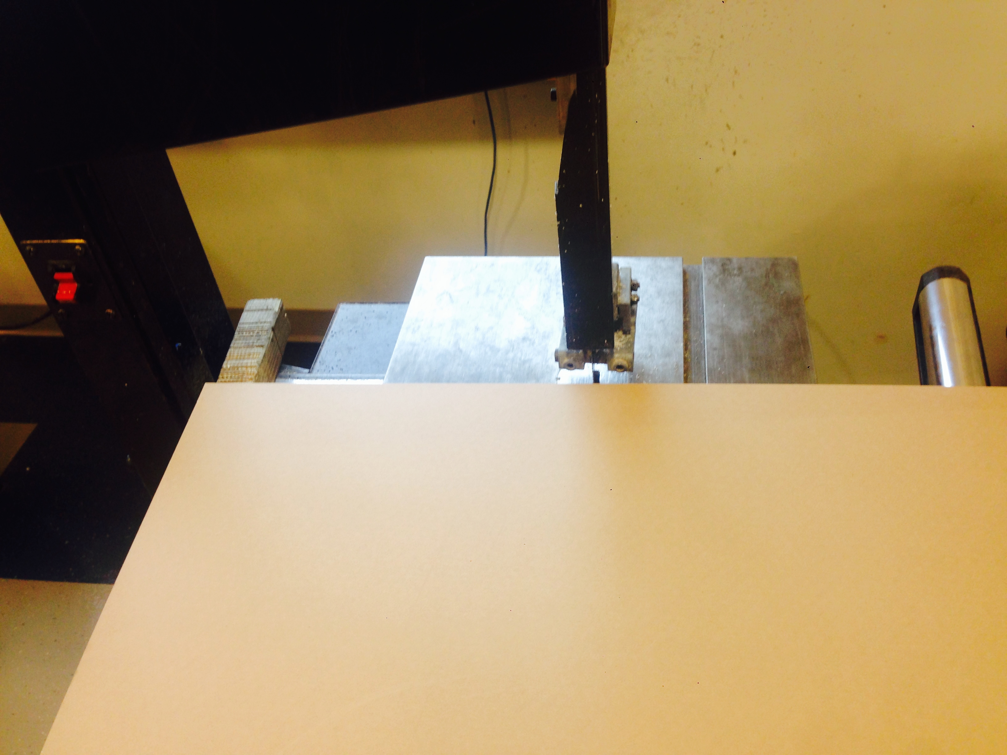
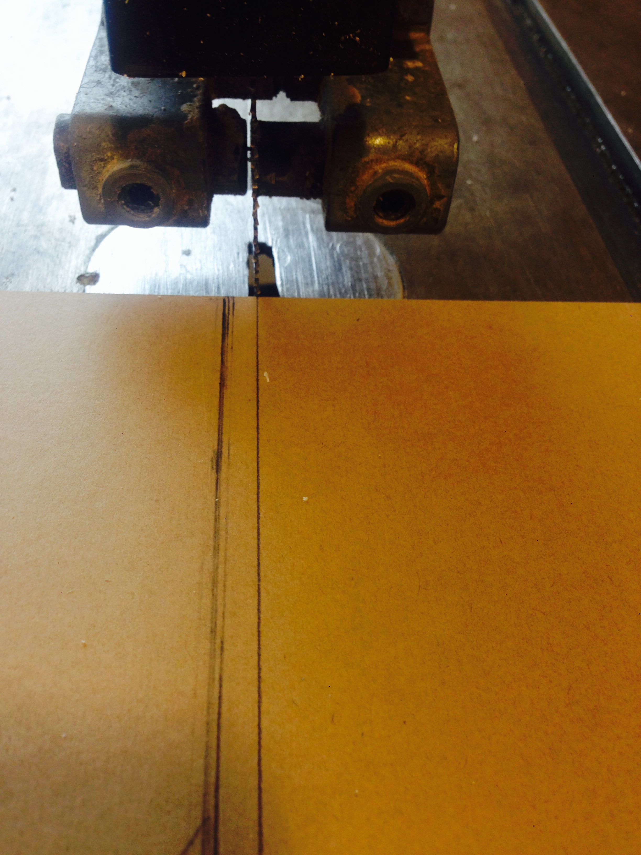
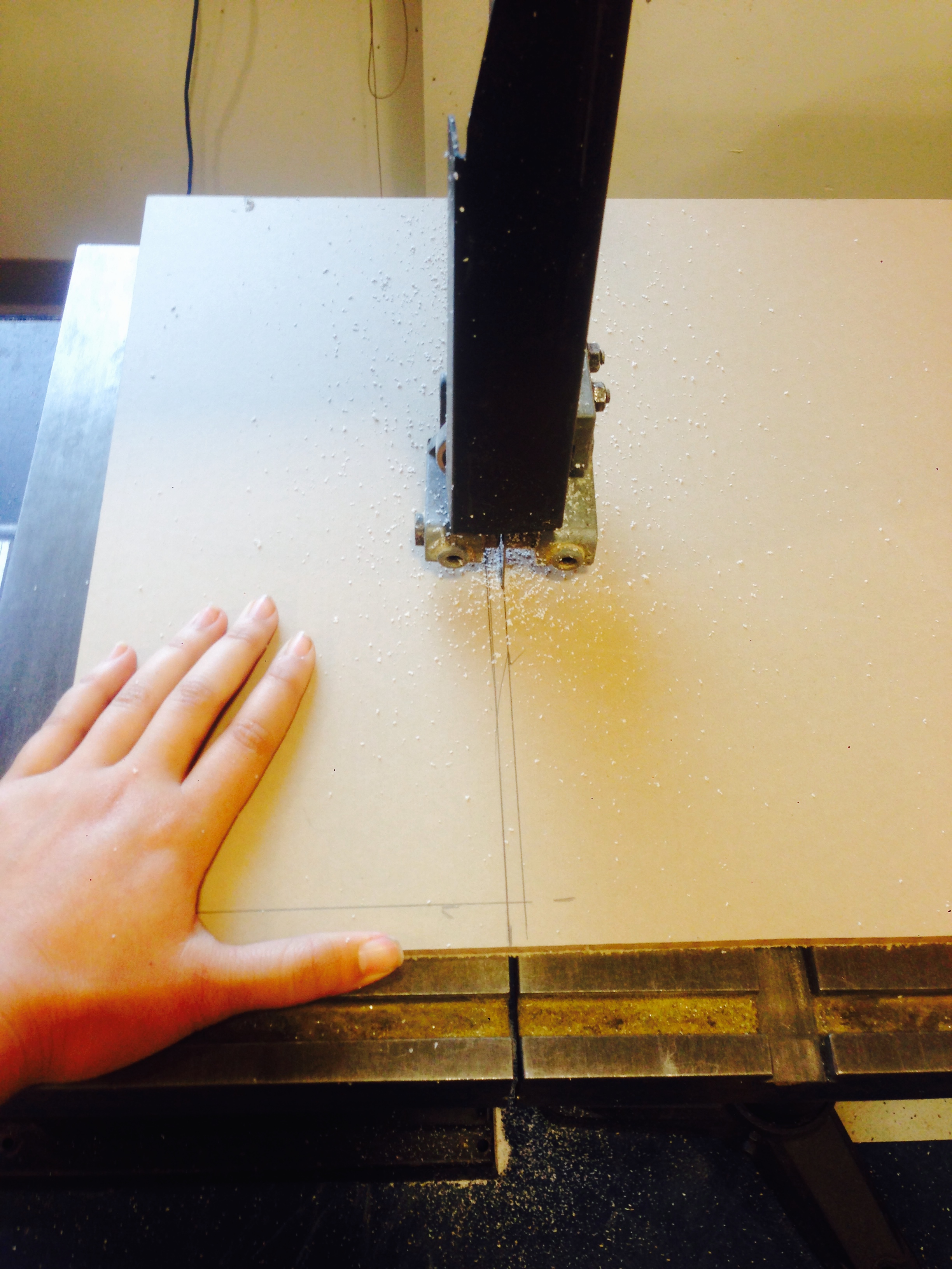
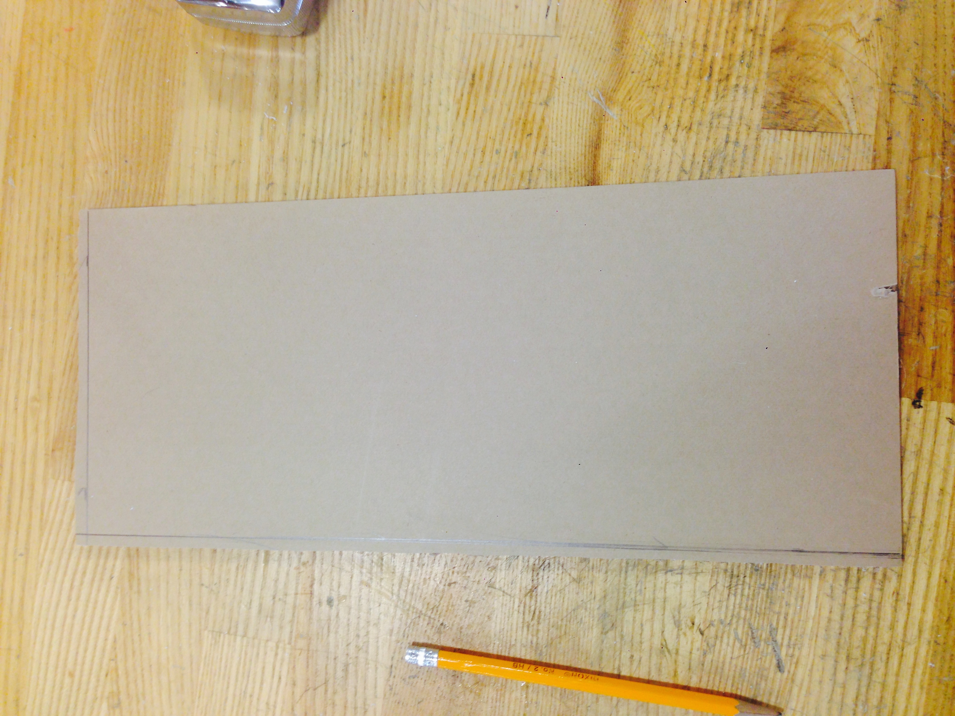
- Since the bandsaw rarely ever gives the user a straight cut unless they are a practiced carpenter/machinist, use the second line, we marked out earlier, as a guide.
- Make sure that the bandsaw guard is about 1/4” above the acrylic before cutting (if limitations allow). Remember, the less blade is exposed, the safer the user will be. Always set the blade guide just high enough to clear the part you are cutting.
- Acrylic is a material that has a low melting point. In my experience, acrylic will melt at high feed rates and crack at low feed rates, therefore find a steady speed to push the acrylic at that isn't too fast or too slow. If you are a novice in machining, this experience will come in time through practice. Enough experience will allow you to physically feel the optimal speeds during machining.
- Apply a steady pressure when easing the acrylic across the blade. Ease up every once in while to give the blade a break, especially if the bandsaw is relatively ancient.
- If you do not have a bandsaw, you could use a jigsaw to cut the acrylic; however, jigsaws are a bit more difficult to control when you're a novice. Please use the right safety measures when using the jigsaw or the bandsaw.
Finish the Edges of the Acrylic
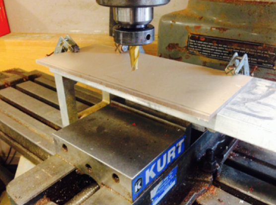
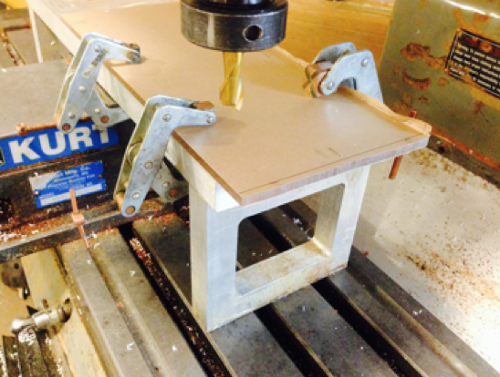
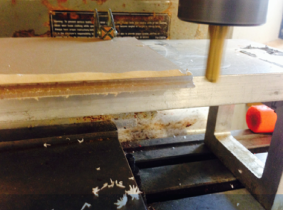
- In order to make both sides of the acrylic parallel to one another, we will manually mill the edges off along the outer side of the first line of measurements we made.
- Secure the acrylic to the vice grip or the stand. Make sure that the side you are milling into clears the edge of the vice grip or the stand by at least an inch. Also make sure that the edges of the acrylic are parallel to that of the table’s edges so that a straight cut will be performed.
- Use a flat end mill thats diameter is larger than that of the length being milled (the edge of the acrylic to the first measurement made). Also make sure that this end mill’s diameter is a bit larger than the acrylic’s thickness. I used a 1/2” end mill.
- Line up the end mill to the starting position located on the acrylic using the x, y and z axes.
- Before turning on the spindle, make sure the spindle is about an inch away from the edge of the acrylic.
- Also make sure that the machine is in high gear.
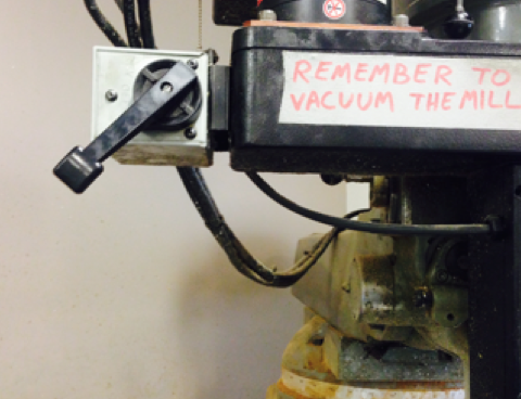
- Turn on the spindle by pushing the upper lever downwards (pictured in step 9). However, the direction in which you turn the lever (up or down) is determined by whether you're using conventional milling or climb milling. Will the spindle be spinning in the opposite direction of the desired cut or will the spindle be spinning in the direction of the desired cut? Learn more about it here: http://www.datron.com/blog/climb-milling-vs-conventional-milling/.
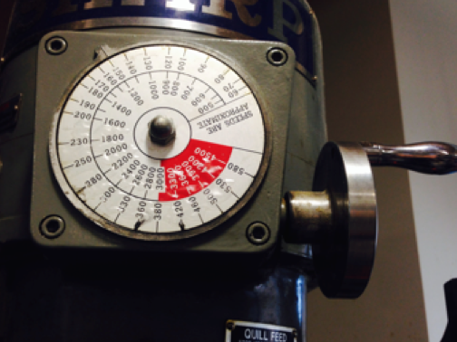
- Once the spindle is on, adjust the speed of the acrylic between 1100-1500 rpms. The spindle must always be on before changing the spindle speeds!
- Since you are manually moving the table to do the finishing pass, the feed rate isn’t really something that can be determined. Instead move the table fast enough as to not crack the acrylic, but slow enough to not melt the acrylic.
- When milling along the length of the acrylic, only move the x axis. When milling along the width of the piece, only move along the y axis.
- Each pass should be no more than -0.05” in depth. Therefore multiple passes must be done in order to mill off the edges. You can keep track of the coordinates by using the mill’s monitor by pressing the button DRO. Use the air hose to clear the debris off of the end mill. Do not mill the entire edge off in one pass, the acrylic will shatter!
- The bottom of the end mill should be below the bottom surface of the acrylic before performing a finishing pass.
Rejoice in the Beautifully Milled Acrylic Edges!
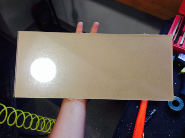
Now peel off the paper from one side of the acrylic sheet!
Engraving the Acrylic: Part I
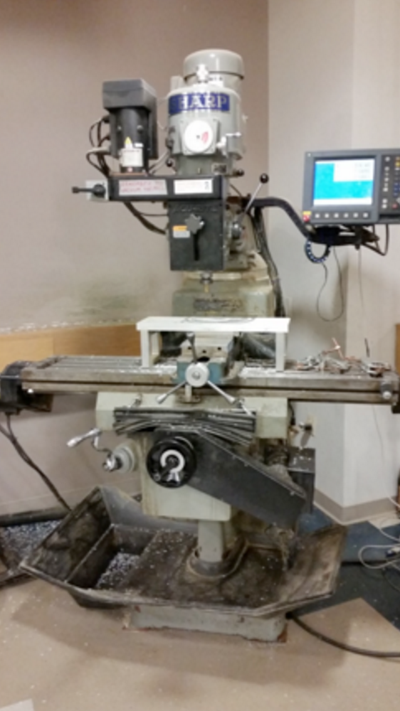
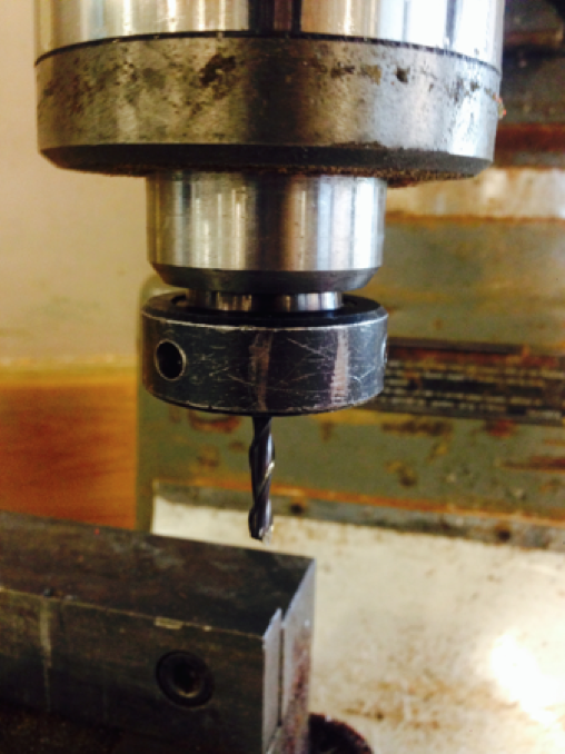
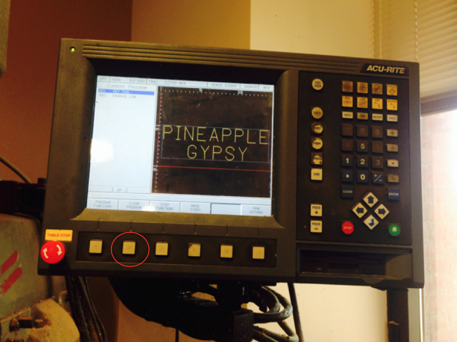
Warning I: This is a detailed guide as to how to operate a NC Mill. For novices, an NC Mill is a numerically controlled mill (featured above), which allows the user to program and create tool path functions. Materials commonly milled on this machine are wood, plastic, aluminum and steel. Skim through this part of the tutorial if you already have experience in operating this mill or if you're using a different tool for engraving.
Warning II: I am not a machinist, simply a student advisor for a lab that has had extensive training on each of these machines. The speeds, feeds and advice I post are from my experience as to what has and hasn't worked for my projects. If you would like a more thorough understanding and advice from professionals please look at the link below. Also, feel free to critique and comment on my advice/instructions since I'm always looking for new ways to improve my skill set!
- First, change the end mill to a 1/4” ball end mill and place the collet in the spindle. Please refer to this website for more detailed instructions as to how to choose your speeds and feeds for an end mill based on the size of your acrylic and geometry to be milled: https://othermachine.co/support/materials/acrylic/.
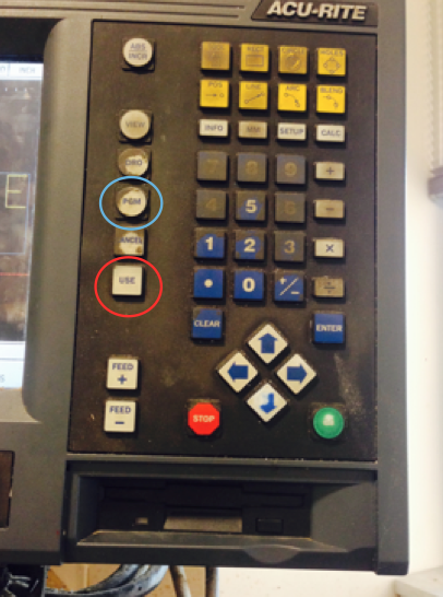
- Next clear any existing program by pressing the Clear Program button circled above.
Engraving the Acrylic: Part II
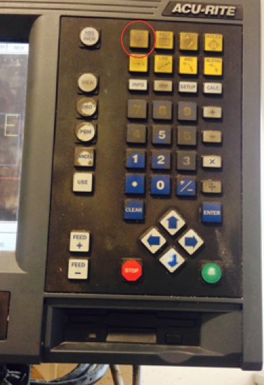
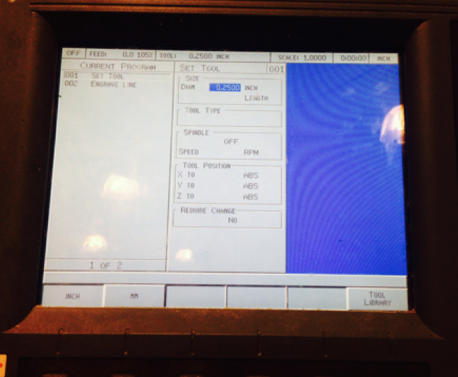
- To begin entering a program, start by pressing TOOL and then inputting your tool diameter (0.25”).
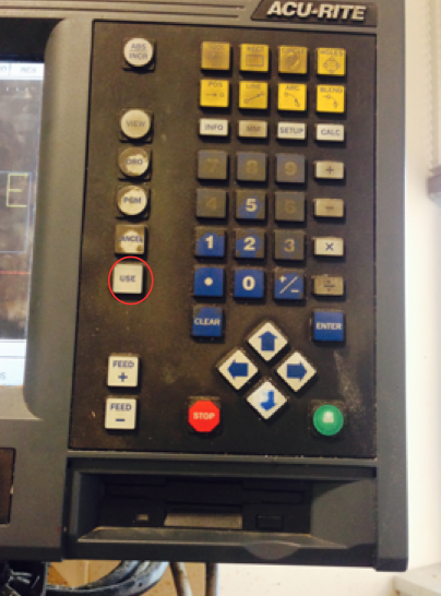
- Ignore the rest of the options and then click USE.
Engraving the Acrylic: Part III
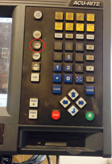
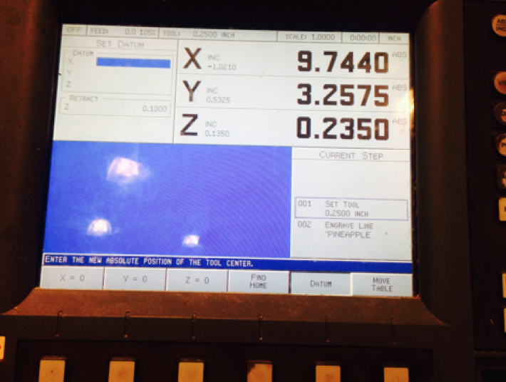
- Clamp down your acrylic similar to that when manually milling. If you are only engraving a small depth into a piece, the support material underneath the acrylic is unnecessary. However, if you plan to mill slots, holes, or other geometries that will go through the acrylic, a support piece is necessary.
- We find the origin by pressing the button DRO. This will take us to the next screen, which displays the x, y, and z coordinates.
- Choose the leftmost, bottom corner to be the origin of the acrylic. Zero each axis by placing the end mill against the left edge of the acrylic. Press DATUM and then press X=0. Next press USE. Since we want the origin to be the center of the end mill, move the end mill above the acrylic in the positive x direction about the length of the radius of your edge finder.
- Press DATUM once again and zero the x-axis.
- Choose the next side of the acrylic, front-most edge, and place the end mill against it. Press DATUM and then press Y=0. Next press USE. Since we want the origin to be the center of the end mill, move the end mill above the acrylic in the positive y direction about the length of the radius of your edge finder.
- For the Z-axis, place the end mill a hair length above the acrylic. One can do this by using the cigarette paper trick. Instead of using cigarette paper, take a piece of computer paper, apply oil to the surface and place it on the acrylic. Take the end mill and lower it until it is touching the paper. You can tell that it is above the piece if you tug at the paper and it does not entirely come off or if you turn on the spindle and the paper gets caught on the end mill. I do not recommend turning on the spindle when finding the z-axis manually unless you are experienced. The piece of paper is about 0.001” and therefore once the sweet spot has been found we can set the z-axis to -.001” to find Z=0.
- Make sure that you are satisfied with the z retract and once your are done with this process, press the button PGM labeled with the blue circle.
Engraving the Acrylic: Part IV
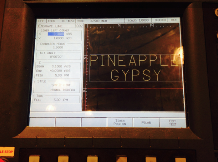
- Once your origin has been established, press MORE OPTIONS until you find ENGRAVE LINE.
- Depending on where you position your clamps and how large your acrylic piece is, place in the necessary compensation needed to move the spindle along the x and y axes to avoid those regions. Due to the way my acrylic was set up, I used 0.5” of compensation along the x-axis and 1” of compensation along the y-axis.
- Before deciding on the character height make sure you know how large your acrylic piece is and the full length of the letters you are engraving. Character width is about 70% of character height. Meaning that based on the character height I chose, it will give me letters that are about 1 3/4” in height and about 1 1/4” in width. This changes depending on the types of letters used. Letters that are thinner, such as As and Is will only be about 40% of the character height widthwise. Furthermore we must also take into account the spaces between each letter, which is measured to be about 5/16”.
- Therefore if 7 of my letters are about 1 1/4” in width, 2 of my letters are 3/4” (40%) and there are 8 spaces each 5/16” apart, the total length of my longest word will be about 12 3/4”- 13”. Make sure to compensate a quarter to half an inch.
- Since my acrylic piece is 14” in length, and I estimated my longest word to be 13 inches, it makes sense to have a compensation of 1/2” in the x-axis so that the letters are at least centered lengthwise.
- Since I chose 1.6” in height, there are two lines of words and about 1/2” of space between both of them, the full height would be estimated to about 4”. Meaning that 1” of compensation from the upper right corner will center my phrase widthwise since my acrylic is 6” widthwise.
- Of course you should play with the option and do a few dry runs (we’ll get to this) in order to fully estimate the length and width of your characters. This comes down to practice.
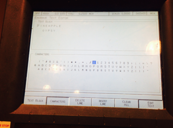
- Once you have chosen a height or even before you have chosen a height, enter your text by pressing EDIT TEXT. This will take you to the screen in the left picture. Choose your characters. If you need to edit a character press TEXT BLOCK to edit and then press CHARACTERS to return the keyboard. Once finished press USE. Remember to always press USE when you are finished with a program and setting an origin.
- Next, choose your Begin Height for the z-axis which should be zero. Your End Height will be the entire depth the end mill plunges. Therefore I chose -0.05. Do not forget to input this value as a negative!
- Since this is acrylic, change the feed rate to 5 imps (inches per minute) for both the z-axis and the tool. The feed rate value will usually be lower for metals and higher for wood and plastics.
- Press USE when satisfied.
Engraving the Acrylic: Part V
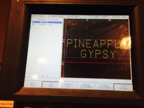
- After pressing USE, it will take you to the home screen where the programs have been set. Place the blue cursor on SET TOOL so that the machine knows where to start the commands from.
- Press RUN OPTIONS and press DRY RUN. You could also do DRY RUN and GRAPHICS ONLY, but I find using DRY RUN more helpful than GRAPHICS ONLY.
- You need to have DRY RUN selected when testing your machining operation!
- Now press GO.
Engraving the Acrylic Part VI
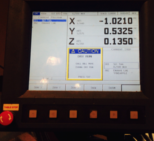
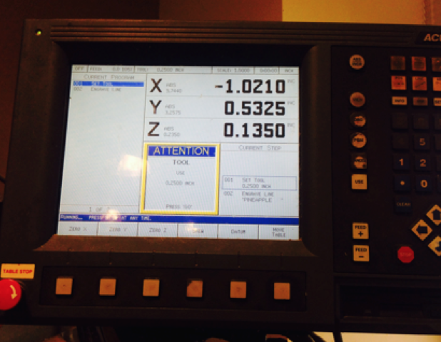
- You will see the Caution Dry Run first, press GO again and you will see the next Caution sign. Remember to keep your hand near TABLE STOP and then press GO a third time. Make sure that the Dry Run coincides with the product you desire.
- Press Run Options, press DRY RUN in order take the program off of DRY RUN and then press Go.
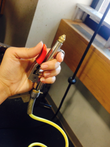
- Remember to use the air hose to keep the end mill free of debris.
Finally After All That...We Have the Beautifully Finished Engraved Acrylic!
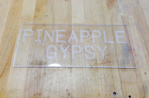
Now you can peel off the last sheet of paper on the acrylic!
Milling the LED Sign Mount
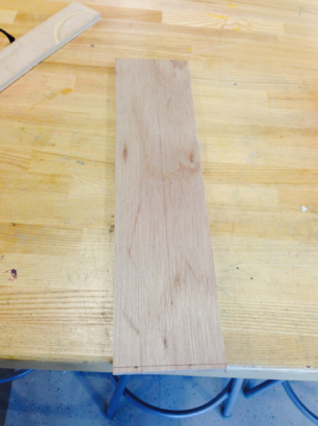
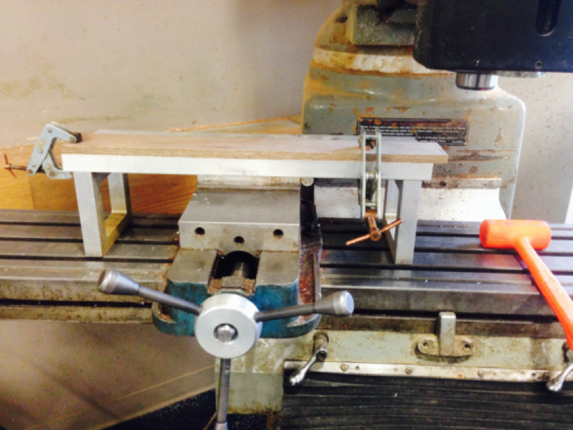
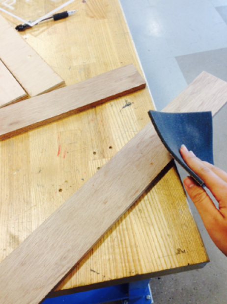
- When you are done laying out the measurements for your mount (I used the measurements 22 3/4”x2 5/8”x3/8”), load the mount onto the mill and manually mill off the edges similar to that that of the acrylic sign. We want to create straight, parallel sides. Set your spindle to about 1400 rpms and move the table slow enough to where it doesn't burn the wood; similar to that of acrylic.
- Once your part has been milled, sand the edges and corners down for safety reasons. Use regular grit sand paper and then use fine grit sand paper for a clean finish.
- After the edges have been rounded, blow off all the debris using an air hose.
Milling the Slot
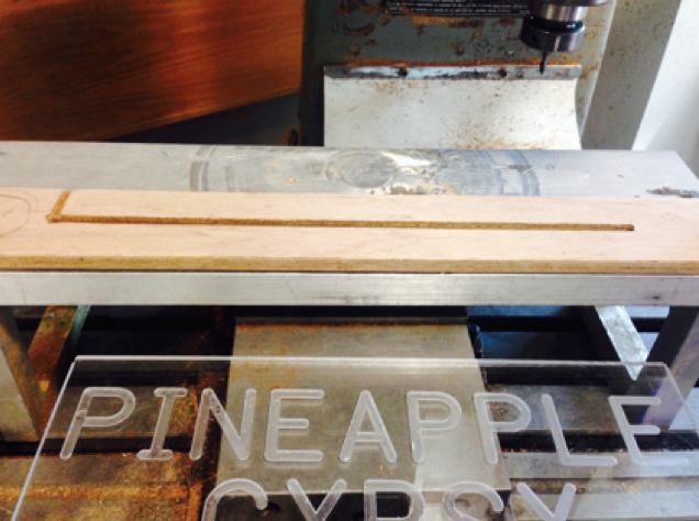
-
Measure the surface of the z-axis and zero it out in the Datum.
-
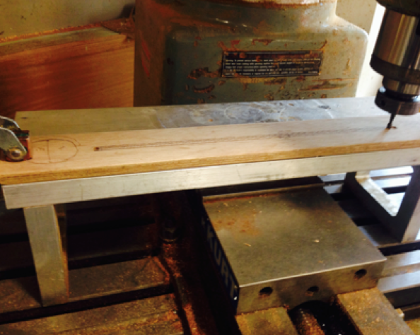
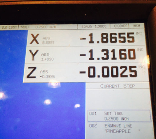
After laying out the slot needed to hold the LED sign upright, use a chuck rather than a collet with a drill bit to drill two 3/8" holes on either edge of your slot. The depths should be around -0.25" to -0.30", which can be read on the monitor of the screen under the z-axis. This will allow the end mill to safely mill through the wooden surface without having to plunge on its own. Even though wood is soft its best to take the right safety and finish precautions.
-
After, use a 3/8” ball end mill (since the acrylic is a 1/4”) so that the sign has enough wiggle room to rest at a slight angle.
-
Since wood is soft enough to prevent the risk of breaking the end mill, larger passing depths can be obtained. We can then use -0.1” as a depth interval for each pass.
-
Slowly progress to -0.25” or -0.30“ below the surface along the z-axis (about 2-3 passes).
-
At one of the ends create an incision perpendicular to that of your slot. This will be the canal in which we feed the wires from the LED strip to the power supply through (refer to the picture above).
-
You could also personalize the stand with more engravings or even pockets on either side to the hold 3D printed objects. Due to the obscene length of this tutorial I will not be posting instructions on how to create pockets using the mill, but if people are interested I can at a later time! Just let me know!
Finishing the Mount
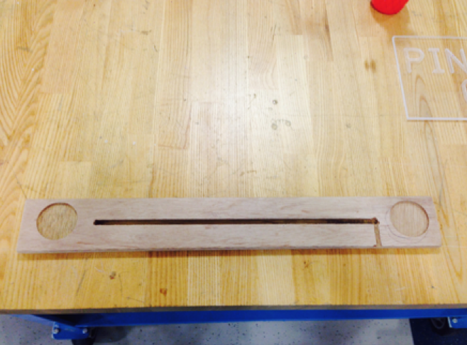
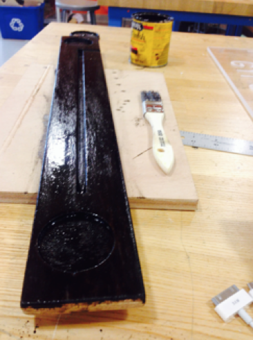
- When finishing a piece of wood, make sure to sand the entire piece down along the grain so that the finish will better catch to the grains of the wood. Also make sure to sand within the pockets/slots.
- Once you have finished sanding and dusting away the debris, apply a coat of finish onto the mount.
- Remember to read the instructions before using the finish! I like to use a rag when applying finish since it allows for complete and even coats. Make sure to apply the finish along the grain of the wood.
- Sometimes if there are splotches from the finish, wipe off the excess finish, allow the piece to dry and begin sanding that area or the entire surface of the mount again. Wipe off the dust and apply a new, even coat.
- Allow the finish to set for 15 minutes and then wipe off the excess using a clean rag. Continue to repeat this process on all sides of the mount and within the pockets/slots until you are satisfied with the color. A darker finish is achieved after applying several coats to the mount. Place the same amount of pressure and finish along the surface of the mount to allow for an even coat.
- Allow this to dry for roughly a day.
Soldering the RGBs to the Power Barrel Connector Part I
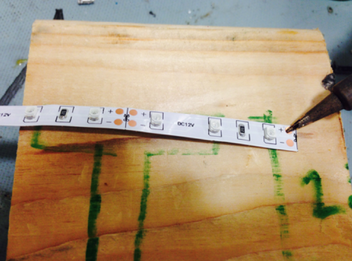
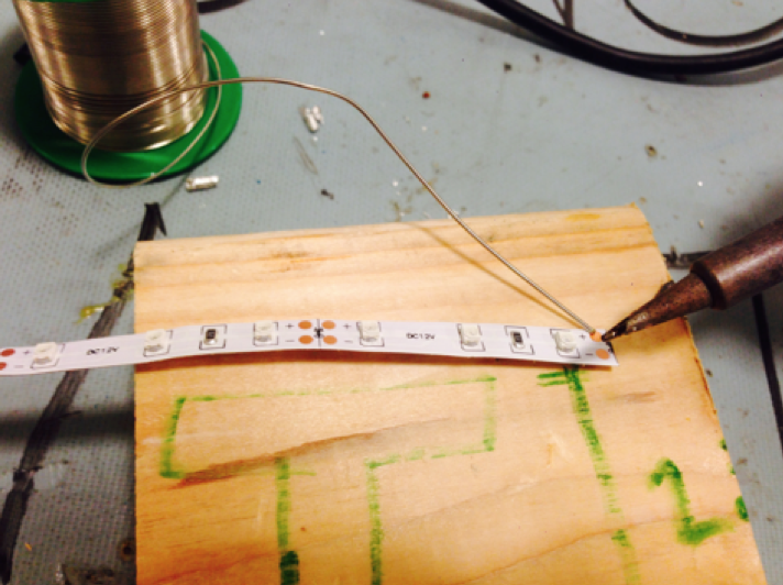
- Begin by cutting a strip of RGBs to the desired length (must be shorter than the length of the slot).
- After turning the soldering iron on, apply a small amount of solder to the tip of the soldering iron. This will allow the solder to melt quicker when applying it to various parts of the circuit.
- Place the tip of soldering iron on the copper terminals. A silver blob should be created. Try to keep the solder in the copper terminals.
- Once the positive terminal cools, repeat this process for the negative side: Melt solder onto the tip of the soldering iron again and repeat this on the next terminal.
Soldering the RGBs to the Power Barrel Connector Part II
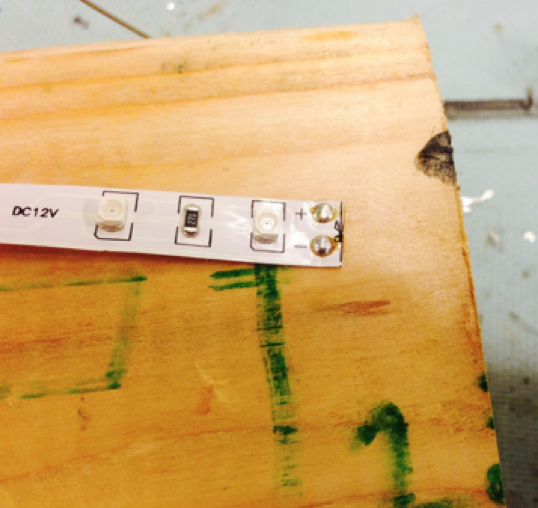
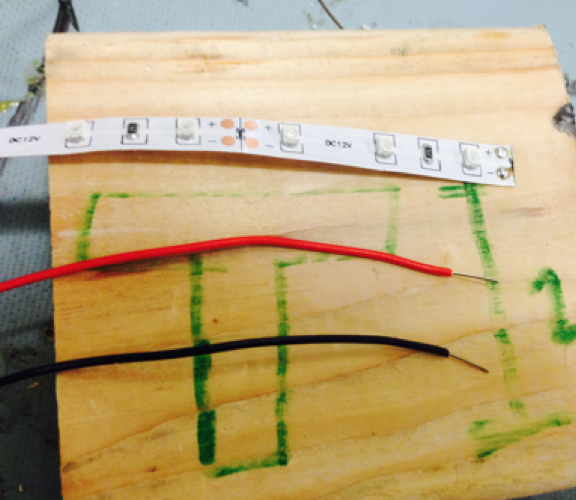
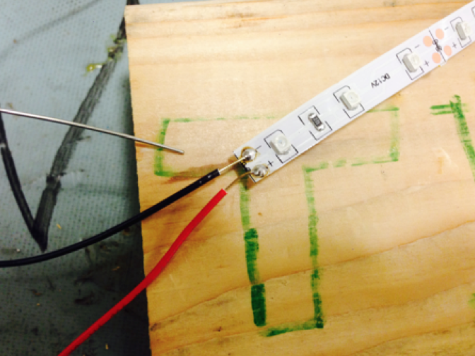
- Cut two wires (red and black 28 AWG wires) using wire cutters.
- Use a wire stripper or scissors to strip off around 1/2" of insulation from either ends of the wires.
- Once both terminals have been soldered (make sure the solder from both terminals do not touch each other or else the RGBs will short circuit!!!!!), apply solder onto the edge of the soldering iron and transfer it to the tip of each wire used for the circuit.
- After, align the black wire with the negative terminal and sandwich the wire beneath the soldering iron onto the copper terminal (make sure the tip of the iron has been coated with solder).
- Heat up the solder until it melt enough over and around the end of the wire. Allow it to cool.
- Repeat this for the positive lead.
Soldering the RGBs to the Power Barrel Connector Part III
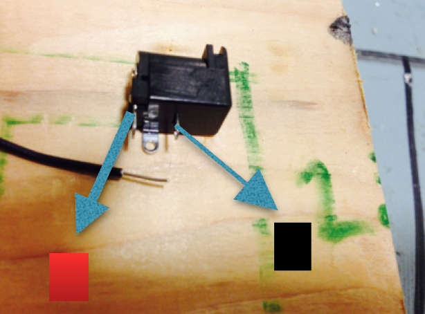
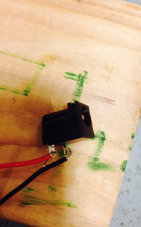
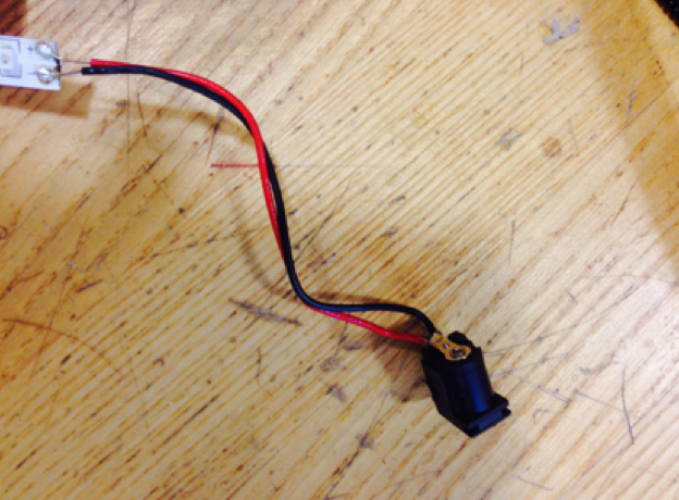
- Now connect the barrel connector to the other end of the wires using a similar process used above. After coating the soldering iron tip and the the tip of the wire with solder, we can easily curve the wire around the barrel connector’s terminals for a clean attachment.
- The barrel connector’s terminals are labeled in the picture, red is positive, black is negative.
- The middle pin between both the positive and the negative terminals is electrically insulated and is typically used to create a better attachment when soldering to circuit boards.
- Once wrapped, heat each pin first and then apply a generous amount of solder. Again, make sure that the solder does not touch both leads!
- Once you are finished, turn off the soldering iron and allow the barrel connector to cool.
Connecting the RGBs to the Mount

- Once done with soldering, peel the paper off from the back of the RGBs and stick the adhesive side to the bottom of the slot located within the mount.
- Afterwards, loop the wires through the L slot until the barrel connector is hanging off of the side of the mount as featured above.
Adding More Aesthetics
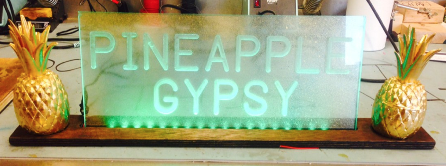
- If you are interested in creating more aesthetic appeal for your sign, spray paint the back of the sign with various colors. Make sure to not over do it, we still want a transparent appeal.
- Place the 3D objects on either side of the mount. Apply adhesive material such as epoxy or super glue if you would like to keep them in place.
Now attach this to a 12V, 1A power supply and you are done! Give this to someone you think is awesome or keep it for yourself!