LED Matrix PCB (Full Beginner Tutorial)
by ICARUS in Circuits > Electronics
4498 Views, 26 Favorites, 0 Comments
LED Matrix PCB (Full Beginner Tutorial)
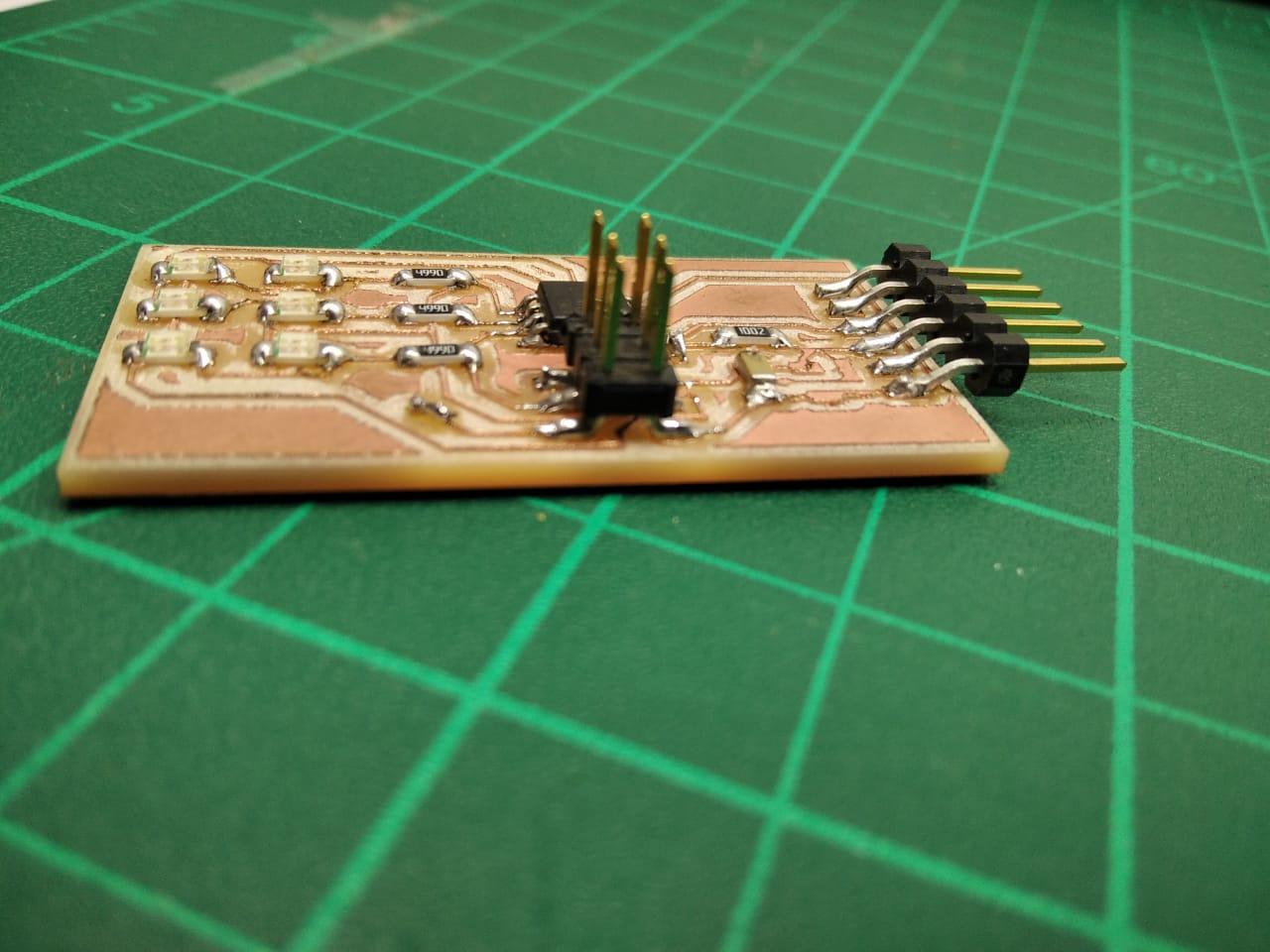
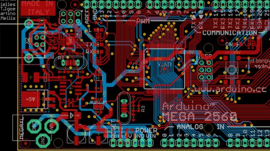
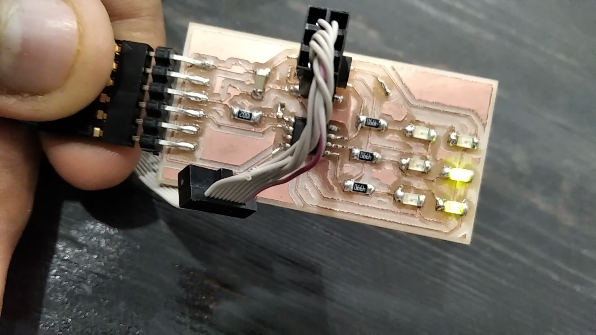
What is PCB design software?
__________________________________________
PCB is a free and open-source software suite for electronic design automation (EDA) - for printed circuit boards (PCB) layouts. It uses GTK+ for its GUI widgets.
5 best PCB design software for 2023
_____________________________________________
Ansys RedHawk.
Fusion 360.
Altium CircuitMaker.
Autodesk EAGLE.
SOLIDWORKS.
What is Eagle PCB software?
__________________________________________
EAGLE is a scriptable electronic design automation (EDA) application with schematic capture, printed circuit board (PCB) layout, auto-router, and computer-aided manufacturing (CAM) features.
What are nets in PCB design?
__________________________________________
A PCB design tool represents the necessary connections between parts with a wire. These wires are called nets.
What is PCB routing?
______________________________________________
In electronic design, wire routing, commonly called simply routing, is a step in the design of printed circuit boards (PCBs) and integrated circuits (ICs).
It builds on a preceding step, called placement, which determines the location of each active element of an IC or component on a PCB.
Supplies



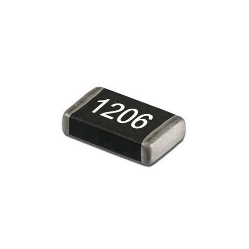
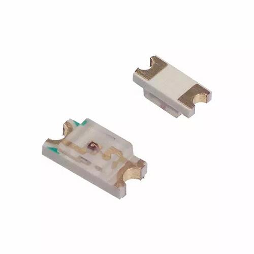
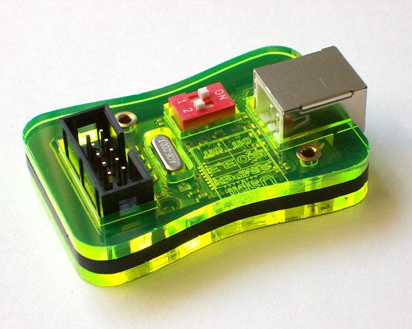
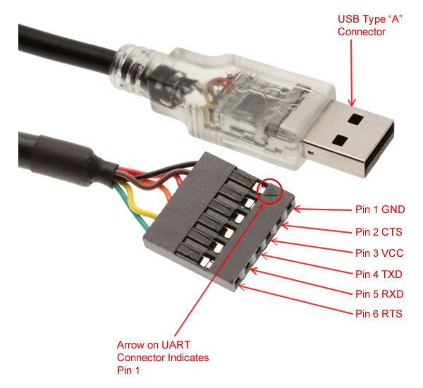
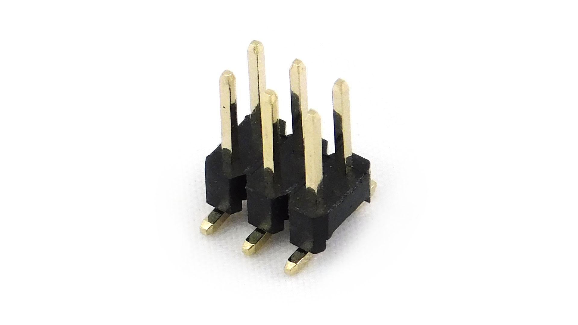
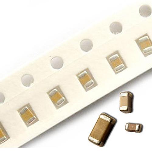
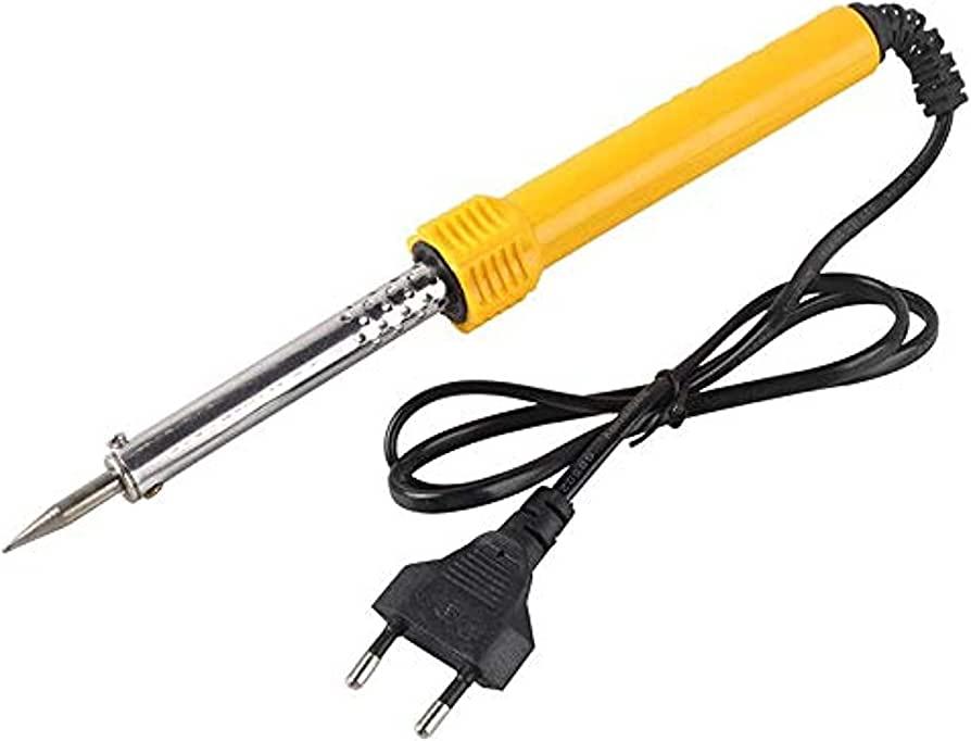
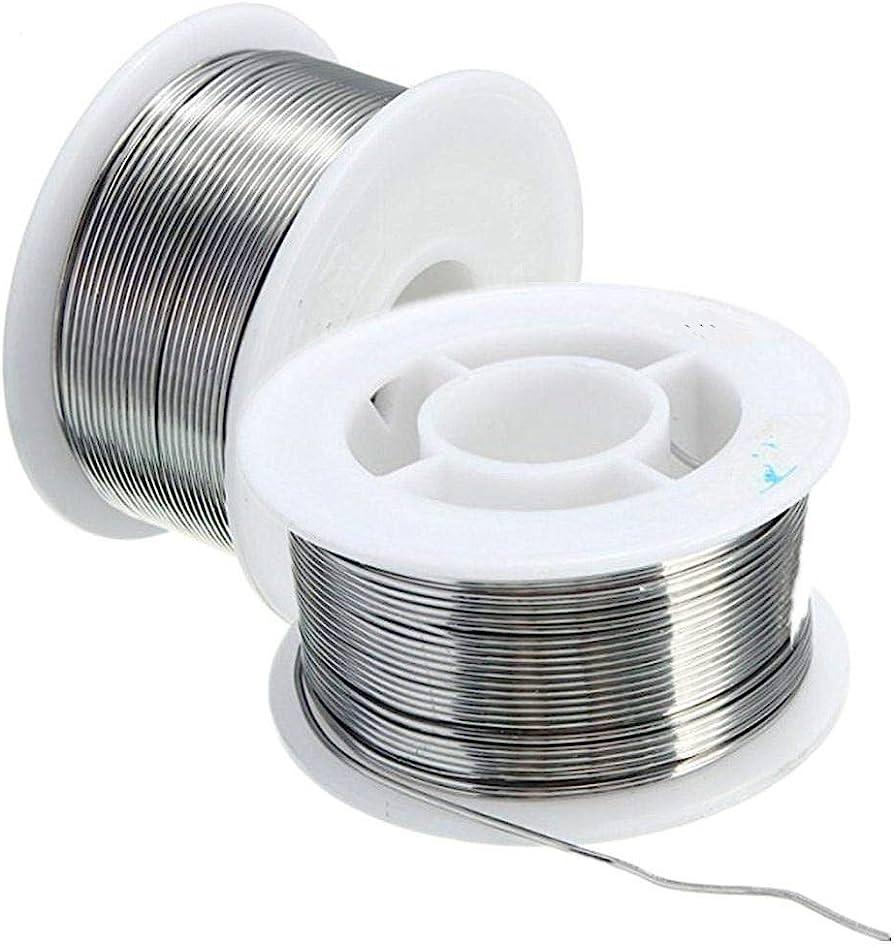

What we need to make this PCB
Softwares
- Eagle Cad
- Gimp
- fusion 360 (optional To preview the PCB)
Components
- 6 LED SMD (1206)
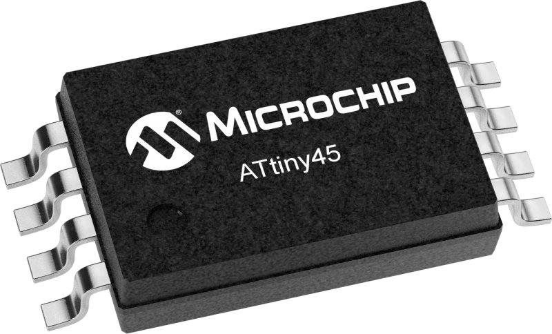
- ATTINY 45
- ISP Header 2x3
- FTDI Header & FTDI programmer
- Capacitor 0.1uf & 1uf (1206)
- Resisrors 10K & 499 ohm (12060
- ATMEL ISP
Soldering stuff
- Soldering iron.
- Solder.
- flux.
For Machine
- Setting up the copper board.
- Fixing the copper board to a wood sacrificial layer.
- 1/64” endmill with 1/32” endmill.
Getting Start With Eagle

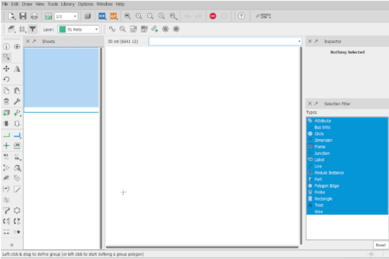
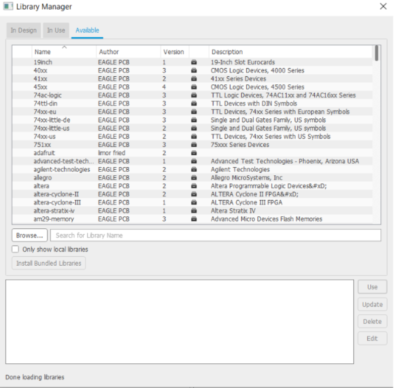
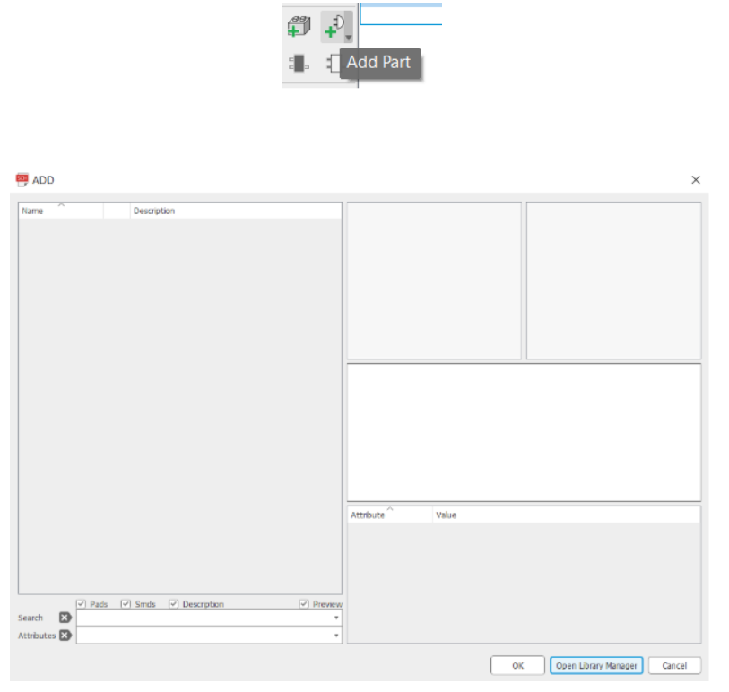
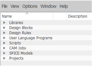
Installing Eagle
In order to design both the schematic and PCB layout of the board I used EAGLE software.
which can be downloaded from
if you have an AUTODESK student account.
After installation was complete I added a new schematic file. A schematic is a drawing representing connections between electronic components.
Then you should add the components you need to use in my board, so I downloaded fab.lbr library.
Then from the Library bar, select Open library manager and browse the location of the downloaded library then it will be automatically added to the component list.
Using Eagle
Eagle is a simple software, you wouldn't need much to learn it, However, what you need is to practice on it, over and over to become a master of it.
You can see this video to see how to make a PCB layout Youtube
___________________________________________________________________________
First-time users of EAGLE will be greeted with the rather confusing Eagle Control Panel. You probably expected to see a direct-to-schematic approach, but no, this isn’t a very beginner-friendly application (but it’s very rewarding indeed, so stay tuned)
Start by going to File>New>Project. A new project should appear. You can give it a name, but I chose not to.
Now go to File>New>Schematic. This will create a new schematic in the project that was currently open.
You will be greeted with another less-than-intuitive window where there is seemingly no way to start drawing a schematic.
You may have clicked the Add Part tool, only to be greeted by a window that shows no components to be added, and probably tried another way, as I did when I first started learning.
In earlier versions, this was more complicated but now you only need to click the Open Library Manager button and go to the Available tab.
You may choose to download all the available libraries, but if you aren’t keen on waiting for 412 (as of May 2019) libraries to download, I recommend searching for the libraries by SparkFun as well as the libraries rcl, linear, transistor-fet, transistor-npn, transistor-pnp, and transistor-power, all in lbr format.
The libraries by SparkFun are easily the most useful libraries for fiddling with Arduino, Raspberry Pi, smart home systems, and most hobby electronics involving microcontrollers.
Information About PCB Fabrication
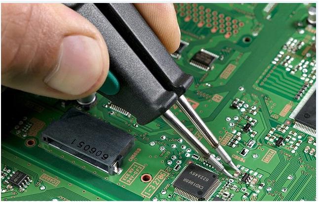
Knowing what PCB fabrication is
____________________________________________
Printed circuit boards are used in all gadgets of recent times and in order to fulfill the proper function of instruments all the different electrical and electronic parts are fixed organized and fixed together. This whole process of organizing is called PCB assembly or PCB fabrication. During the PCB fabrication process, Great PCB SMT Limited makes sure that proper mechanical support and electrical conductivity to the printed circuit board have been ensured. It is mandatory to perform this step in order to make sure that the best performance of the electronic and electrical modules is imprinted on the conductive etches that are on the surface of the printed circuit boards. If you want to acquire the top quality batch of PCBs then hiring the most proficient company would be the best thing to do.
Understanding the importance
________________________________________________
Whichever sort of computation a machine is based on it will need a PCB in its core. The regular instruments which we use on a daily basis, such as a digital watch, operate through a printed circuit board that controls its function. Manufacturing of a PCB is a process that includes several steps and to ensure an error-free PCB assembly process, seeking and including a professional manufacturing company is necessary. The central steps of manufacturing that one needs to be aware of are given below.
Drilling and soldering
______________________________________________
After piercing the board is plated with copper to coat the exterior of the PCB. Then a soldering mask is used to cover the board and then comes the computerized scrutiny.
Announcement
________________________________________
I recommend if you want to make a PCB you can make it at Seeed Studio
Seeed Studio Fusion PCBA Service,
available at https://www.seeedstudio.com/fusion.html, offers comprehensive PCB manufacturing, prototype PCB assembly, and more. Their services cover everything from PCB fabrication, parts sourcing, and assembly, to testing, ensuring top-notch quality throughout the process. Furthermore, once you've gauged market interest and validated your prototype, Seeed Propagate Service can assist you in bringing your product to market with expert guidance and a well-established network of connections.
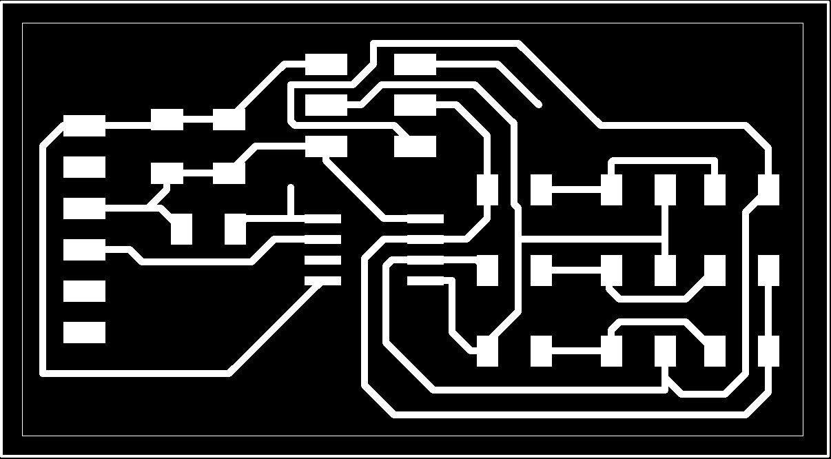
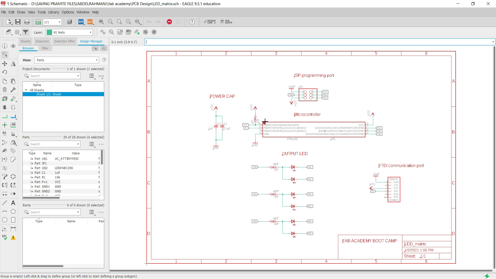
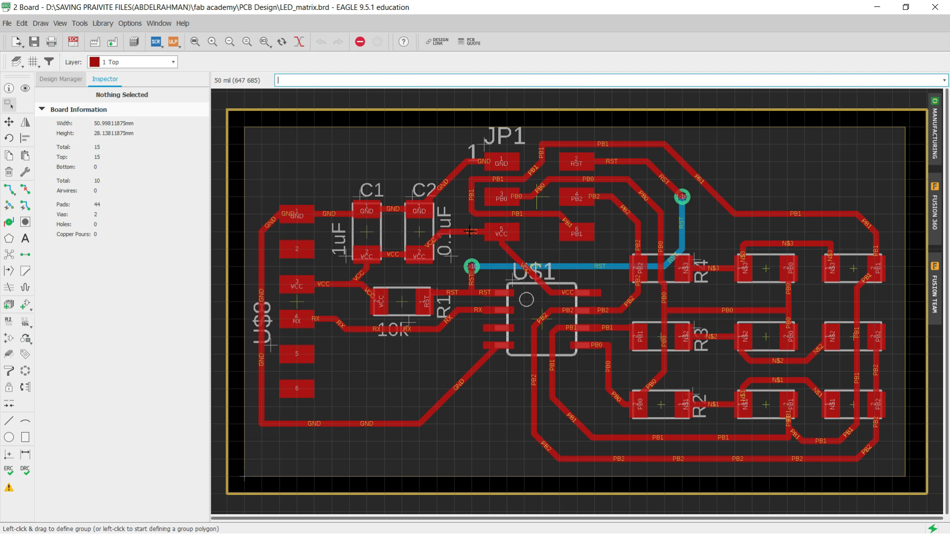
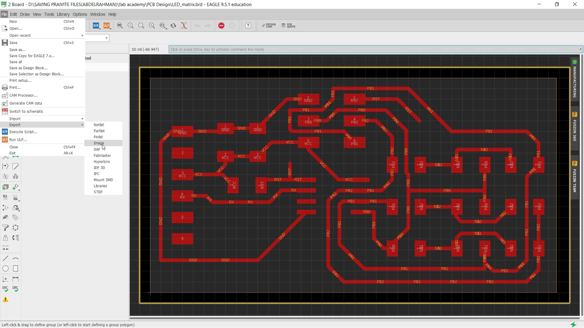
We have designed the PCB on Autodesk Eagle which includes the essential components to
Make this board work. The PCB includes an embedded microcontroller, a programming port, to upload your code on the microcontroller, 6 LEDs and their resistors, and finally FTDI port to
communicate with the PC later on. Install Autodesk Eagle and open the .sch and .brd files
attached to this guide and take a look at the designs
You can download the schematic and board
STEPS
- Open the schematic file and understand how the PCB should work
- Open the Board file of the LED Matrix
- Choose file >> Export >> Image
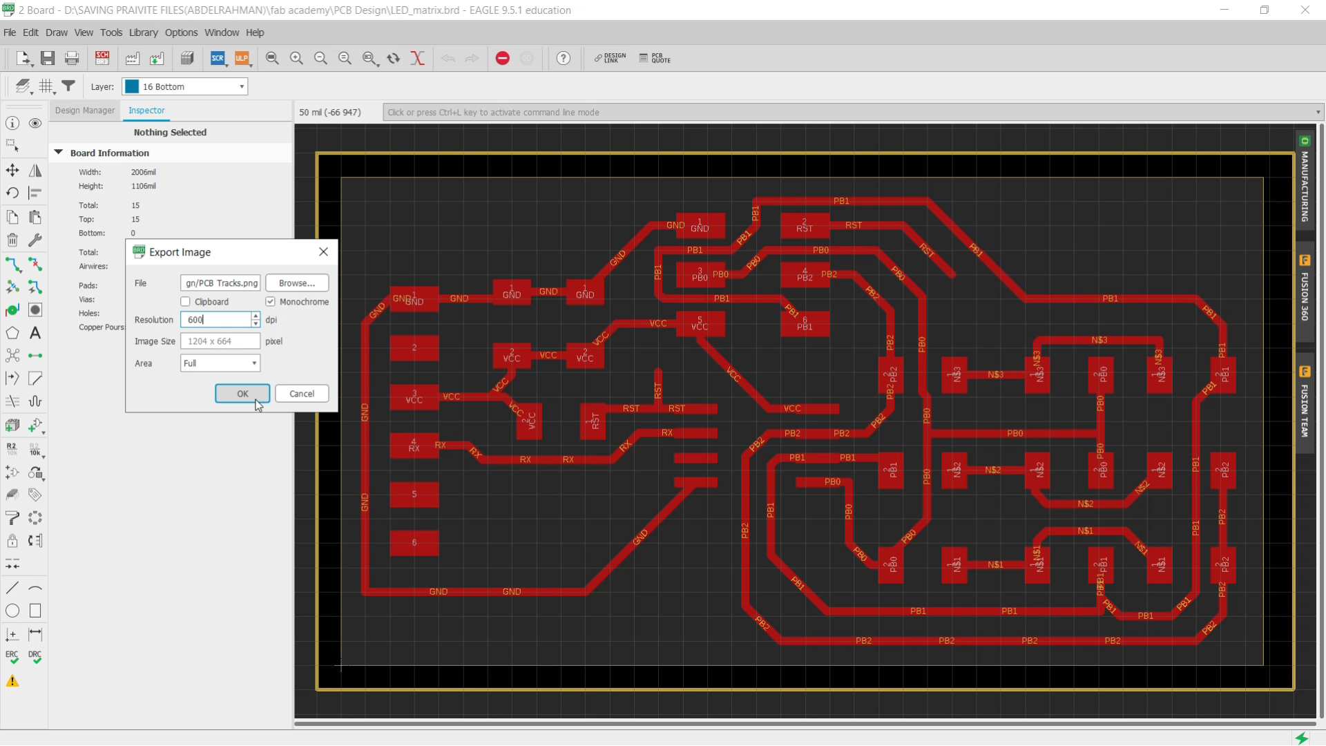
- Choose where you will Locate your files then choose (monochrome) and adjust the resolution to 600 dpi
You should choose the Top layer and the dimention layer At frist and then repeat this process for the Via
Downloads
Imagine the PCB
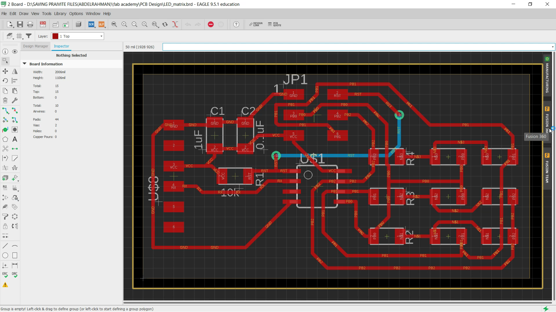
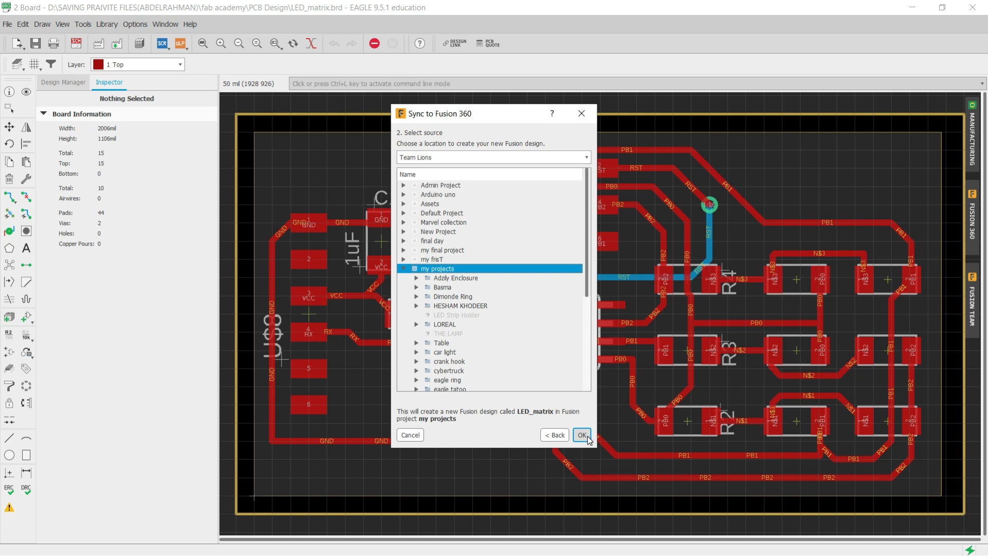
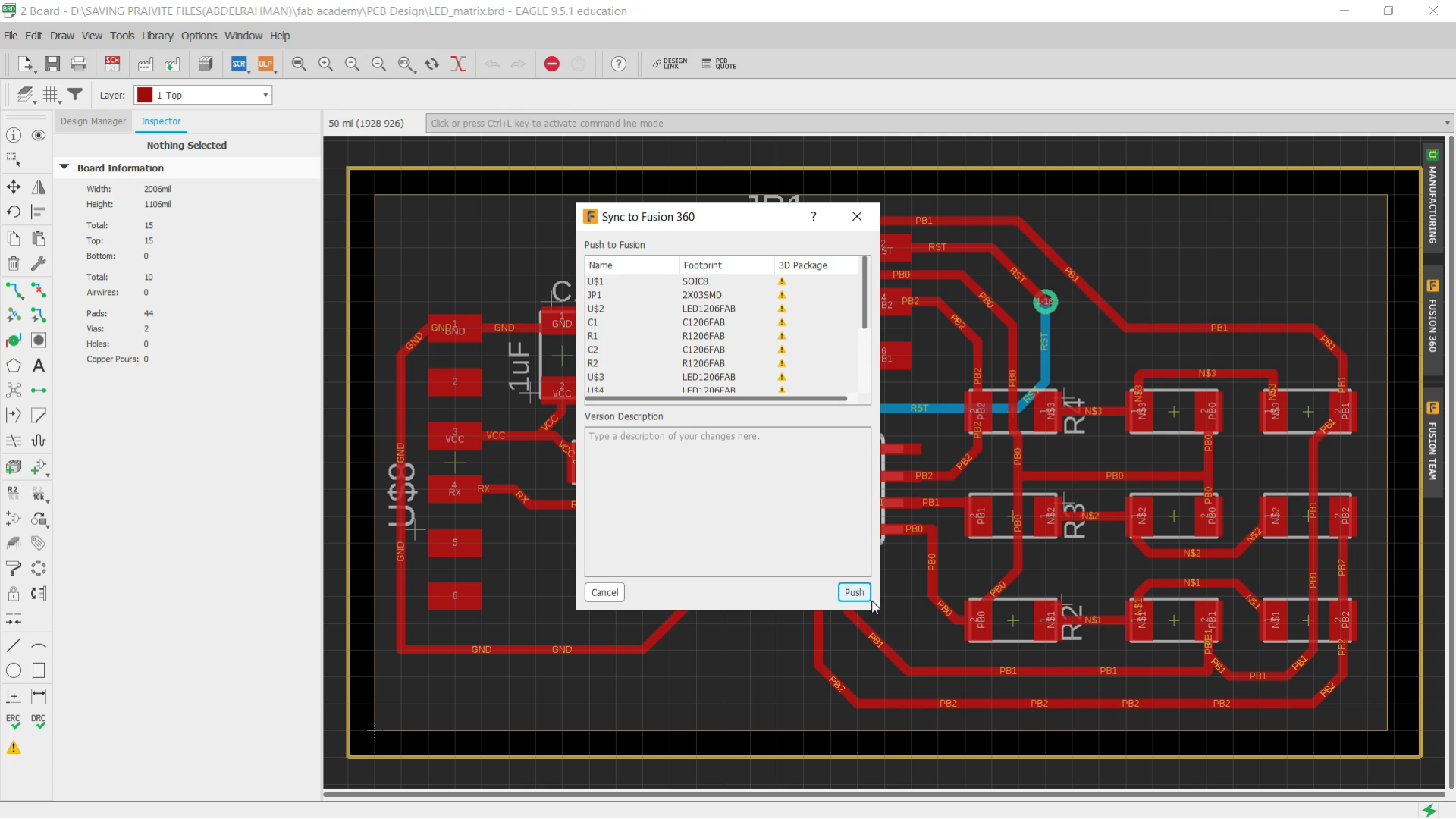
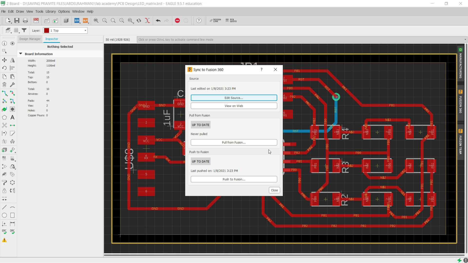
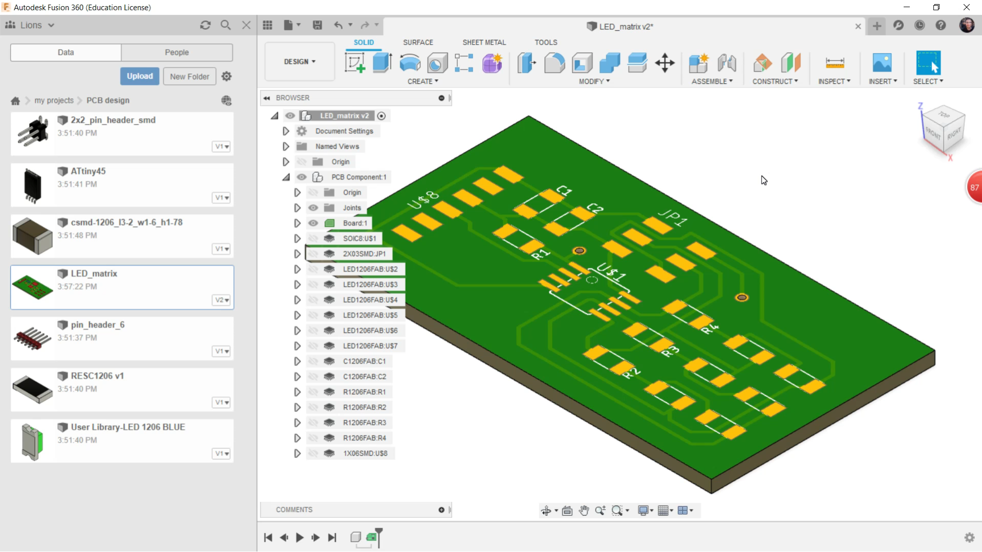
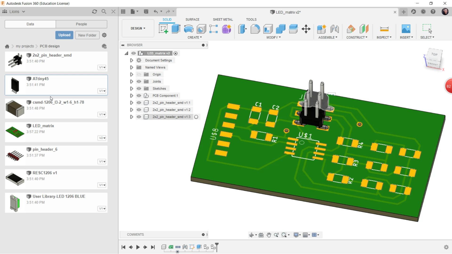
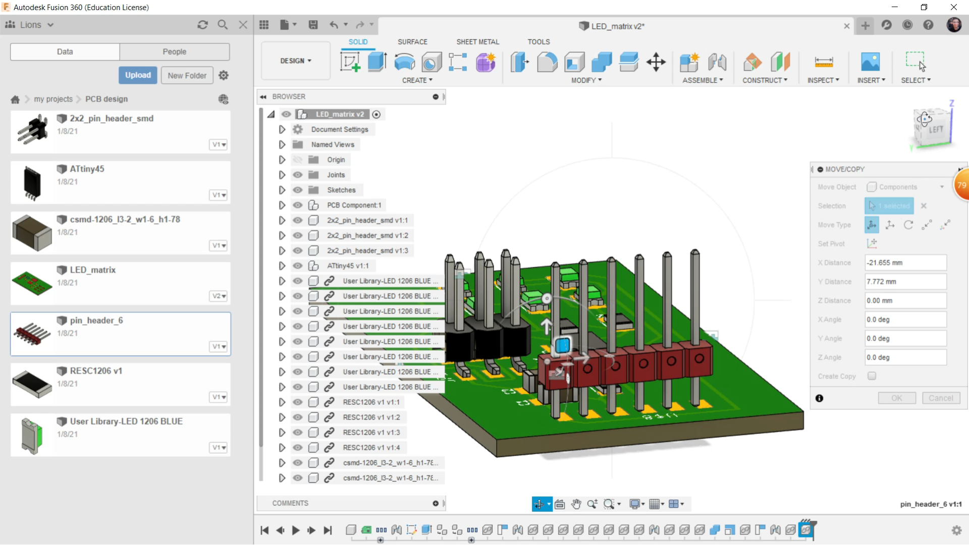
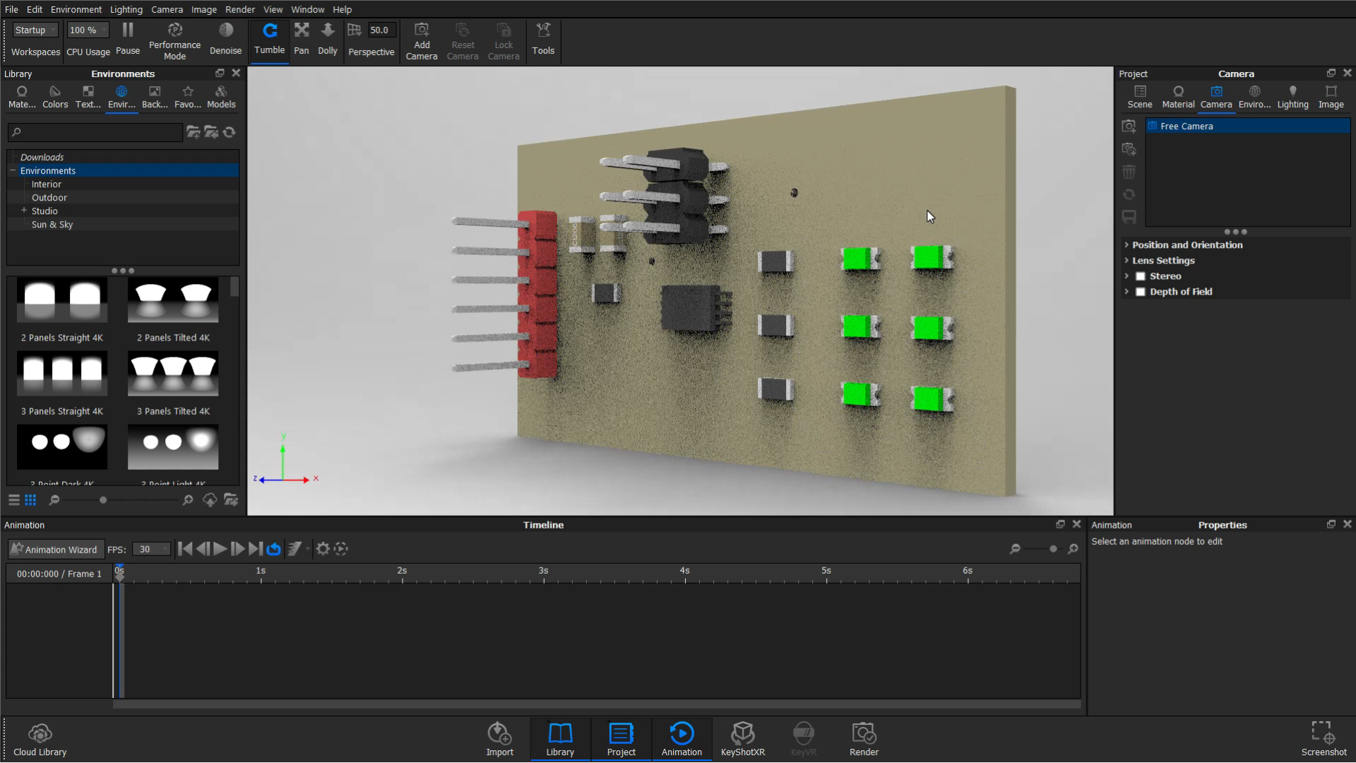
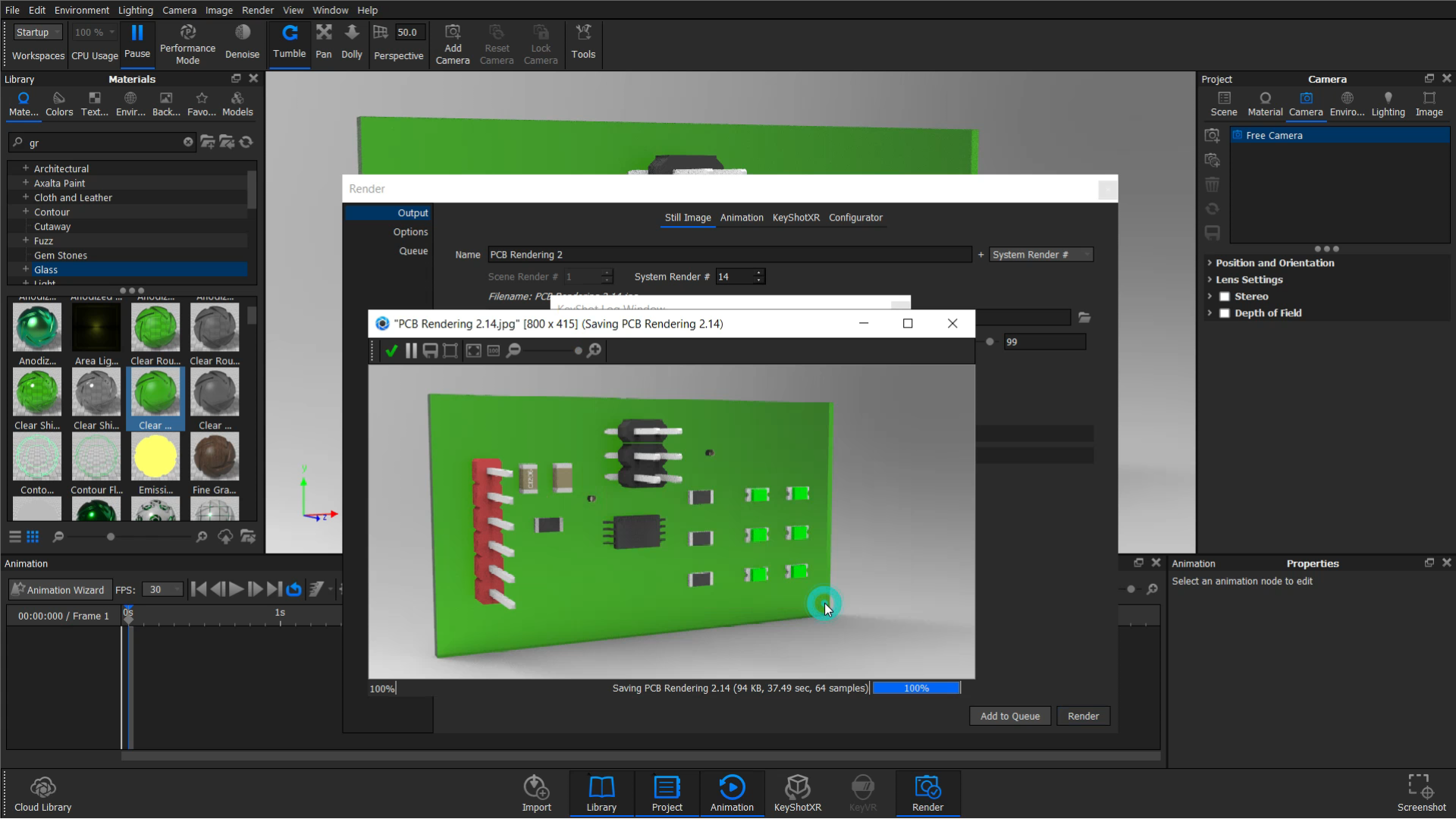
The following steps are not essential, However, It will give you a visualization of how the PCB should Look Like
It's a nice skill to know, Anyway Let's Begin
Note
You should have Fusion 360 with the same acount of Eagle To send the files from Eagle to Fusion
Steps
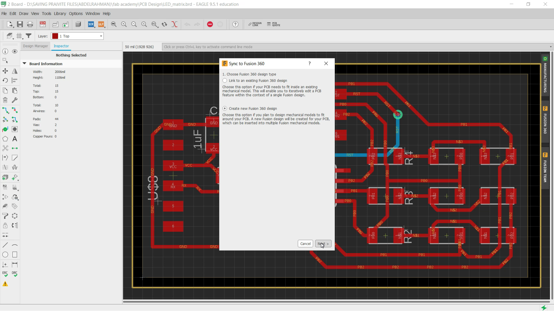
- Open the Board file on eagle And choose Fusion 360 From the Right side
- Choose "Create new fusion 360 design " and click Next
- Choose where you will Put this PCB
- Push the files to Fusion 360
- wait until it Pushes To Fusion 360
- Open Fusion 360 and Open the PCB
- Start to put the Component on the PCB
- Put all the Compenet in its Footprint Signature
- Now you are Ready to make the Rendering, You can make the Rendering on Fusion Or you can Use Rendering Software Like "Key Shot" All Options are in your Hand
Note
I get the component From Grab CAD and install it with STEP Extention
GrabCad
Let's Fabricate the PCB
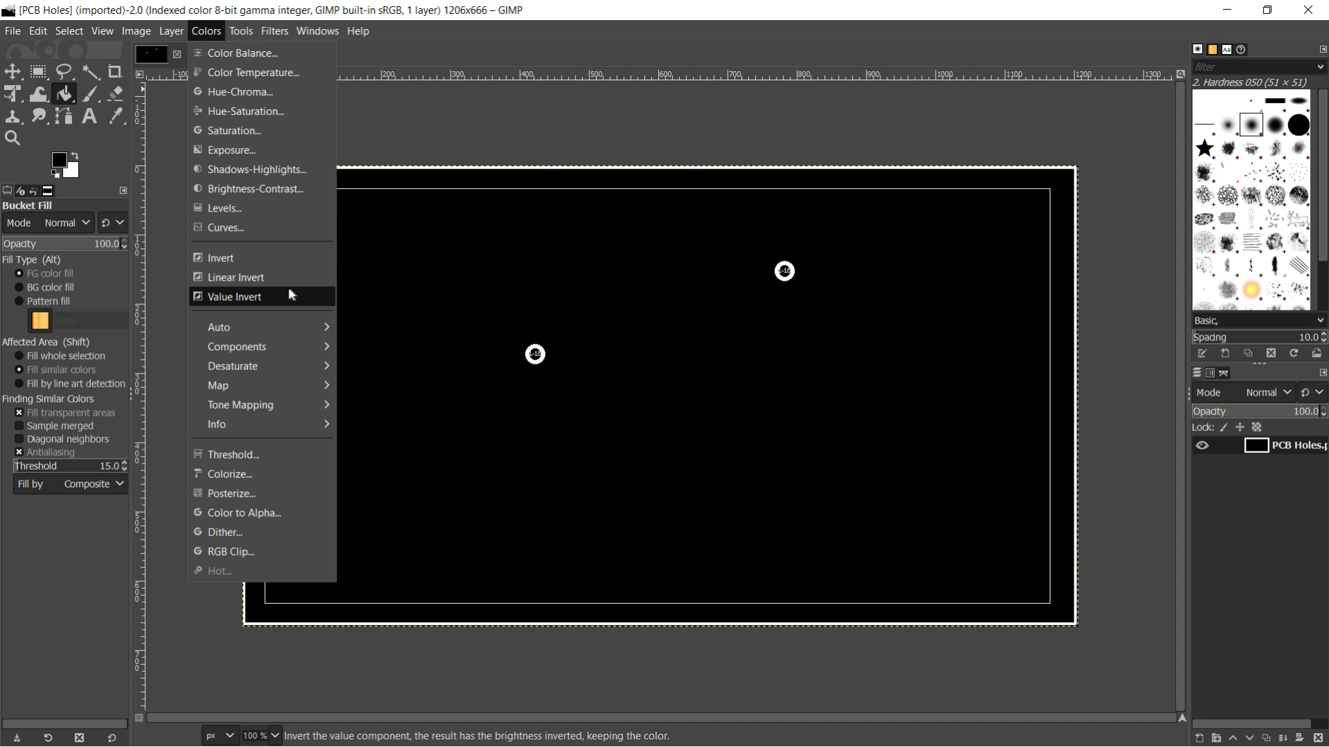
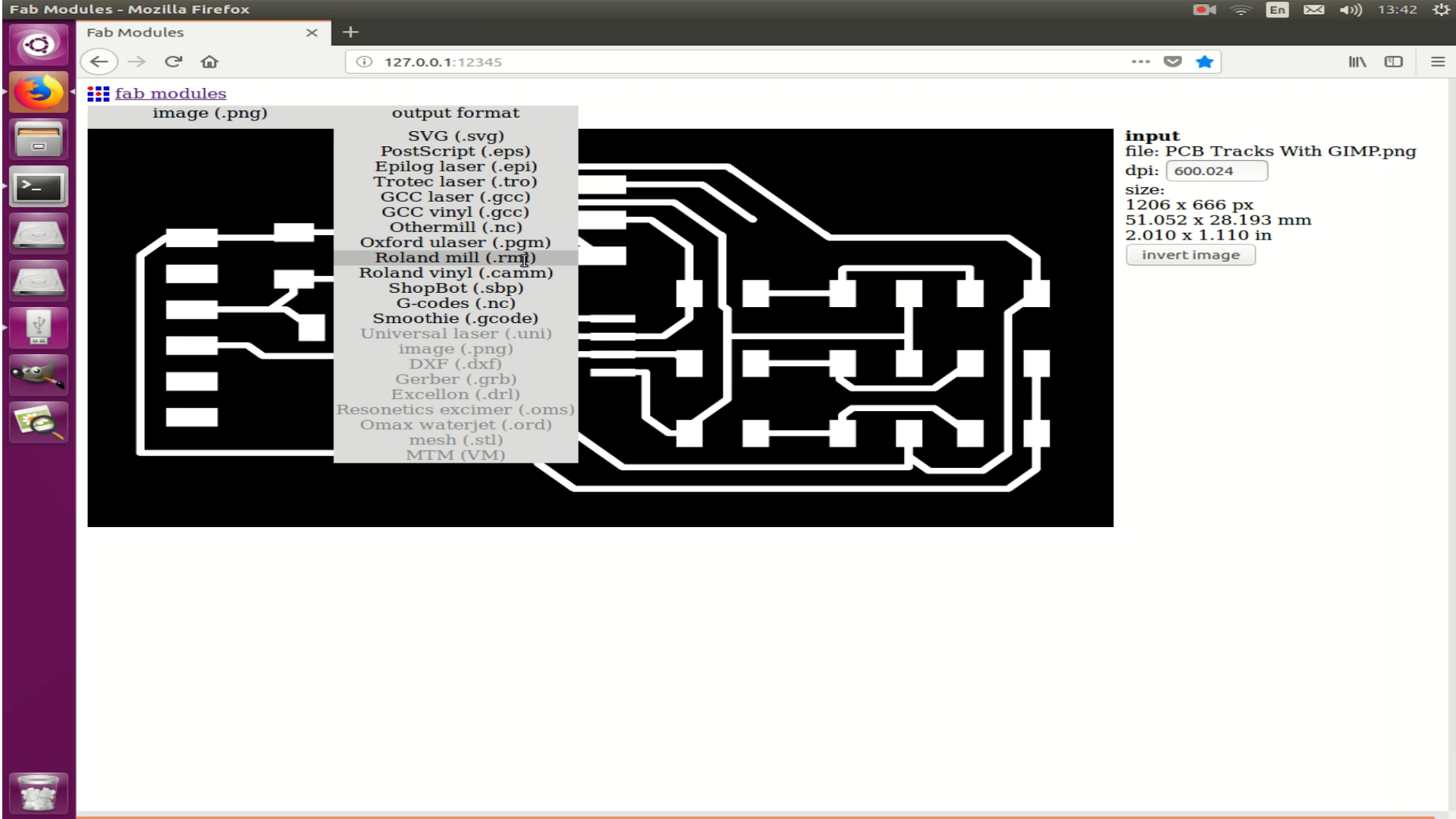
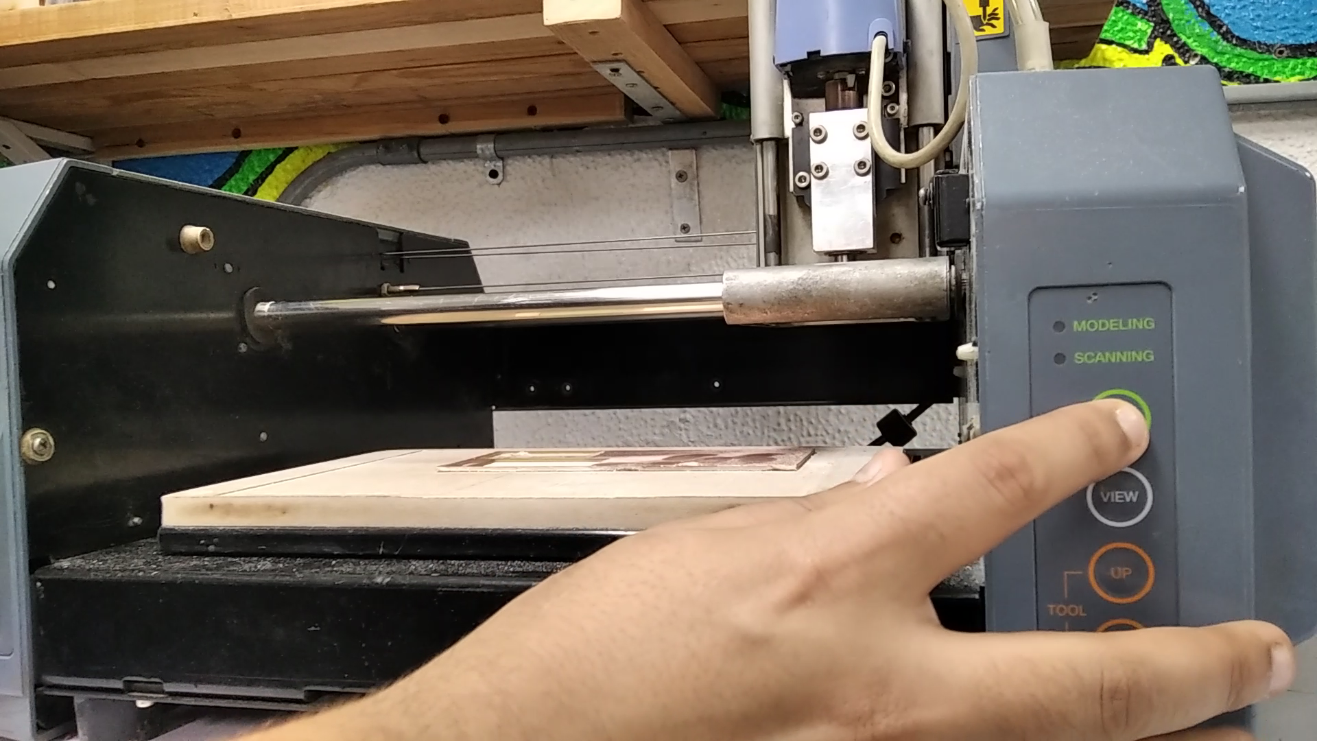
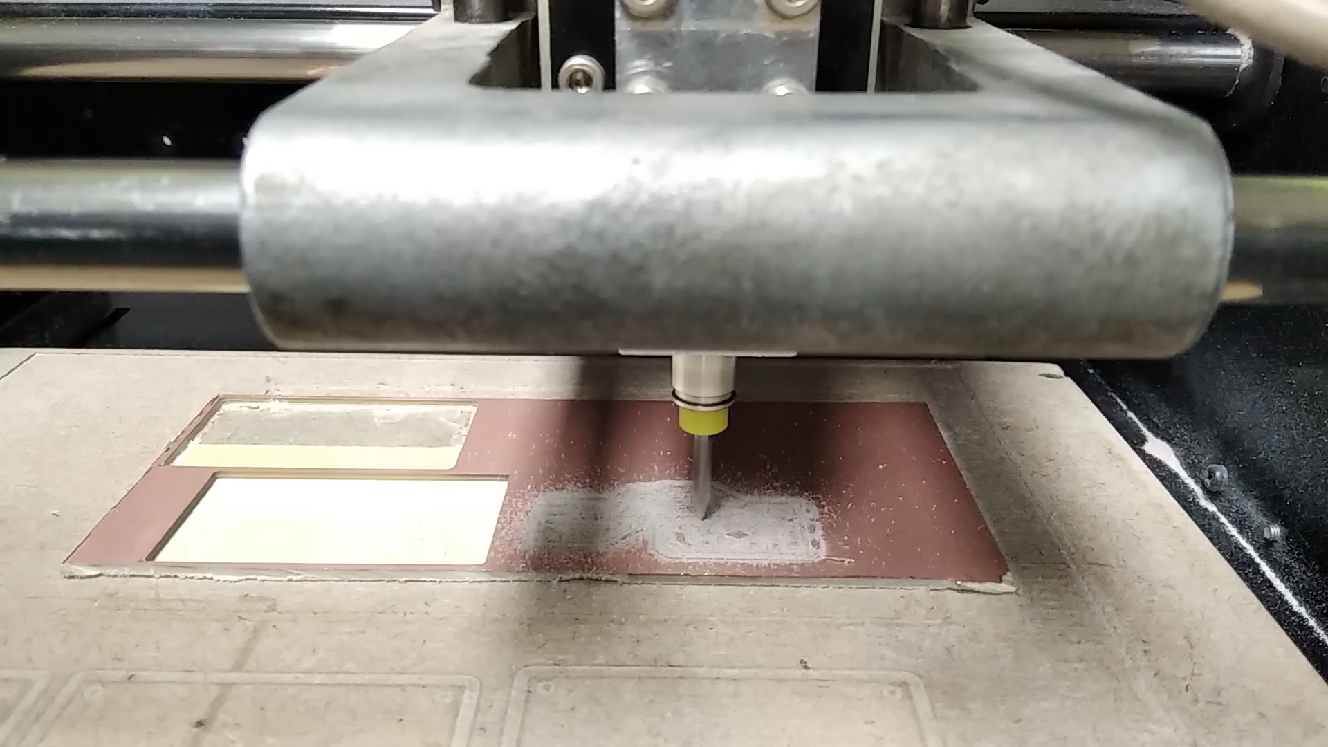
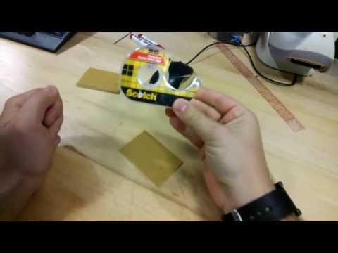
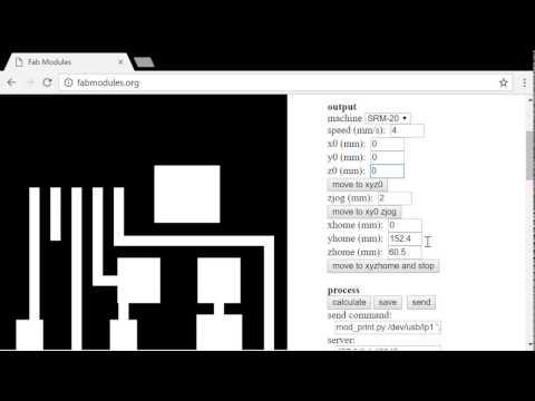
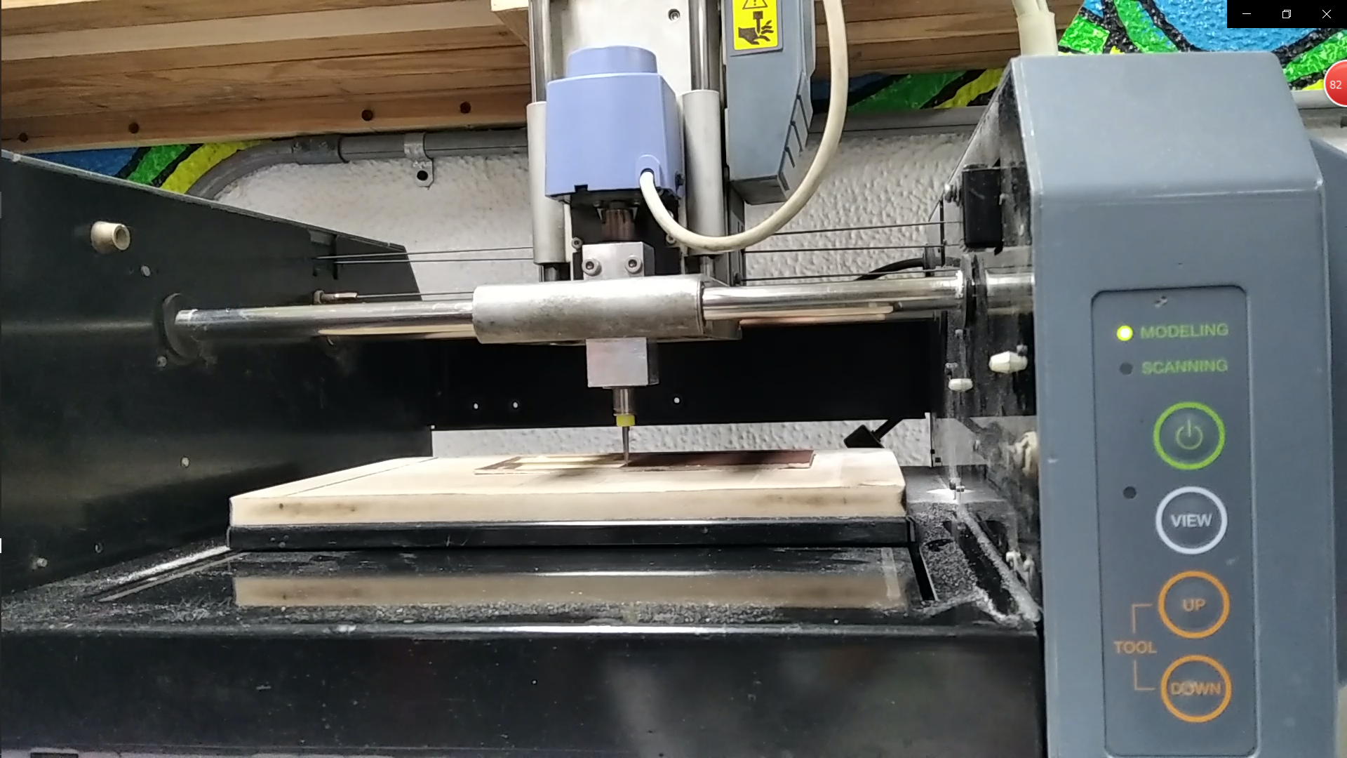
in this part, we will fabricate the PCB using Modela Melling Machine
This part is fun and easy to make just Follow the instructions
Now we get our hands involved! The milling process is done on a large piece of copper and
using two endmills: 1/64 for milling the traces and 1/32 for cutting the board. The steps you
need to follow are as follows:
___________________________________
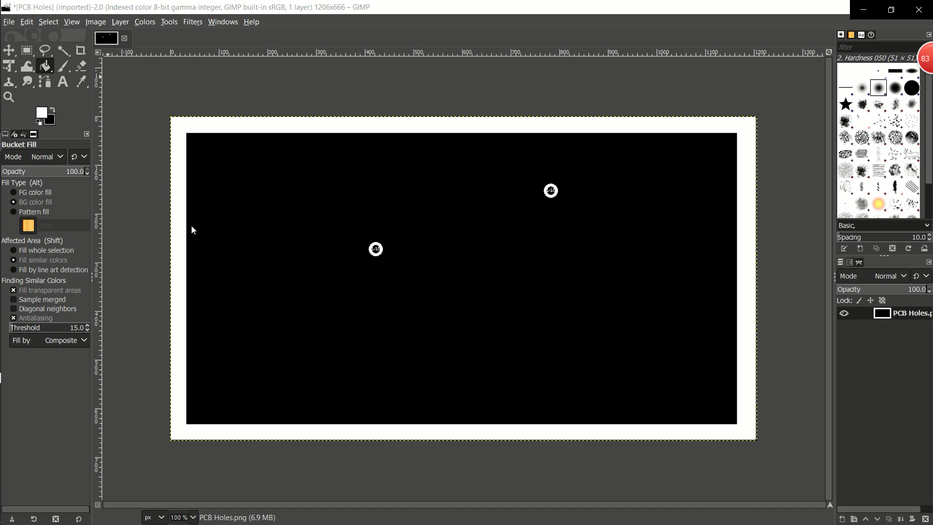
- Open the Holes Photos and invert the colors on Gimp
- Setting up the copper board.
- Fixing the copper board to a wood sacrificial layer
- Placing the 1/64” endmill.
- Setup the zero point in X, Y, and Z.
- Using Fab modules to generate the toolpath for trace milling using a 1/64” board.
- Send the toolpath to the machine.
- Replace the 1/64” endmill with the 1/32” endmill.
- Setup the zero point in X, Y, and Z.
- Using Fab modules to generate the toolpath for the cutting process.
- Send the toolpath to the machine.
__________________________________
For setting up the machine, I would recommend watching the Following Playlist:
PLAYLIST
Regarding using Fab modules, you would need to learn how to start the local Fab modules
server on the PC. You may ask the lab supervisor how to do that. To generate the toolpath
and send it to the machine, you should follow this video :
FAB MODULES
There are some corrections to the videos
1. Our machine is MDX20.
2. Instead of saving the toolpath, press send to directly execute the toolpath.
3. You may need to put values in the X, and Y fields in case you want to start milling from a
different point other than 0, 0.
Soldering
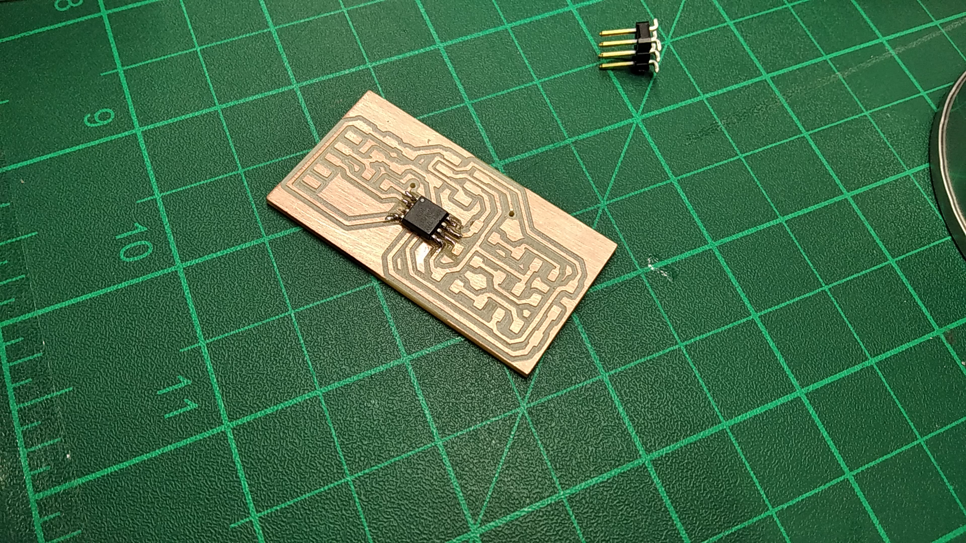
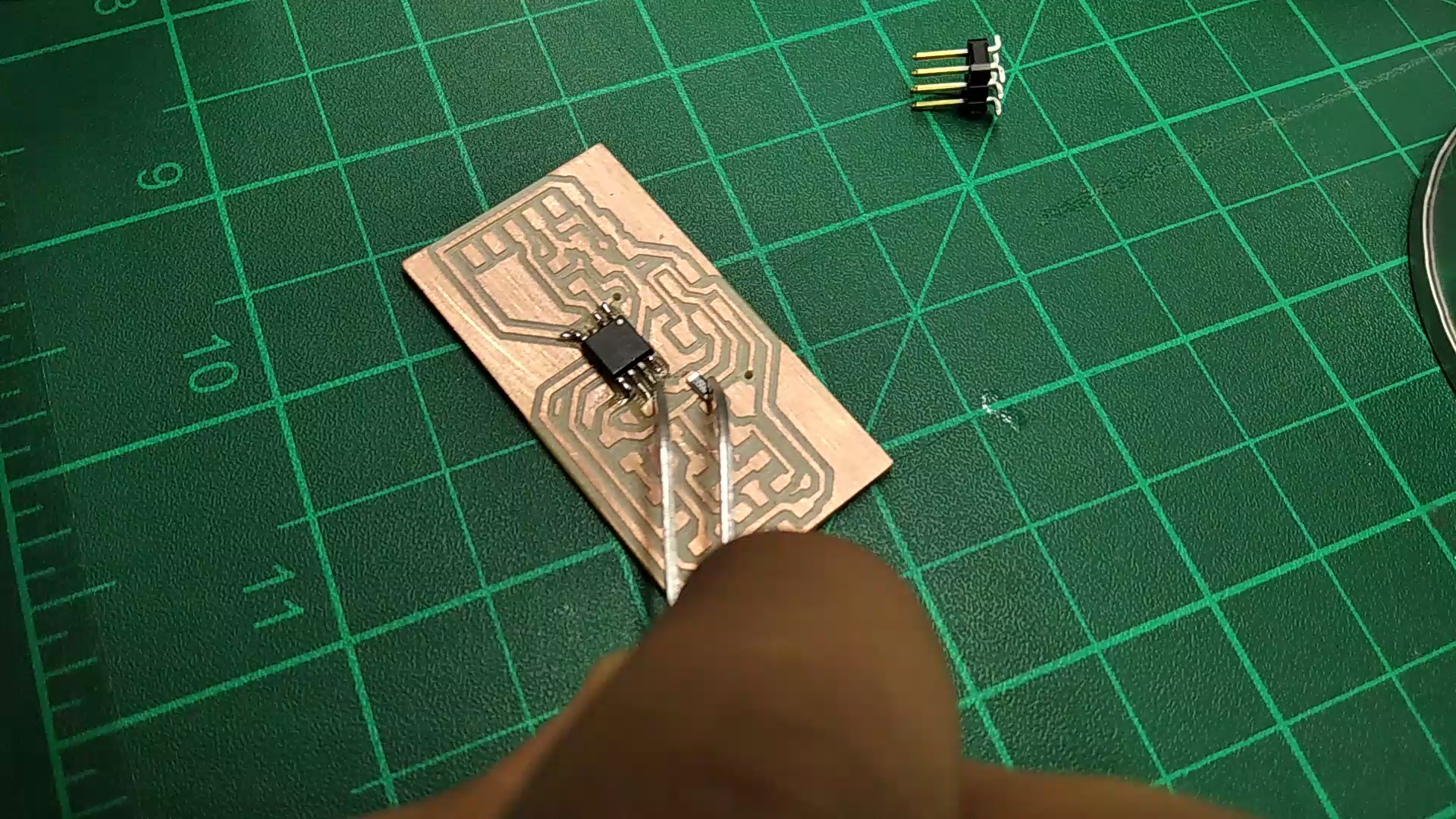
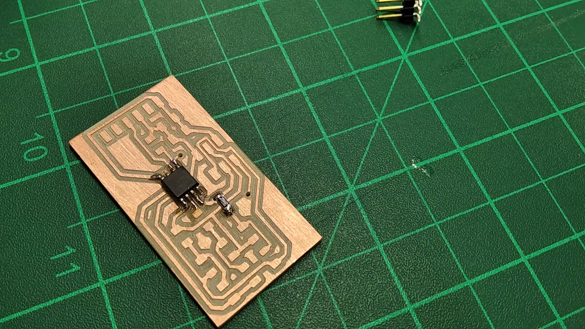
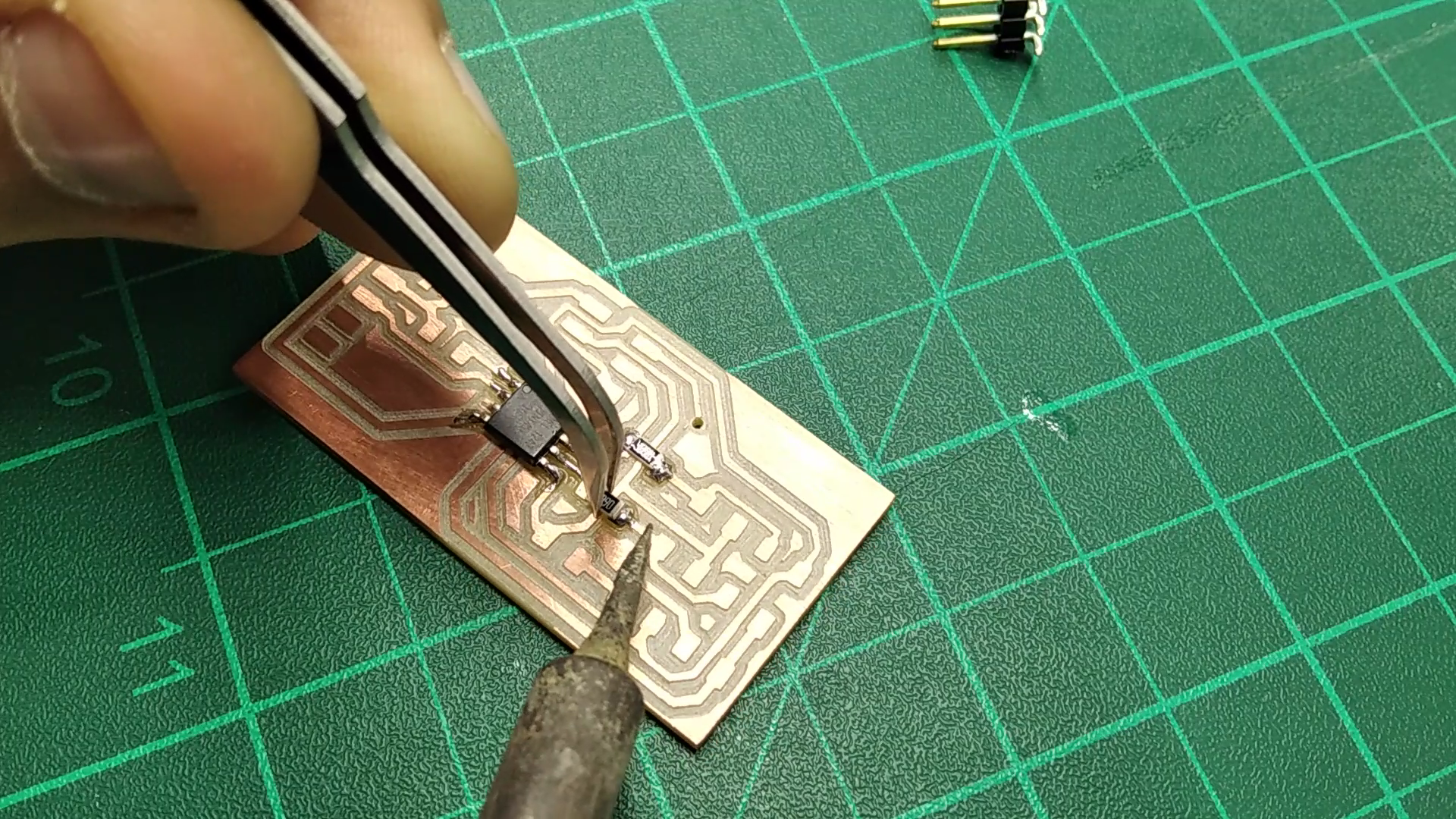
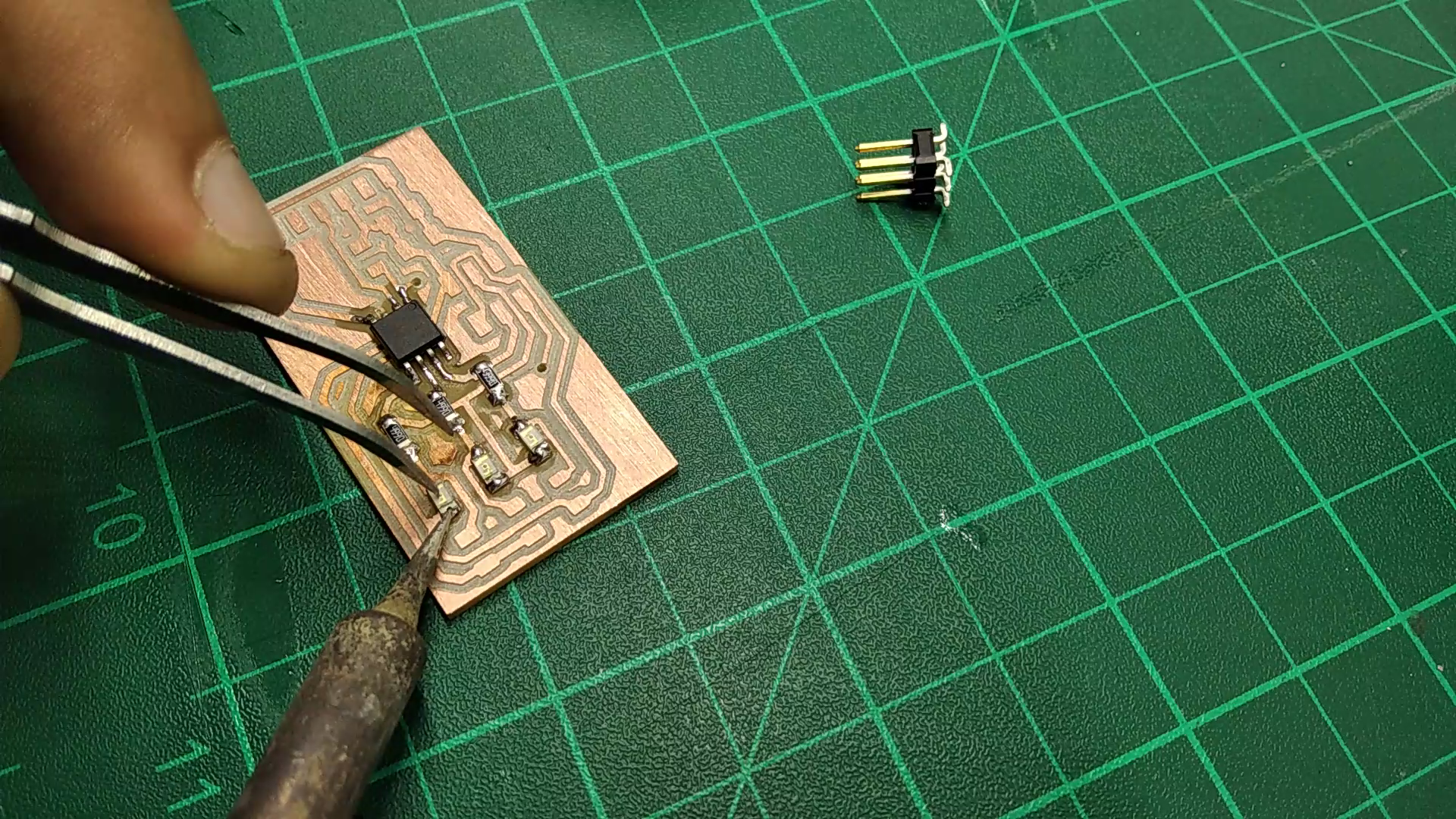
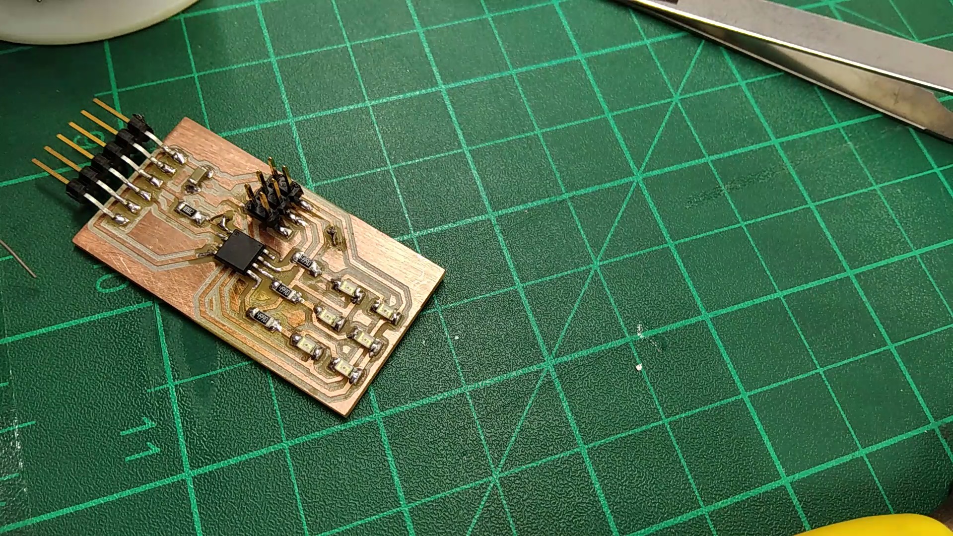
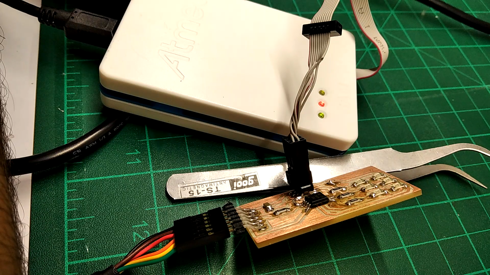
After you finished the fabrication, I bet you that you can't wait to solder it
it's Easy Steps, but be careful because it needs the Patience to make it Work
1. Bring your PCB And Prepare your Tools
2. Put at first some Solder wire on the track before You put the Component, And then put the component on the solder wire and heat it (to place it).
3. put the solder wire and heat it to place the component
4. Repeat the Previous Step again to place The Resistors
5. Repeat the Previous Steps to Place the LEDs
Note
To know the negative side of the LED, you will See Green Thin line in the LED If you looked closer
6. Put the FTDI Headers & ISP Headers To finish your wiring, and Don't forget to put Resistor Leg in the bottom side of the PCB To Connect the Via
7. Connect the ISP To the Programmer & the FTDI cable to the USB of your laptop
Coding
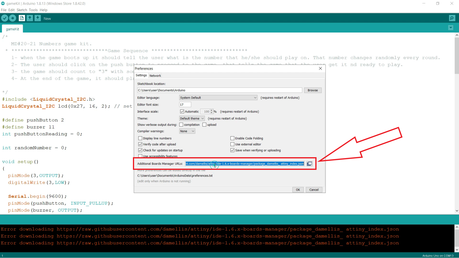
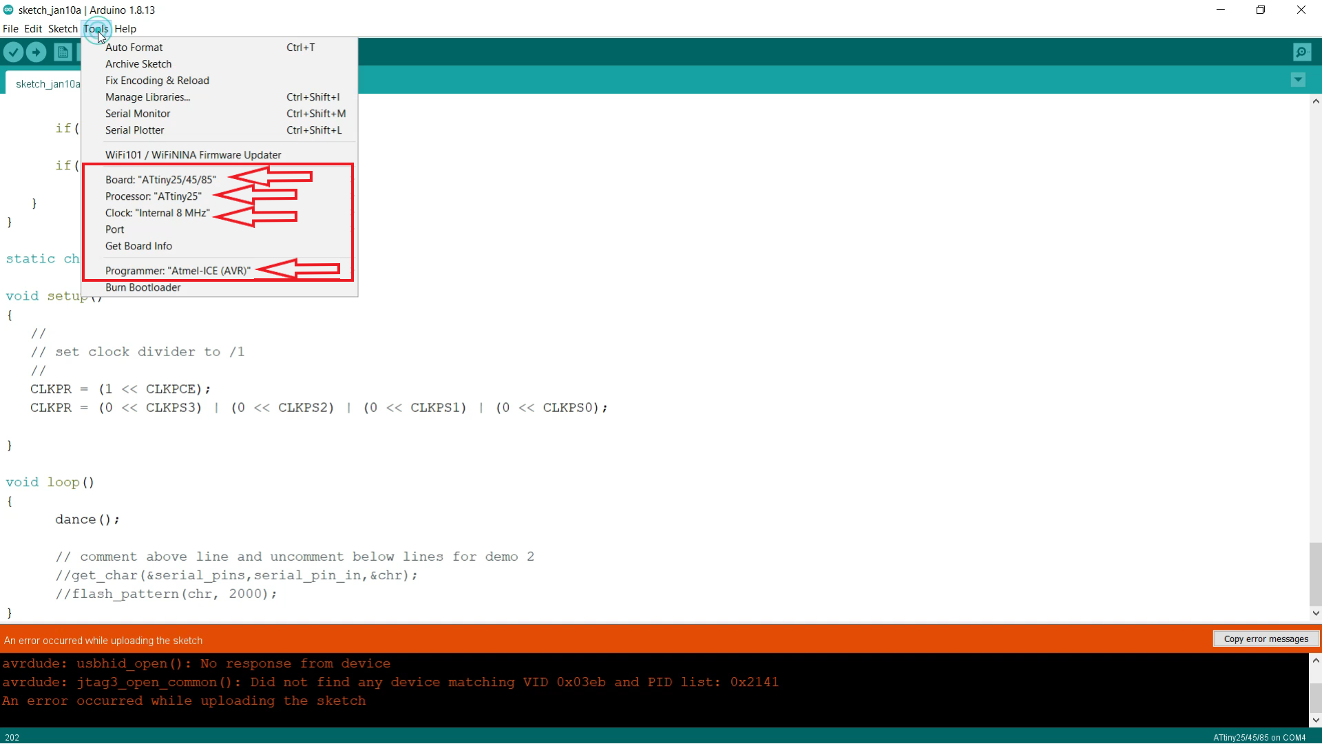
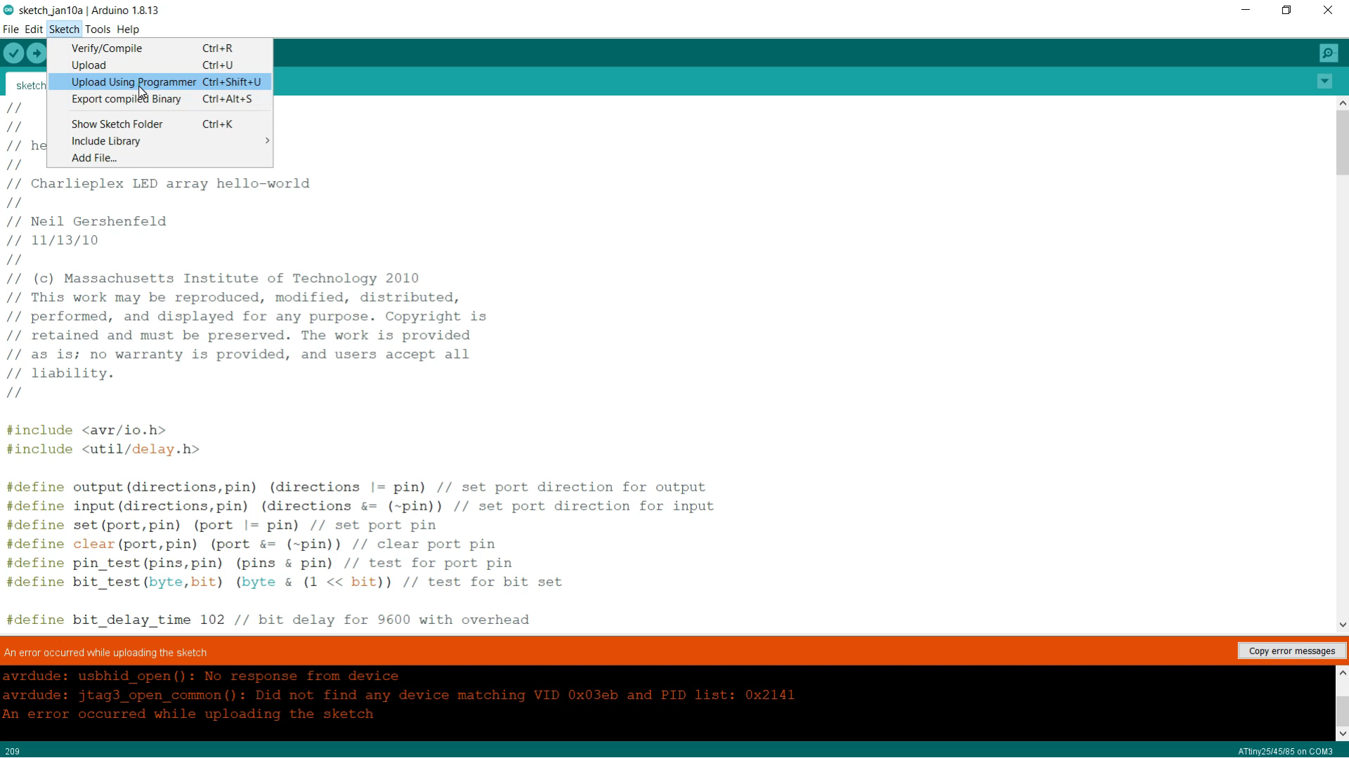
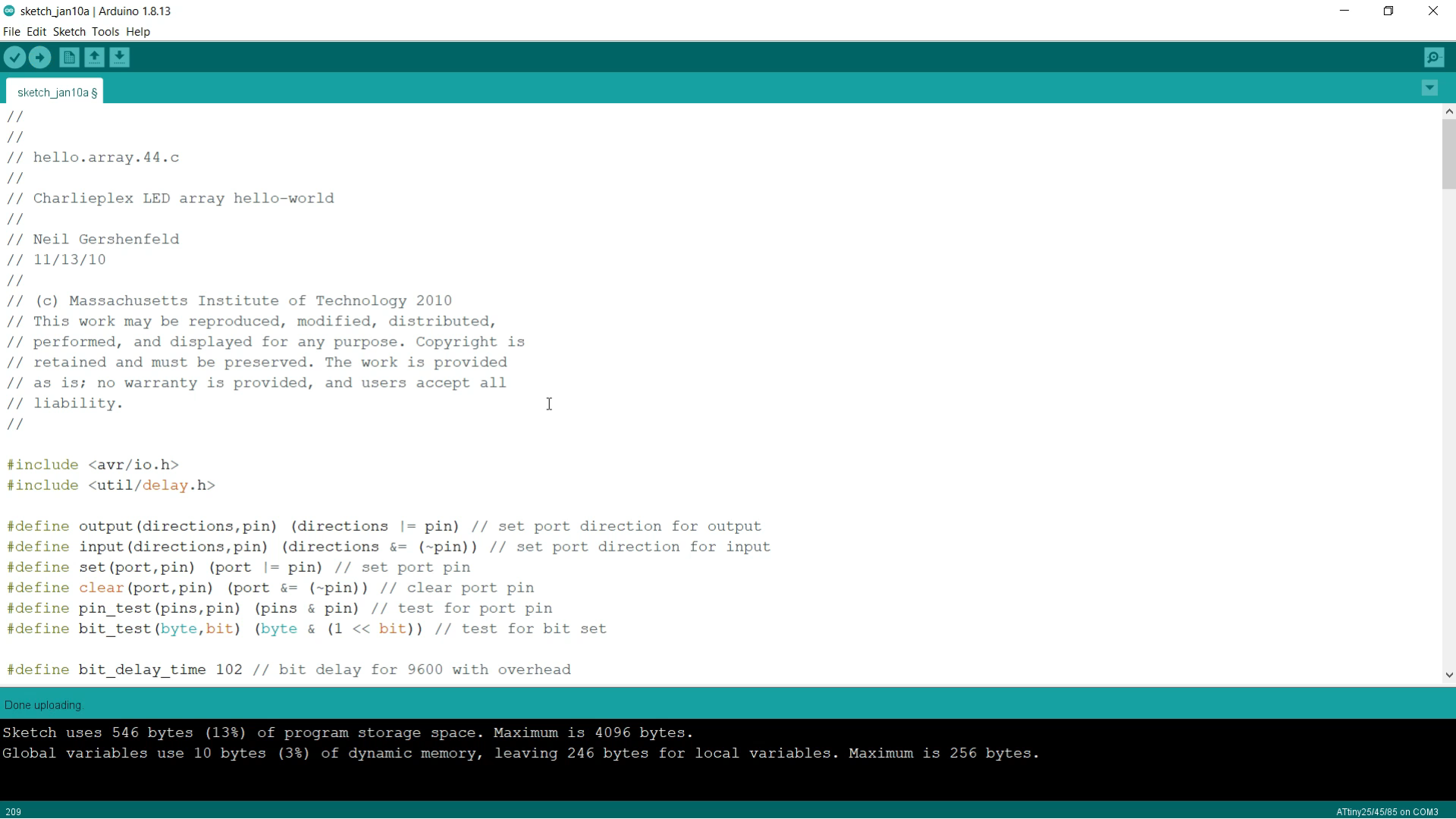
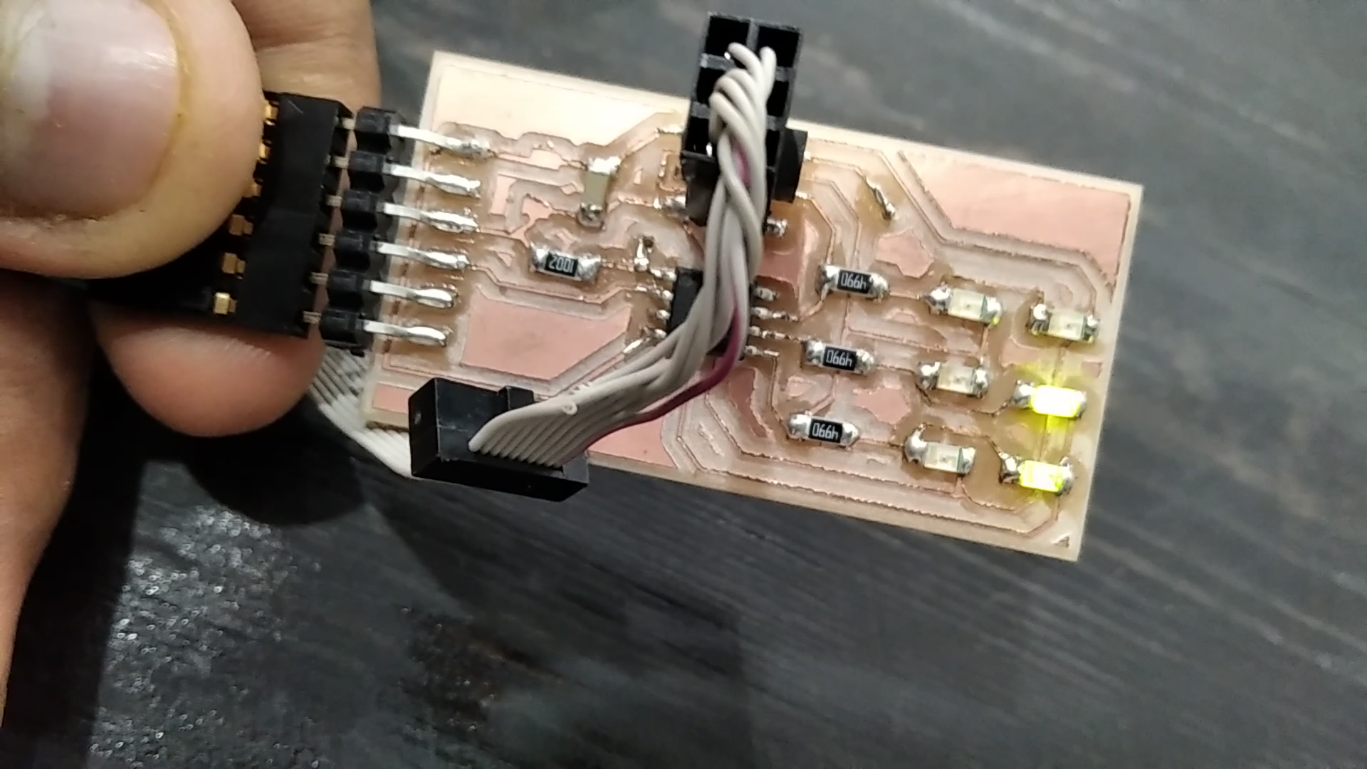
Now that you have a finished board in your hand we are going to upload a code into the embedded microcontroller that will manipulate the LEDs array and display patterns on them.
To complete this task, you will need to download the latest version of Arduino IDE from their website, FTDI cable, your board, and a programmer.
In our case, we will use the ATMEL ICE programmer along with the FTDI to USB converters available in the Lab.
Luckily You wouldn't Write the Code By yourself, I will give you the code
// hello.array.44.c
//
// Charlieplex LED array hello-world
//


#include <avr/io.h>
#include <util/delay.h>


#define output(directions,pin) (directions |= pin) // set port direction for output
#define input(directions,pin) (directions &= (~pin)) // set port direction for input
#define set(port,pin) (port |= pin) // set port pin
#define clear(port,pin) (port &= (~pin)) // clear port pin
#define pin_test(pins,pin) (pins & pin) // test for port pin
#define bit_test(byte,bit) (byte & (1 << bit)) // test for bit set


#define bit_delay_time 102 // bit delay for 9600 with overhead
#define bit_delay() _delay_us(bit_delay_time) // RS232 bit delay
#define half_bit_delay() _delay_us(bit_delay_time/2) // RS232 half bit delay


#define led_delay() _delay_ms(1) // LED delay


#define flash_delay 1


#define led_port PORTB
#define led_direction DDRB


#define C (1 << PB0) // row 1
#define B (1 << PB1) // row 2
#define A (1 << PB2) // row 3


#define serial_port PORTB
#define serial_direction DDRB
#define serial_pins PINB
#define serial_pin_in (1 << PB3)


void get_char(volatile unsigned char *pins, unsigned char pin, char *rxbyte) {
   //
   // read character into rxbyte on pins pin
   //    assumes line driver (inverts bits)
   //
   *rxbyte = 0;
   while (pin_test(*pins,pin))
      //
      // wait for start bit
      //
      ;
   //
   // delay to middle of first data bit
   //
   half_bit_delay();
   bit_delay();
   //
   // unrolled loop to read data bits
   //
   if pin_test(*pins,pin)
      *rxbyte |= (1 << 0);
   else
      *rxbyte |= (0 << 0);
   bit_delay();
   if pin_test(*pins,pin)
      *rxbyte |= (1 << 1);
   else
      *rxbyte |= (0 << 1);
   bit_delay();
   if pin_test(*pins,pin)
      *rxbyte |= (1 << 2);
   else
      *rxbyte |= (0 << 2);
   bit_delay();
   if pin_test(*pins,pin)
      *rxbyte |= (1 << 3);
   else
      *rxbyte |= (0 << 3);
   bit_delay();
   if pin_test(*pins,pin)
      *rxbyte |= (1 << 4);
   else
      *rxbyte |= (0 << 4);
   bit_delay();
   if pin_test(*pins,pin)
      *rxbyte |= (1 << 5);
   else
      *rxbyte |= (0 << 5);
   bit_delay();
   if pin_test(*pins,pin)
      *rxbyte |= (1 << 6);
   else
      *rxbyte |= (0 << 6);
   bit_delay();
   if pin_test(*pins,pin)
      *rxbyte |= (1 << 7);
   else
      *rxbyte |= (0 << 7);
   //
   // wait for stop bit
   //
   bit_delay();
   half_bit_delay();
   }


void flash(uint8_t from, uint8_t to, uint8_t delay) {
   //
   // source from, sink to, flash
   //
   static uint8_t i;
   set(led_port,from);
   clear(led_port,to);
   output(led_direction,from);
   output(led_direction,to);
   for (i = 0; i < delay; ++i)
       led_delay();
   input(led_direction,from);
   input(led_direction,to);
   }


void led_cycle_CCW(uint8_t number, uint8_t delay) {
   //
   // cycle through LEDs
   //
   uint8_t i;
   for (i = 0; i < number; ++i) {
      flash(A,B,delay);
      flash(A,C,delay);
      flash(B,A,delay);
      flash(B,C,delay);
      flash(C,A,delay);
      flash(C,B,delay);
      }
   }
void led_cycle_CW(uint8_t number, uint8_t delay) {
   //
   // cycle through LEDs
   //
   uint8_t i;
   for (i = 0; i < number; ++i) {
      flash(C,B,delay);
      flash(B,C,delay);
      flash(B,A,delay);
      flash(C,A,delay);
      flash(A,C,delay);
      flash(A,B,delay);
      }
   }


void flash_all(uint8_t number)
{
   for (int i = 0; i < number; ++i)
   {
      flash(A, B, flash_delay);
      flash(A, C, flash_delay);
      flash(B, A, flash_delay);
      flash(B, C, flash_delay);
      flash(C, A, flash_delay);
      flash(C, B, flash_delay);
   }
}
void dance(void)
{
   led_cycle_CCW(10, 50);
   flash_all(100);
   led_cycle_CW(10, 50);
   flash_all(100);
}


void flash_pattern(uint8_t pattern, uint8_t number)
{
   for (int i = 0; i < number; ++i)
   {
      if((pattern >> 1) & (1))
         flash(A, B, flash_delay);
      if((pattern >> 2) & (1))
         flash(A, C, flash_delay);


      if((pattern >> 3) & (1))
         flash(B, A, flash_delay);
      if((pattern >> 4) & (1))
         flash(B, C, flash_delay);


      if((pattern >> 5) & (1))
         flash(C, A, flash_delay);
      if((pattern >> 6) & (1))
         flash(C, B, flash_delay);
   }
}


static char chr;


void setup()
{
   //
   // set clock divider to /1
   //
   CLKPR = (1 << CLKPCE);
   CLKPR = (0 << CLKPS3) | (0 << CLKPS2) | (0 << CLKPS1) | (0 << CLKPS0);

}


void loop()
{
      dance();


      // comment above line and uncomment below lines for demo 2
      //get_char(&serial_pins,serial_pin_in,&chr);
      //flash_pattern(chr, 2000);
}
____________________________________
Download the latest Arduino IDE from their website
Arduino Download
Arduino IDE naturally doesn’t support the microcontroller we are using in the board, so you
should add support for our microcontroller ATtiny45. The first step is to add a link to the support package by going to file->preferences->Additional Boards Manager URLs then paste the
following link :
https://raw.githubusercontent.com/damellis/attiny/ide-1.6.x-boards-manager/package_damellis_attiny_index.json
The next step is installing the support package by going to tools->Boards->Boards Manager
then search for Attiny and click install.
Now we have the Arduino IDE that supports the microcontroller we are using.
The next step would be setting up the controller and the programmer settings.
Go to tools->Boards->ATtinymicrocontrollers->then select Attiny25/45/85.
For the next step go to tools->processor-> then select ATtiny45.
Then go to tools->clock-> then select internal 8 MHz.
The final step is configuring the programmer by going to Tools ->Programmers and then selecting Atmel ICE (AVR).
Now the Arduino IDE is fully configured and we are ready
And Now click on Sketch and then click on Upload Using Programmer
And here is our PCB Yeah
Downloads
Video
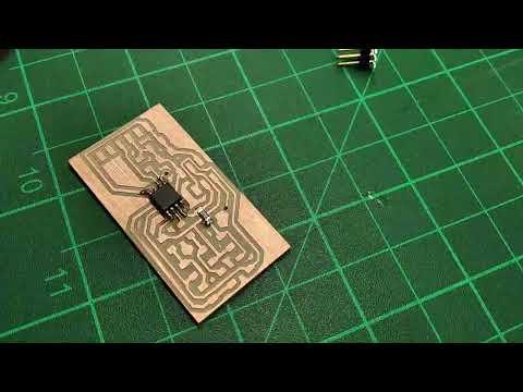
Here is a speedup video for all the journey
Issue & Solution
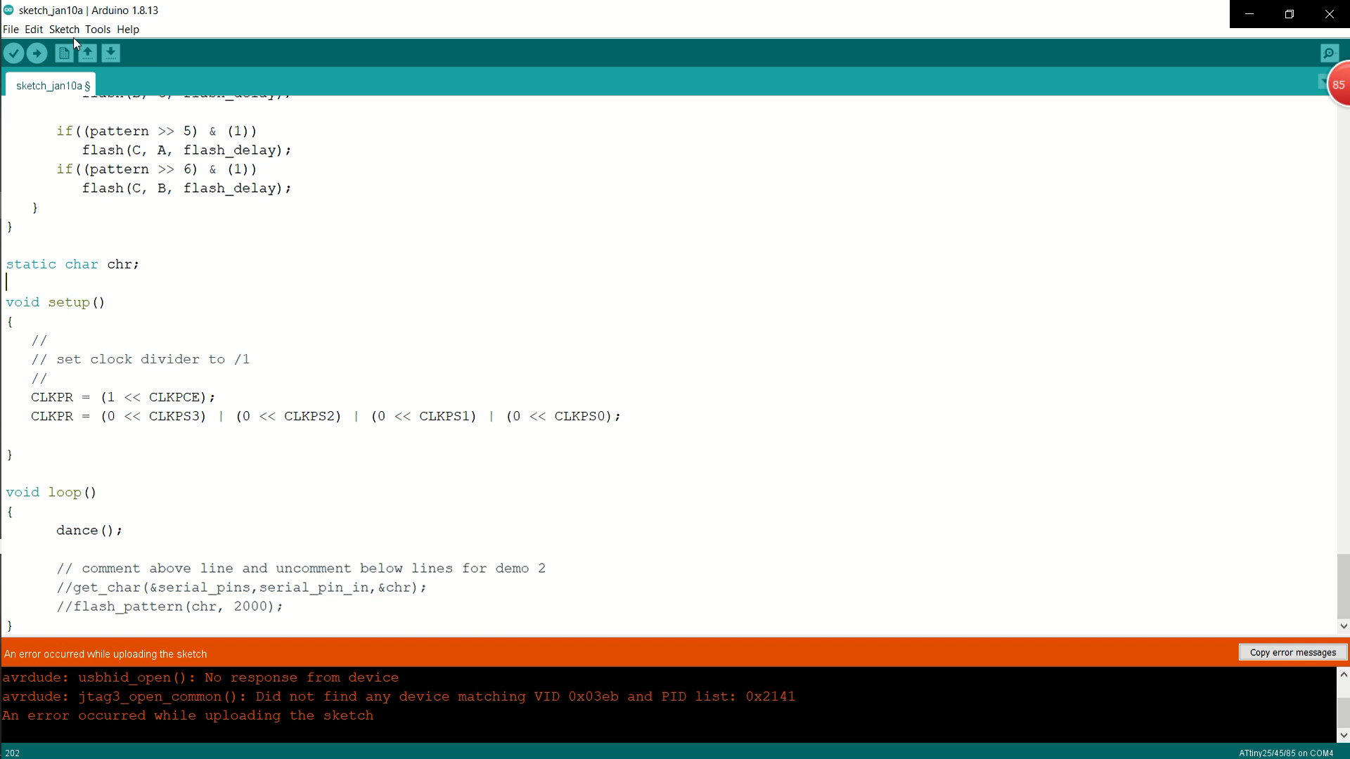
Here I will give you the Problems I faced and the Solution to It
Issue1:
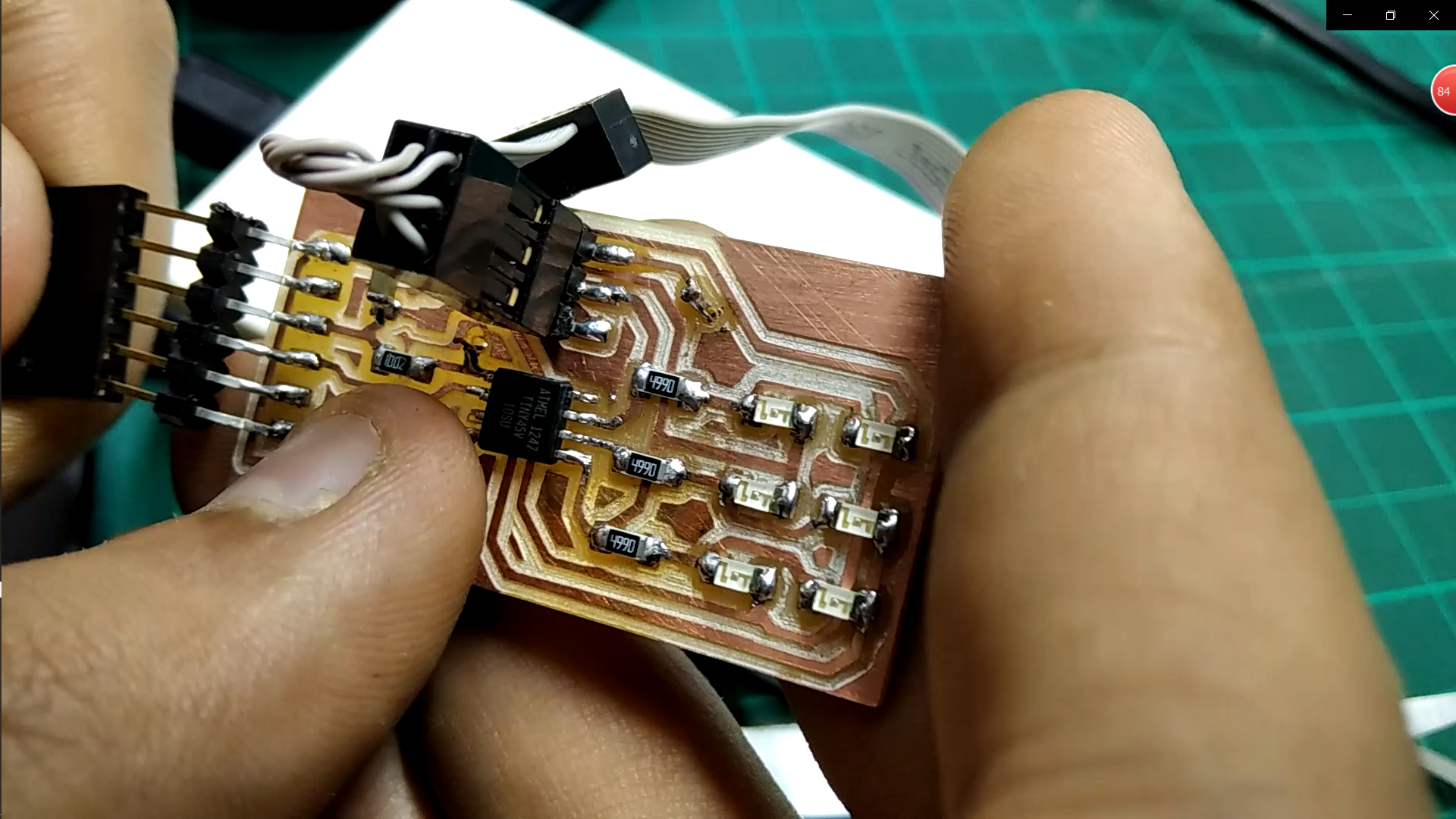
The Code does not upload
Solution: Make sure that you are put the ISP cable in the Correct direction
________________________________________________________
Issue2:
The Machine didn't Cut the Holes
Solution: You probably made something wrong on gimp, make sure that the Holes and the outer frame are shaded with black not white
_____________________________________________________
Issue3:
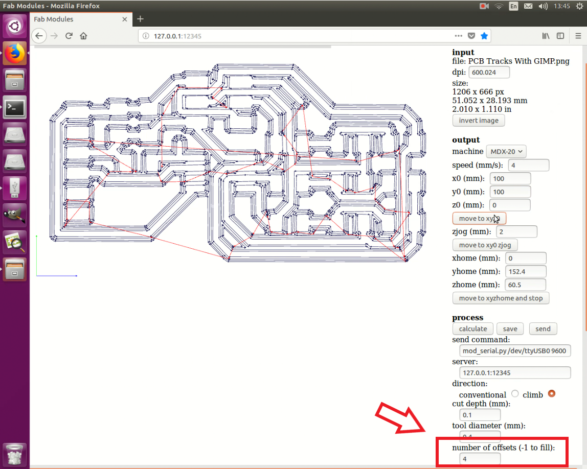
Tracks width is thin
Solution: then you can adjust the offset by 2 not 4
Interfacing
Here is another tutorial for interfacing the LED Matrix with computer software made by Processing