LED Light Module for Your PC
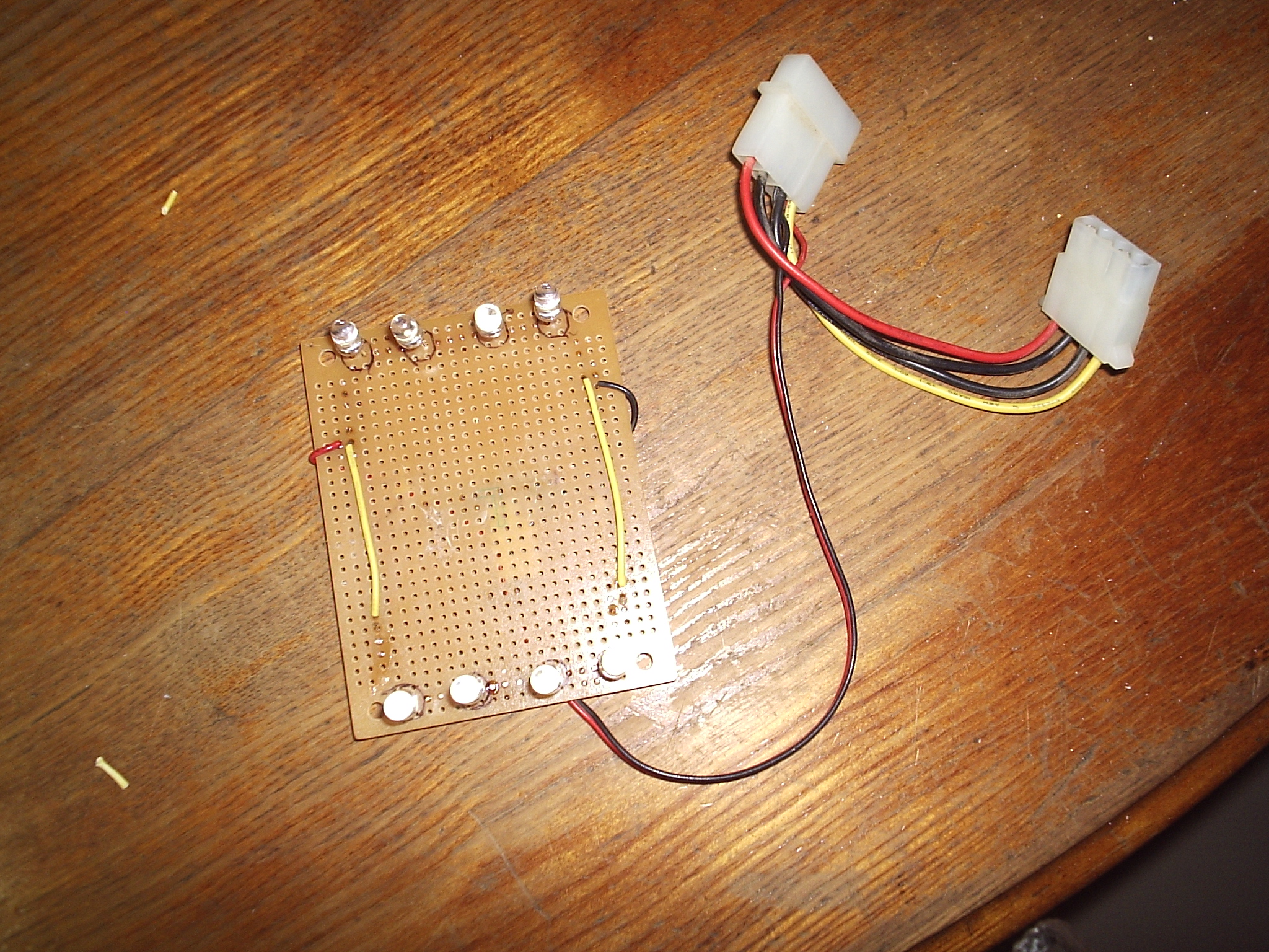
In this instructable I am going to show you how to build a LED lighting module for the inside of your computer. This module uses eight LEDs in a series-parallel circuit. You can use any number of LEDs that is a multiple of four.
If you are interested in one of these I can custom build one for you for ten dollars. Check out this link:
https://www.instructables.com/community/Custom-Built-LED-Module-for-Your-PC/
Materials and Tools
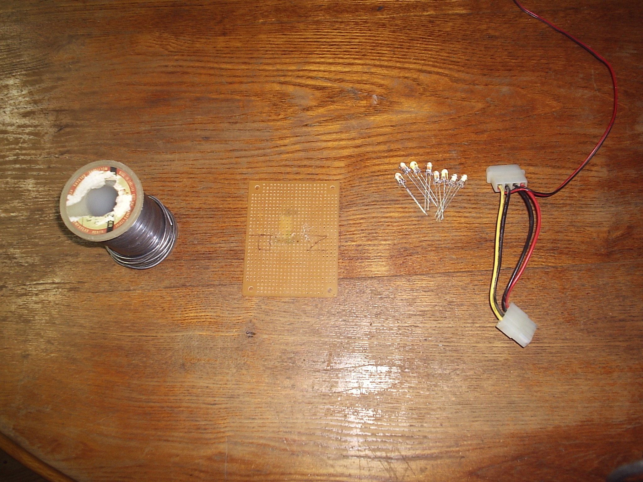
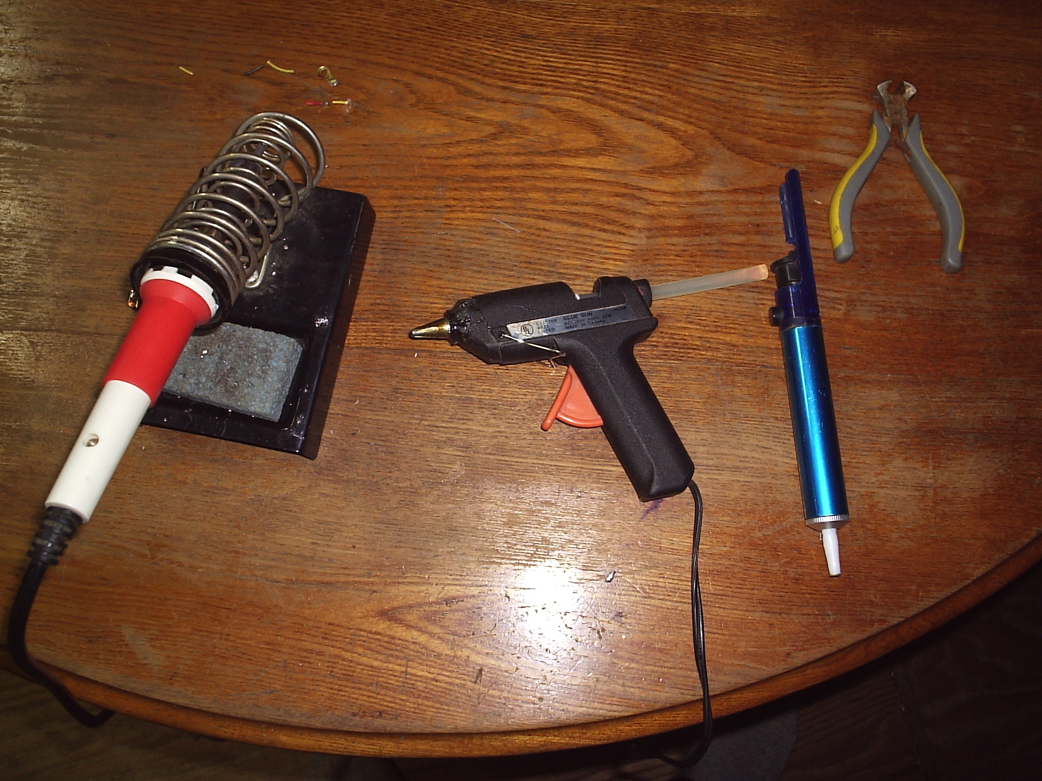
Here are the materials you will need:
- LEDs. I used 5mm white, high intensity, water clear LEDs. I got 100 hundred of them for six dollars off of EBAY.
- A Breadboard. You can use any size breadboard you want. I got mine online but you can also get them at Radio Shack for a price.
- Wire. You need a couple of two to three inch pieces of small gauge wire.
- Molex power connector. This plugs into the molex power connector in your computer and provides power to your LED board. You can probably strip one of these from an old computer fan.
- Soldering Iron. I bet you can guess what we are going to use this for.
- Hot Glue Gun. This is for gluing down any loose wires.
- Solder Sucker. This may come in handy if you mess up and need to remove a LED.
- Craft Foam. This is optional, I like to use it for insulating the back of the circuit board.
The Circuit
.JPG)
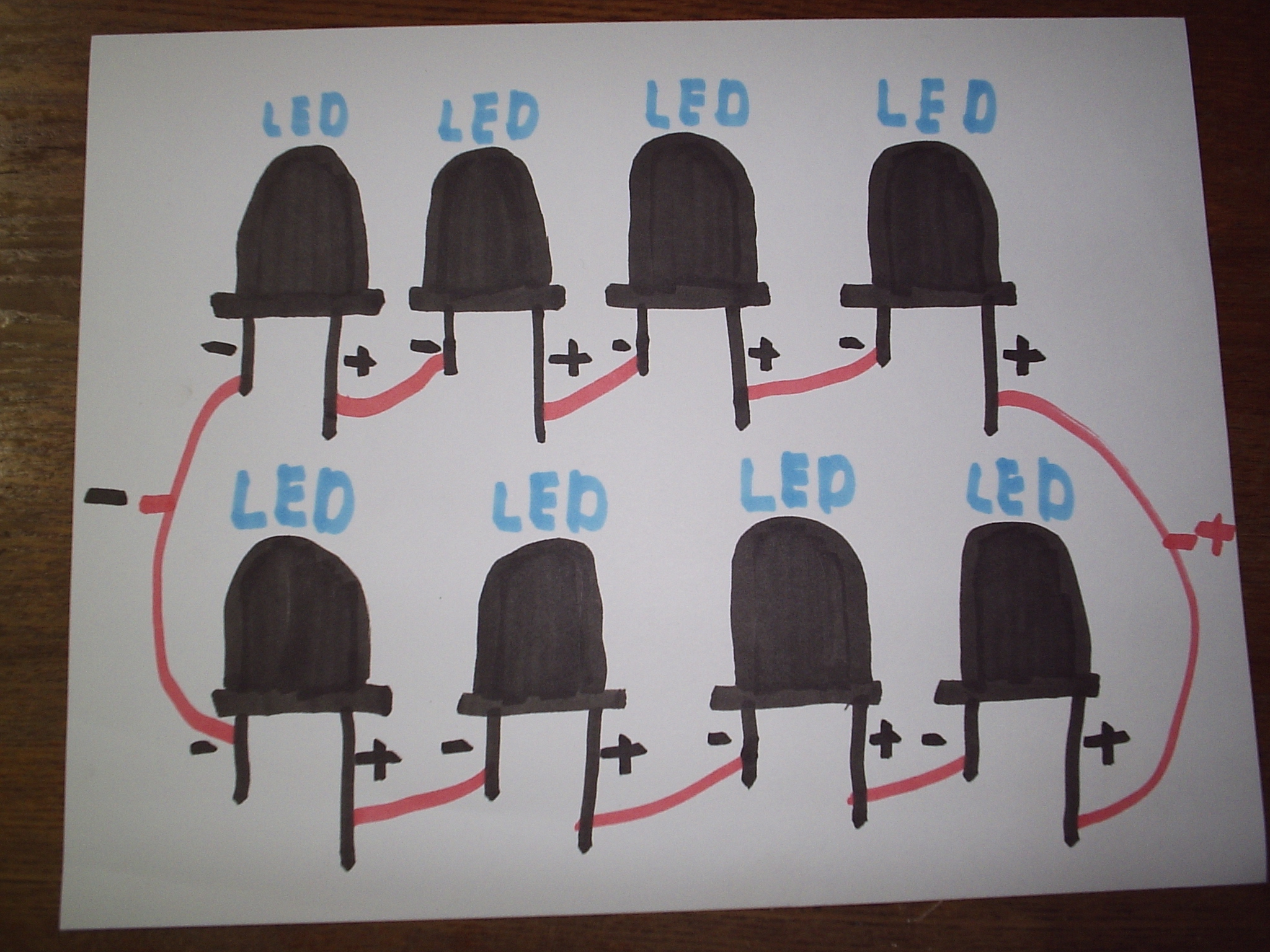
The LEDs are arranged in what is called a series-parallel circuit. First we make two strings of four LEDs these are hooked together in series. Then we hook the two four LED strings together in parallel.
The reason that the first strings are hooked in parralel is this. Each LED runs on three volts, so since we are using a twelve volt power source we need to put four LEDs in series. This way each LED is running at three volts. If we ran the LEDs in parallel then each one would be running at twelve volts and would burn out because of to much voltage. Now we could just use four LEDs, but four LEDs don't provide much light so what I did was run another string of four LEDs in parallel with the first string. If I ran the second string in series with the first then all of the LEDs would be running at 1.5 volts and would be to dim to be of much use. You can look at the pictures if you need more clarification.
The reason that the first strings are hooked in parralel is this. Each LED runs on three volts, so since we are using a twelve volt power source we need to put four LEDs in series. This way each LED is running at three volts. If we ran the LEDs in parallel then each one would be running at twelve volts and would burn out because of to much voltage. Now we could just use four LEDs, but four LEDs don't provide much light so what I did was run another string of four LEDs in parallel with the first string. If I ran the second string in series with the first then all of the LEDs would be running at 1.5 volts and would be to dim to be of much use. You can look at the pictures if you need more clarification.
Marking LED Positions
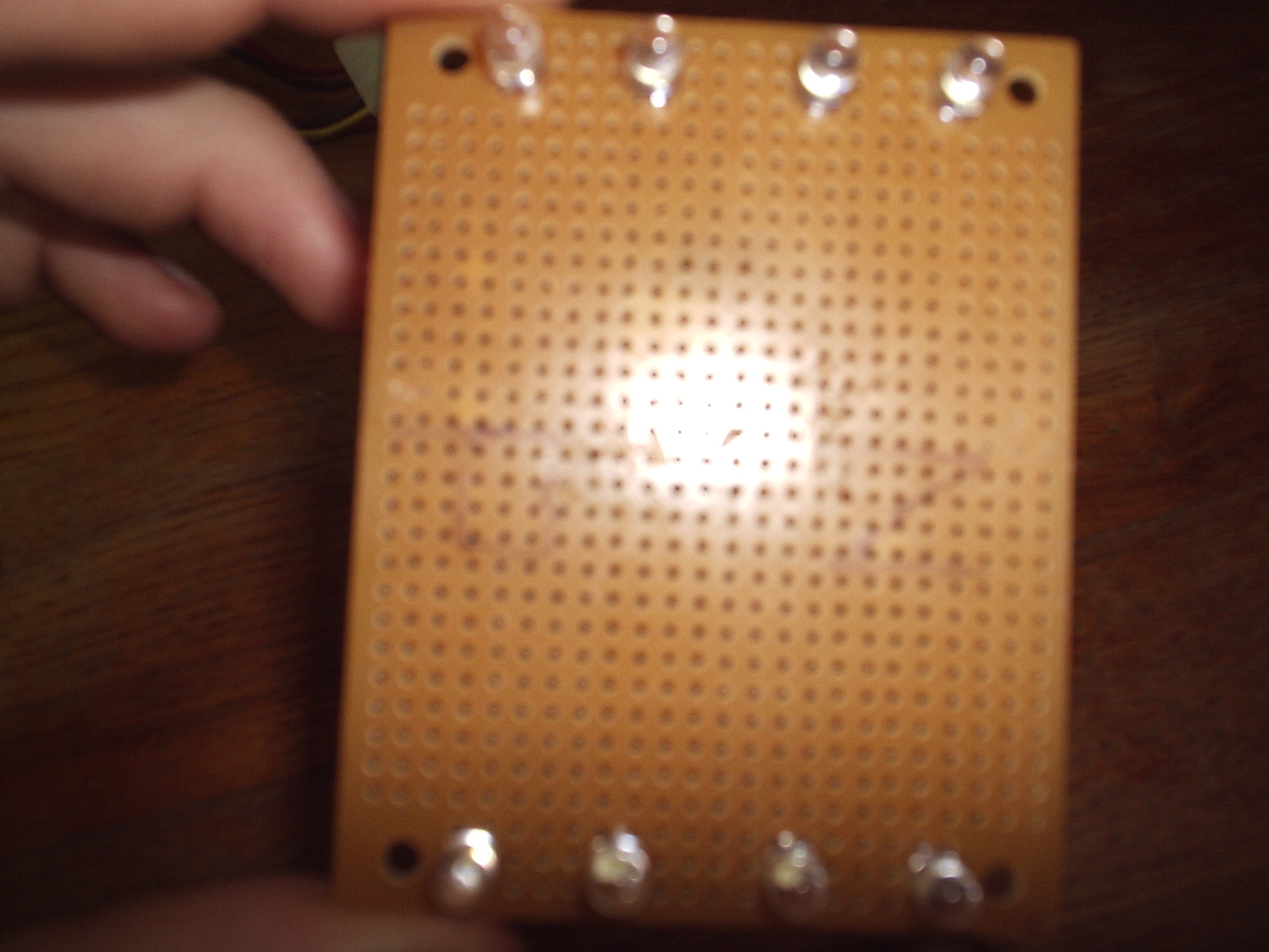
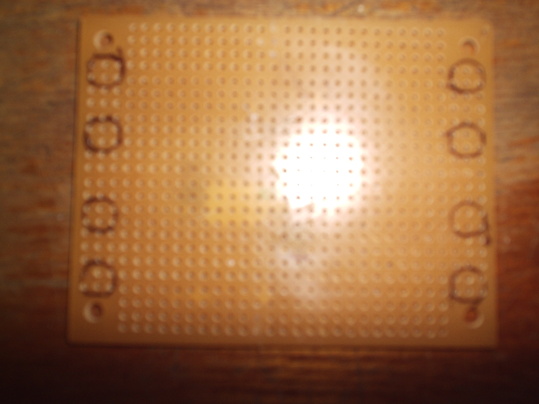
Now we need to figure out where you are going to solder your LEDs. I positioned one string of four LEDs at each end of the breadboard. I would recomend putting them a couple of holes in so that the LEDs don't overhang the edge. Now you can solder on your LEDS so that they are flat against the board, but I would recommend that you leave the LEDs about a half inch above the board. By doing this you make it so that you can move each LED a little bit if you need to. Once you have figured out the spacing of each LED draw a circle around it so that when you are soldering you know where each LED goes. Once you have all of the LED positions marked you are ready to move to the next step and start soldering.
Soldering
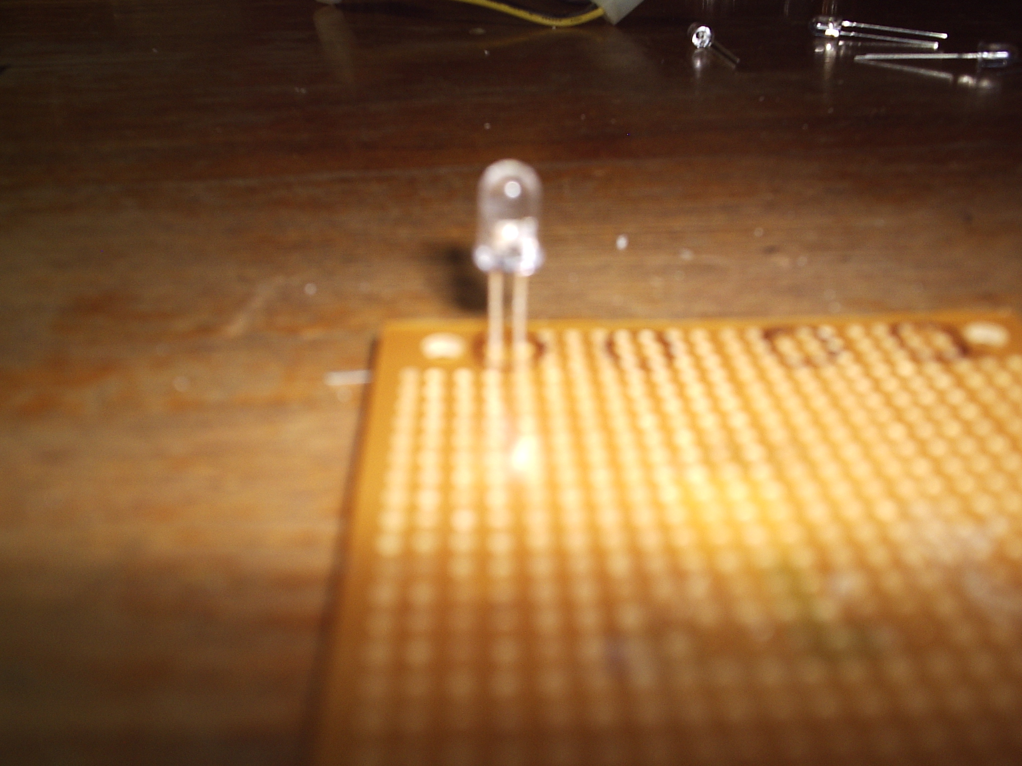
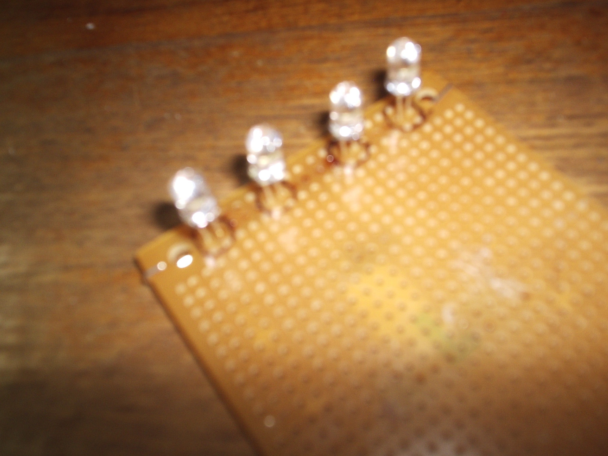
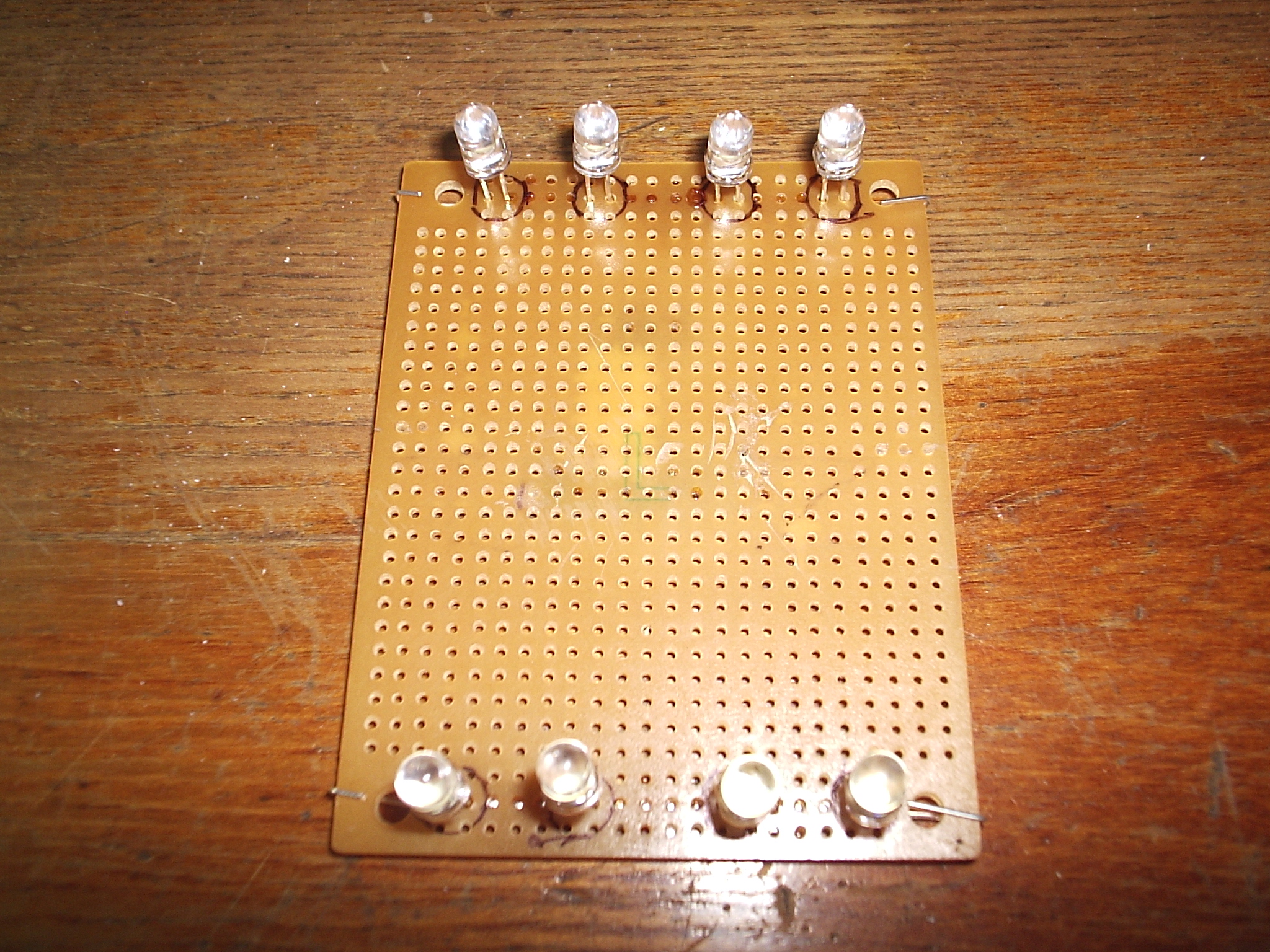
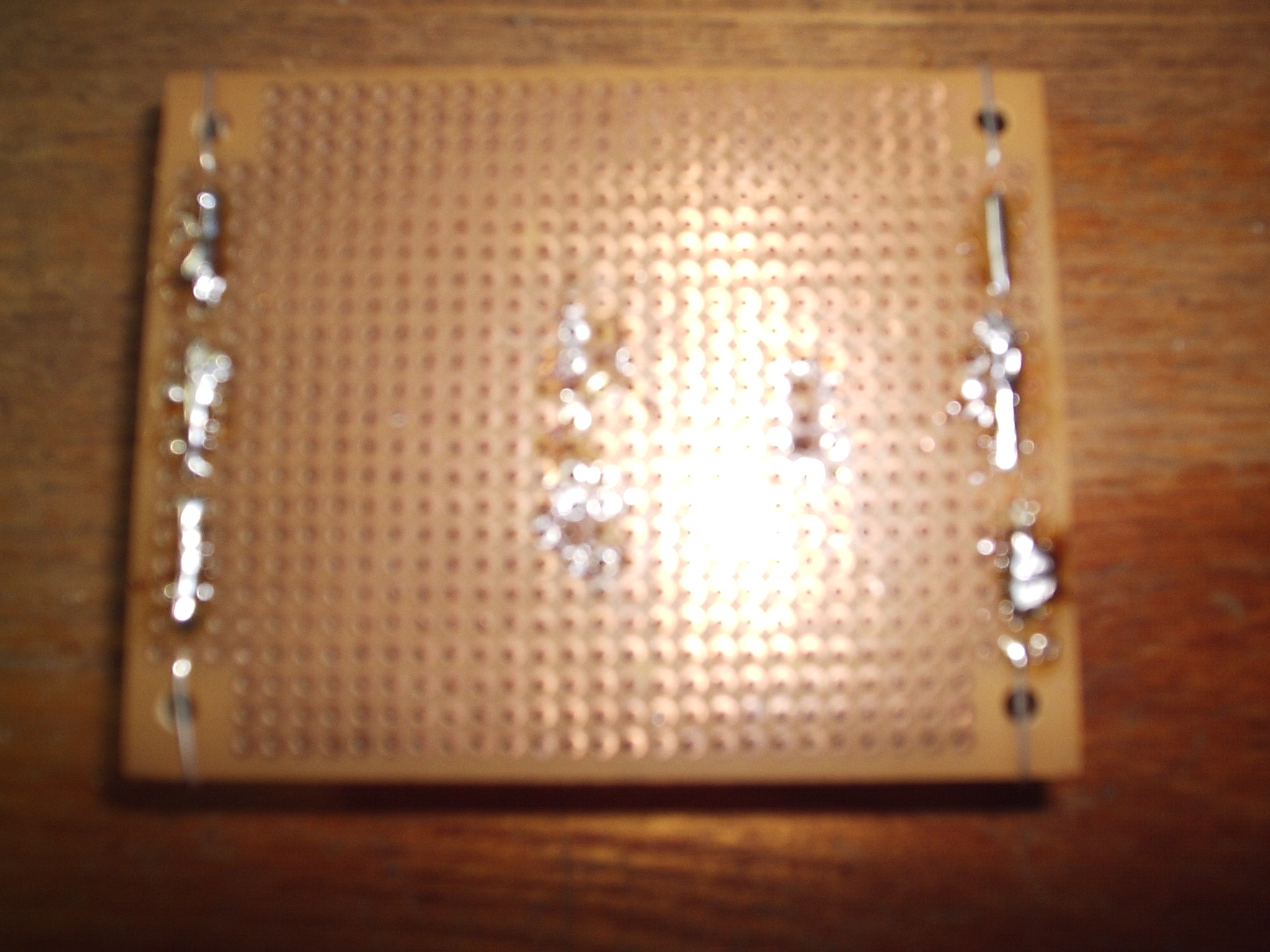
Now you are ready to solder on your LEDs. Remember to leave a half inch of space between the LED body and the circuit board. Solder on the string of LEDs at each end first, we'll worry about connecting the two strings later. Look at the pictures to see how I soldered on the LEDs in general follow these steps:
- Push the LED leads through the breadboard holes. Make sure to leave a half inch between the LED body and the circuit board.
- Once you have the LED correctly positioned bend over the leads to hold it in place until you are ready to solder it on.
- Carefully solder on the LEDs. Use the leads to connect them together. You must remember to solder quickly so that you don't damage the LED with excessive heat.
Hooking the Strings Together
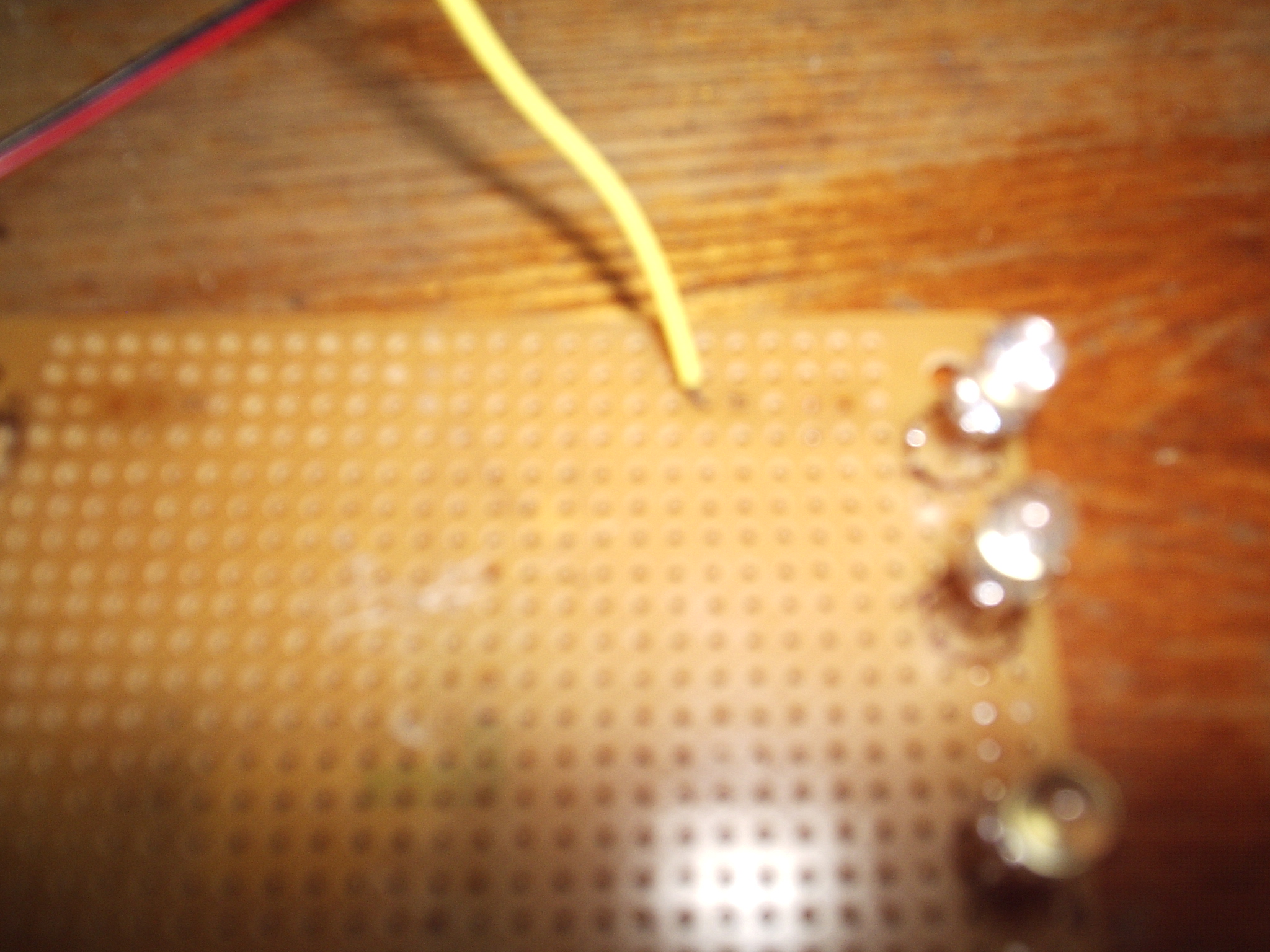
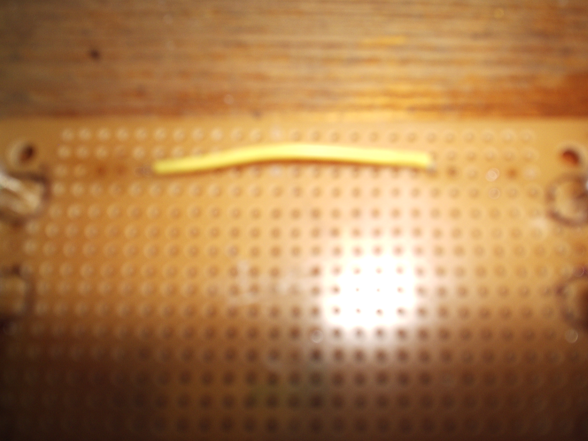
Now we are going to add the parallel part to our series-parallel circuit. We are going to do this by hooking the two series strings together in parallel. That means we are going to hook the positive end of both strings together. We will also hook both negative ends together. To do this we will use two short pieces of small gauge wire. Follow these steps:
- Cut two two to three inch pieces of wire.
- Strip both end about 3/8 of an inch.
- Position the wires on top of the circuit board.
- Push the stripped ends through the breadboard so they make contact with the end of the LED string.
- Solder the wires on.
Connecting the Power Adapter
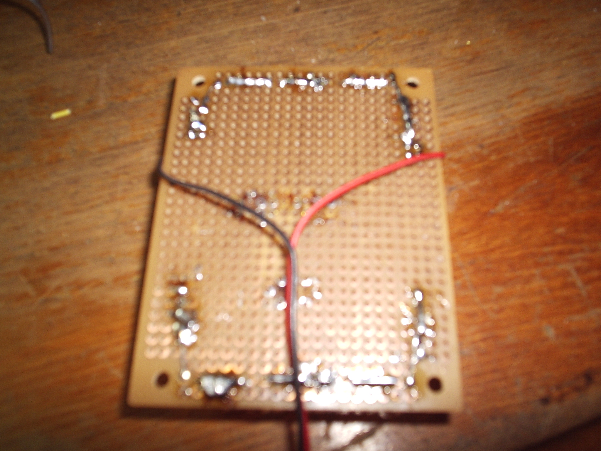
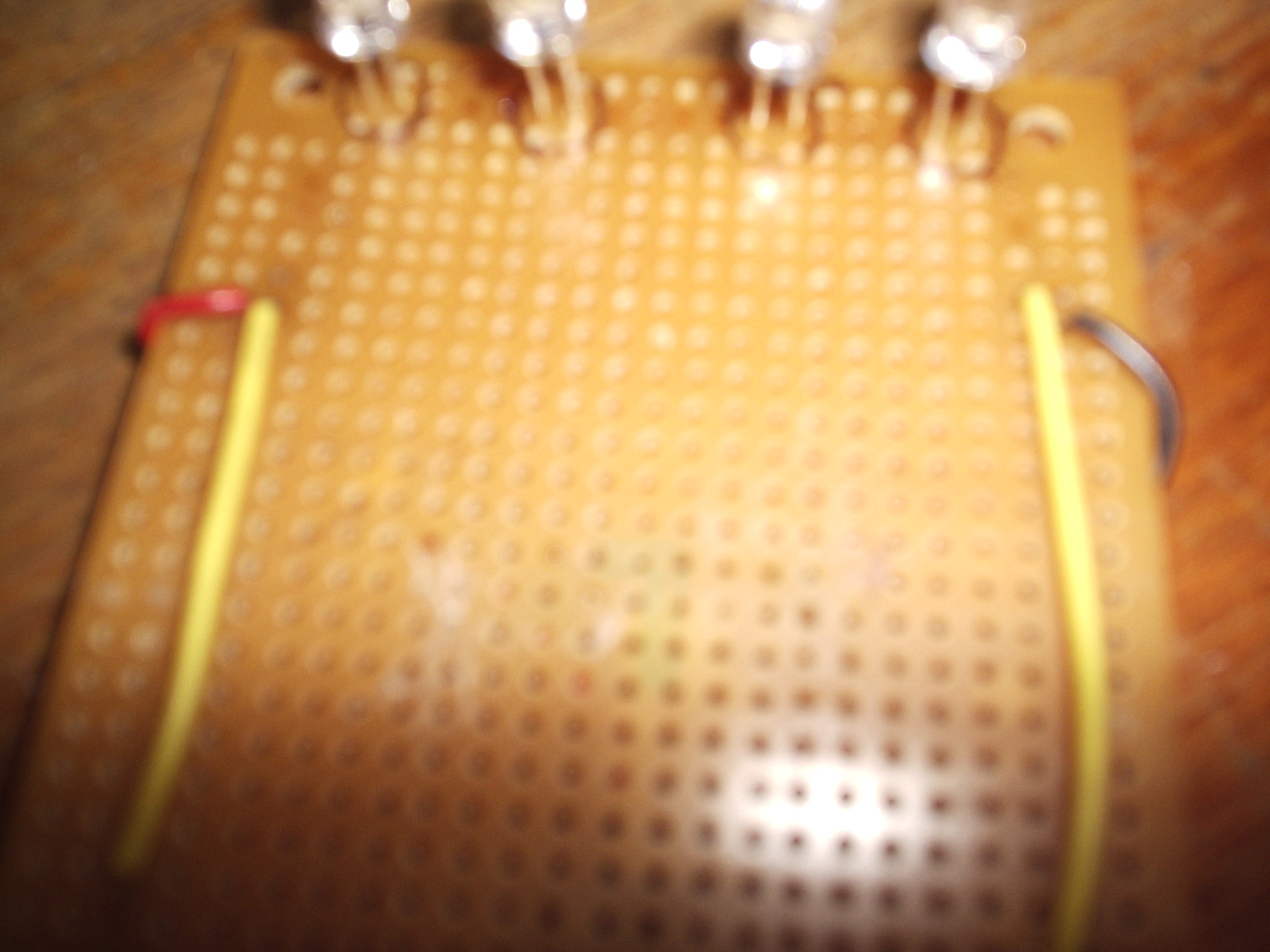
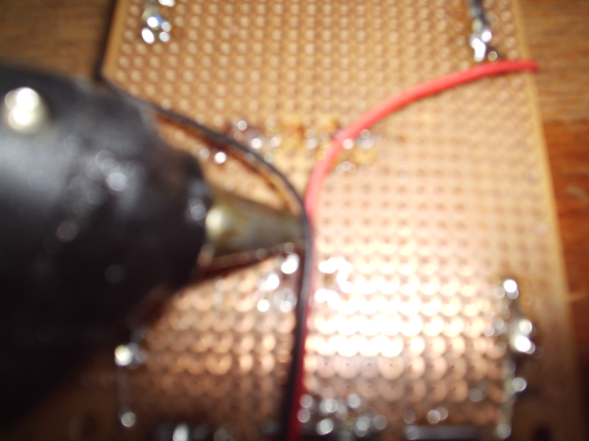
Now we are going to connect the power adapter that will give our lighting module power. Your power connector should have two molex connectors (one male and one female) it should also have two other wires. There should be one red wire and one black wire the red is positive and the black is negative. Solder these to the corresponding positive and negative on your LED board.
Adding Insulating Foam
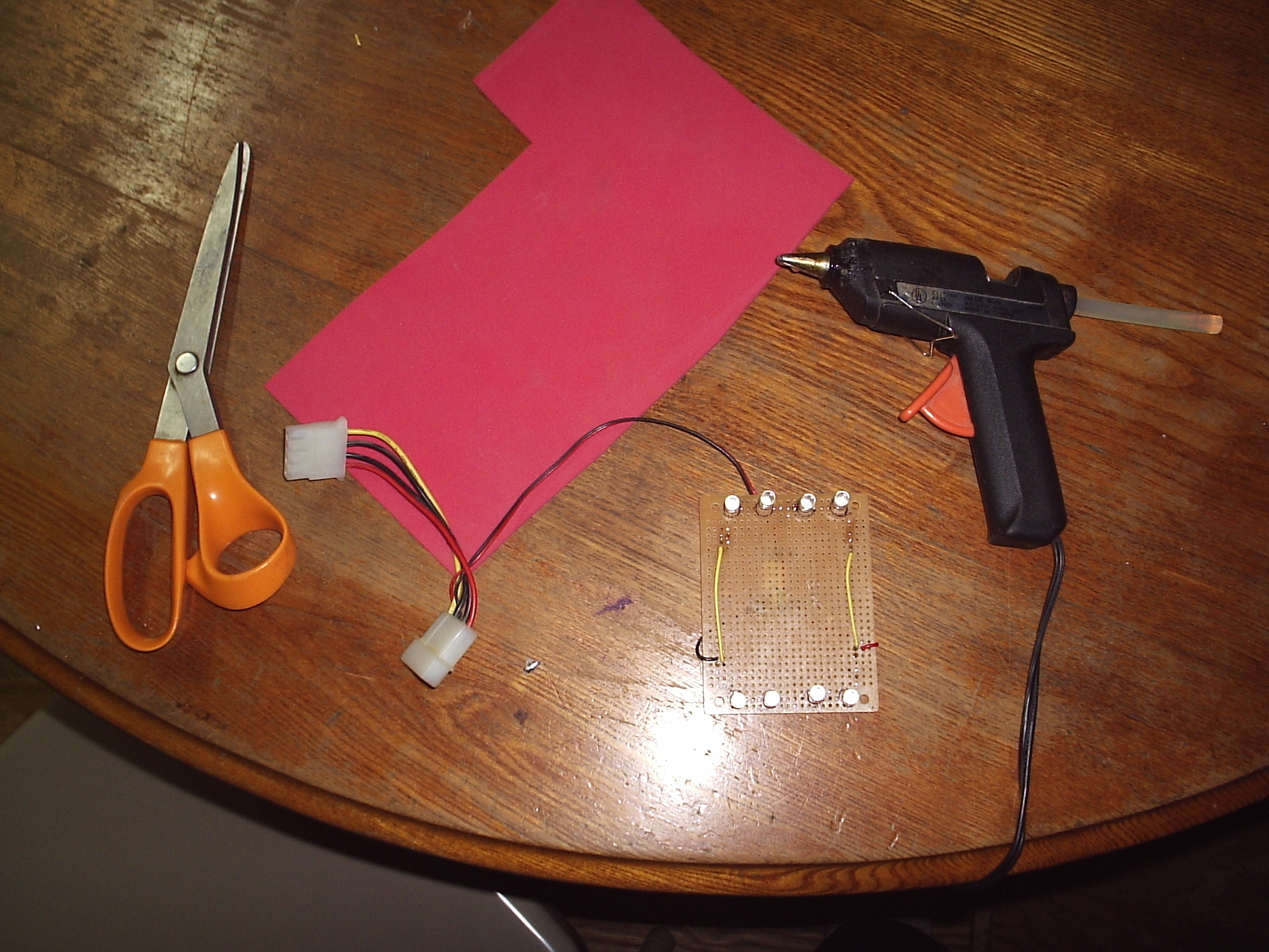
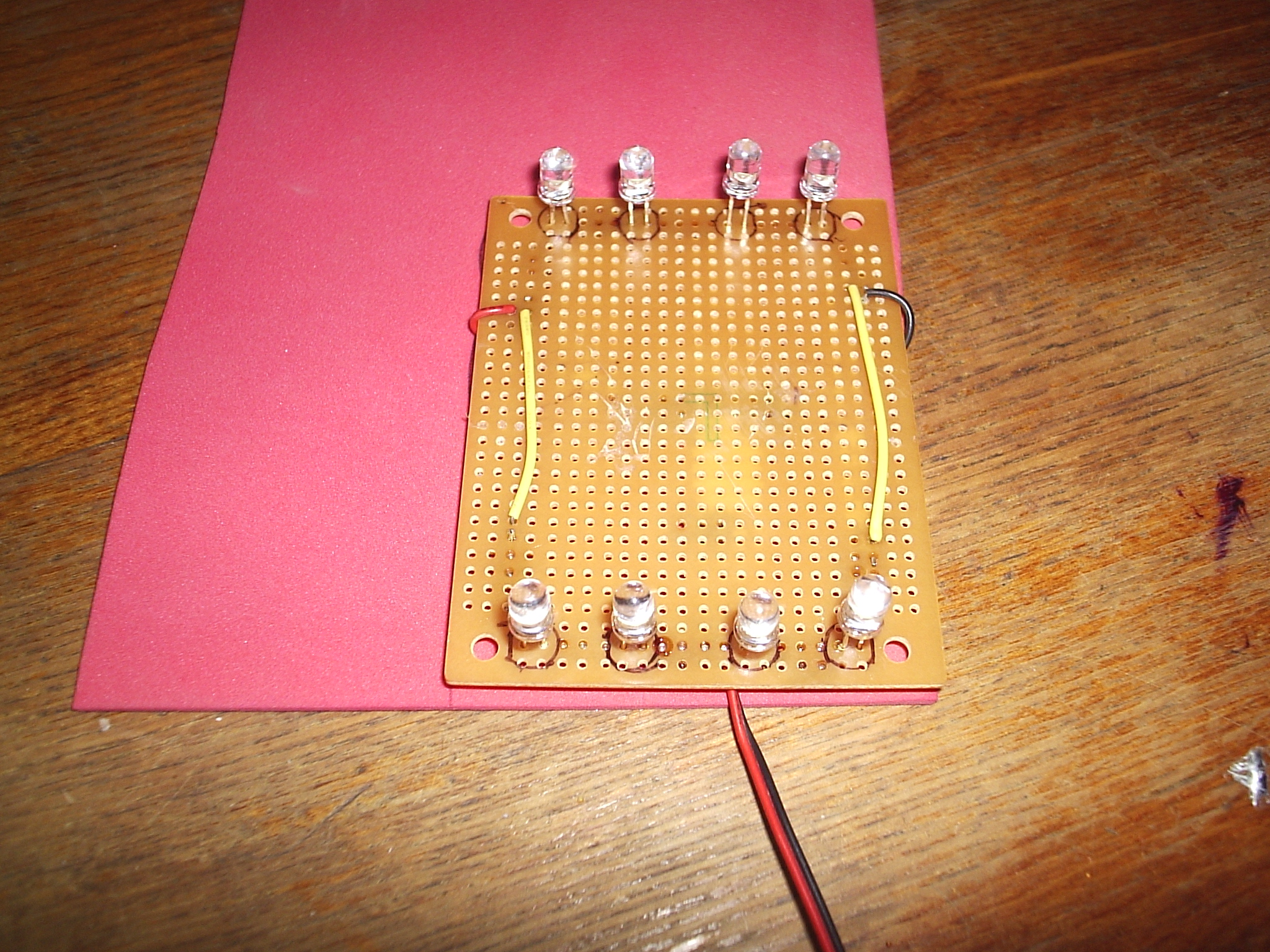
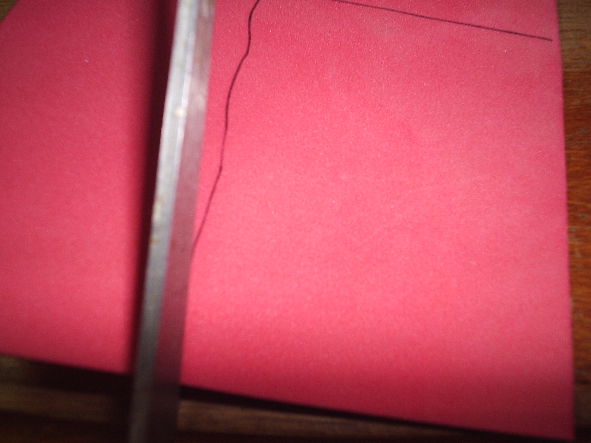
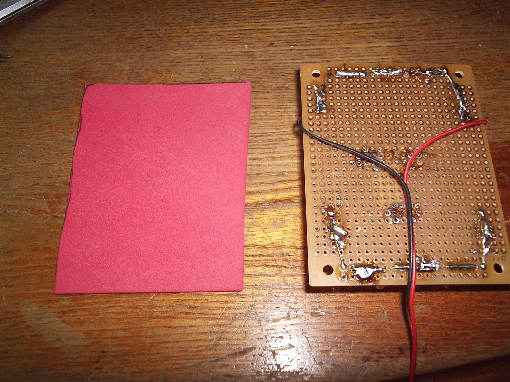
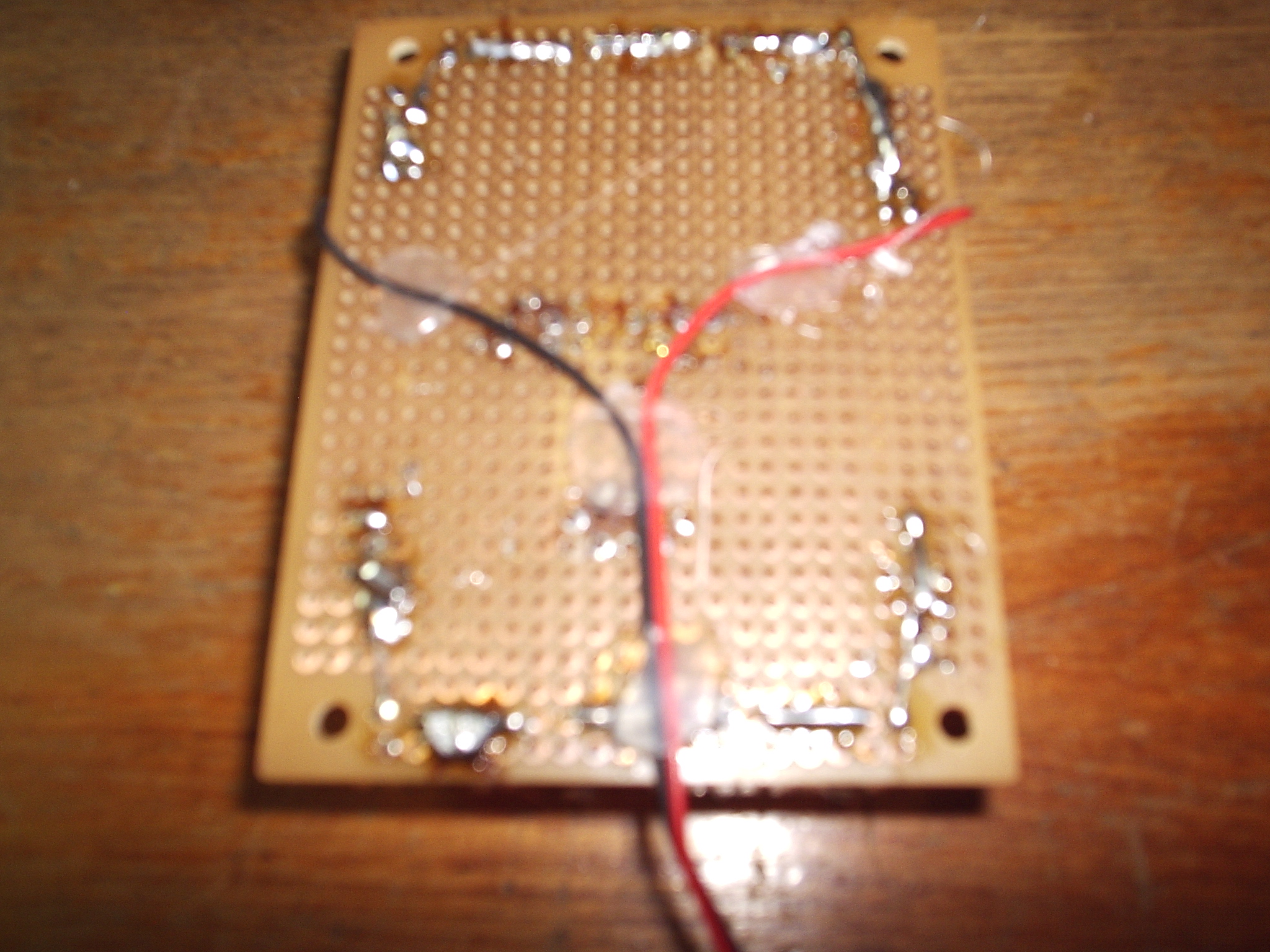
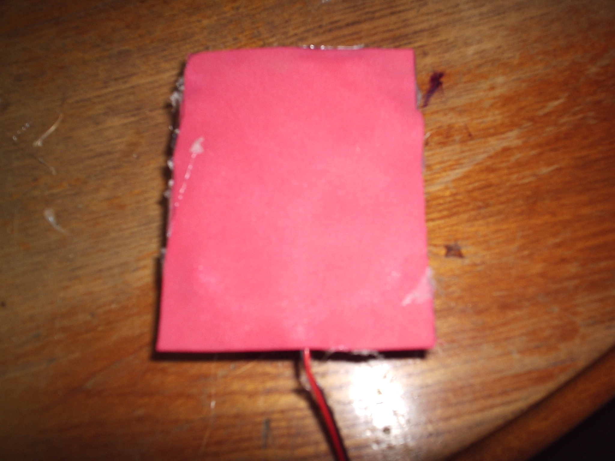
This step is actually optional but I would recommend you do it because it will insulate your electrical connections and make everything much safer. Follow these steps:
- Using hot glue, glue your power adapter wire to the circuit board.
- Find some craft foam and cut out a piece the same size as your circuit board. If you can't find any craft foam you can use cardboard.
- Using lots and lots of hot glue fasten the foam to the circuit board. I glued in the middle, pushed on the foam, and then squirted glue into the edges.
Pictures and Final Thoughts
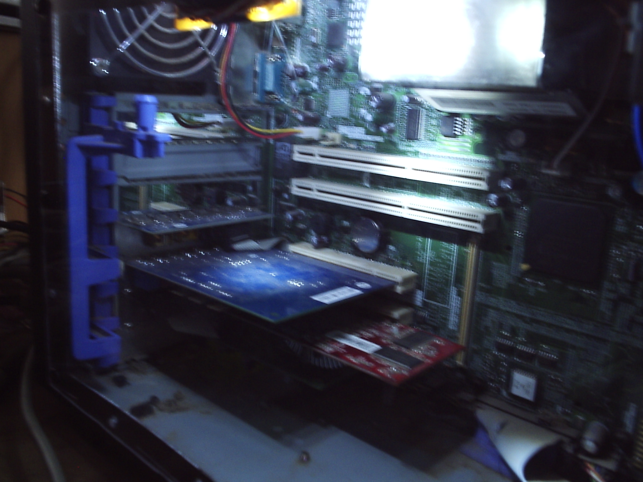
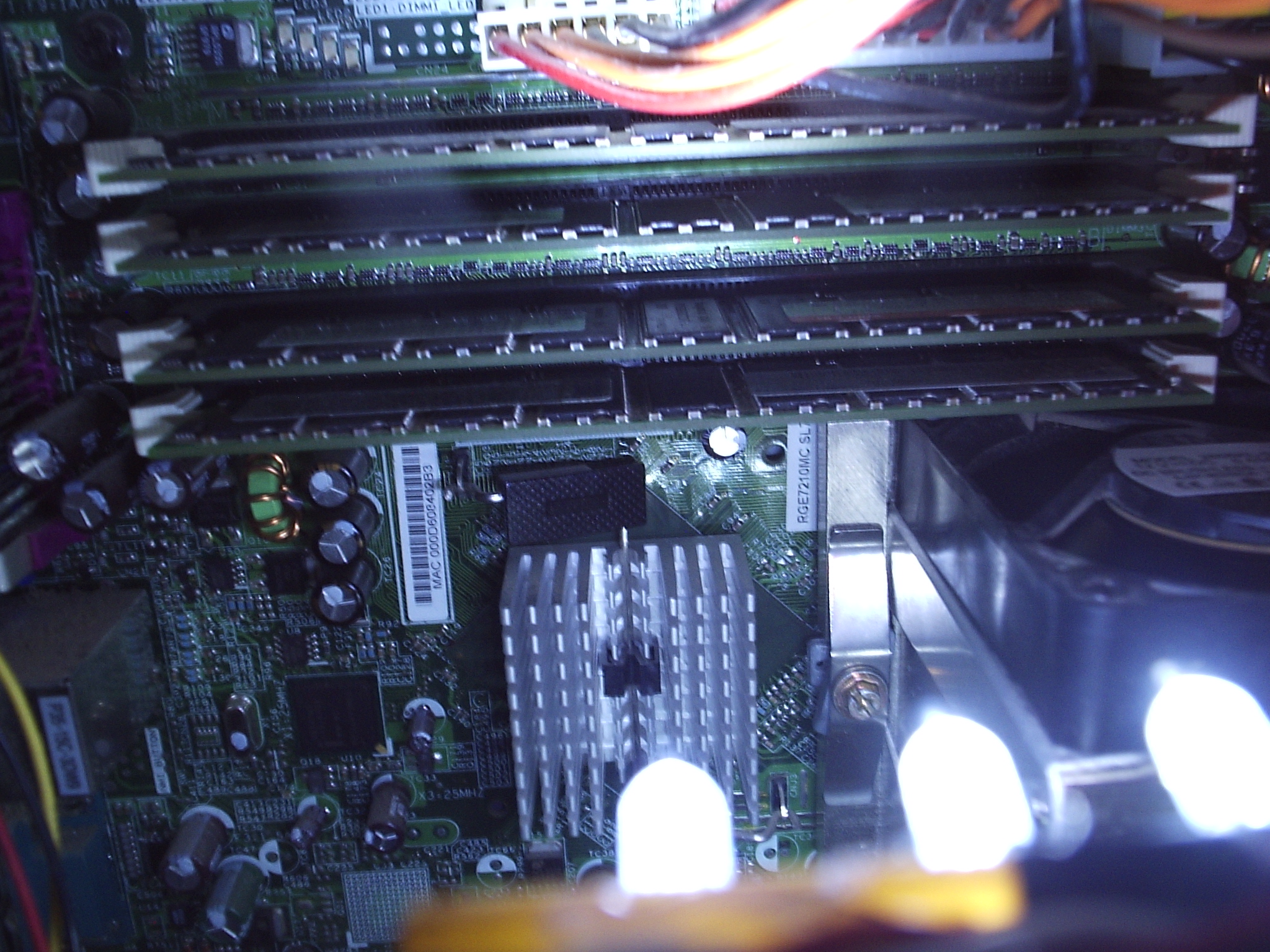
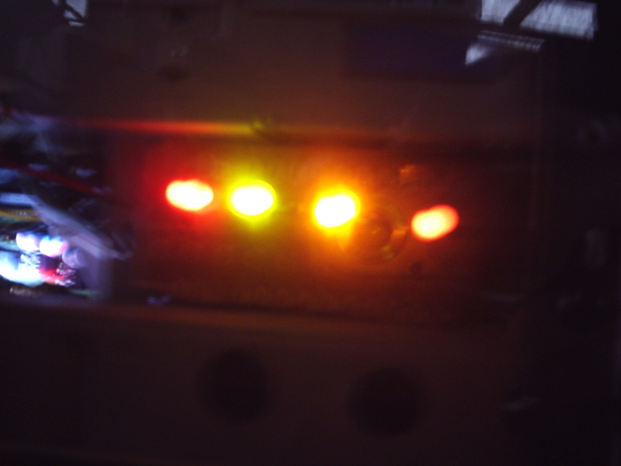
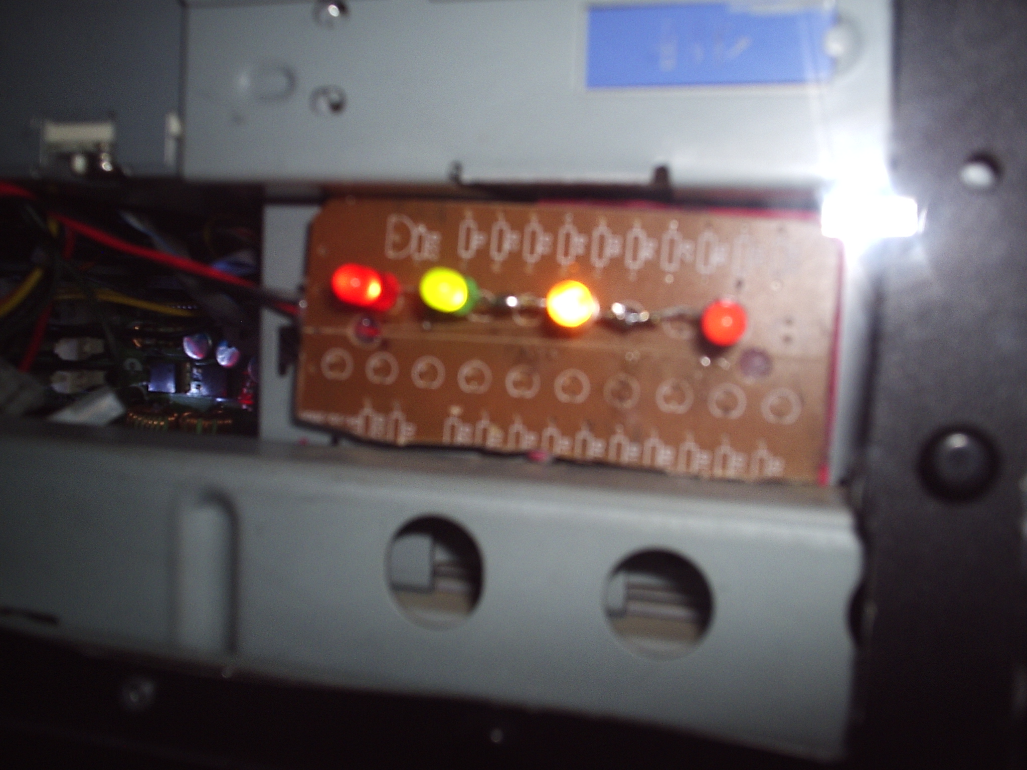
Here are some pictures of what your PC will look like with the interior illuminated by this lighting module.
Remember if you want I can build one of these for you. I can customize it in almost any way you want. I could even make it with blinking LEDs. PM me or check out this link:
https://www.instructables.com/community/Custom-Built-LED-Module-for-Your-PC/
Feel free to post any comments, questions, or suggestions in the comments section below.
If you think this is worthy you might cast me a vote in the shopbot challenge.
Enjoy.