LED Hat Display With Pong
A while ago, as my first microcontroller project, I made a Pong game on a 5x7 LED display, but then nothing became of it. Recently I was given a hard hat as part of a uniform (for an engineering competition) and told to customize it, and remembered pong.
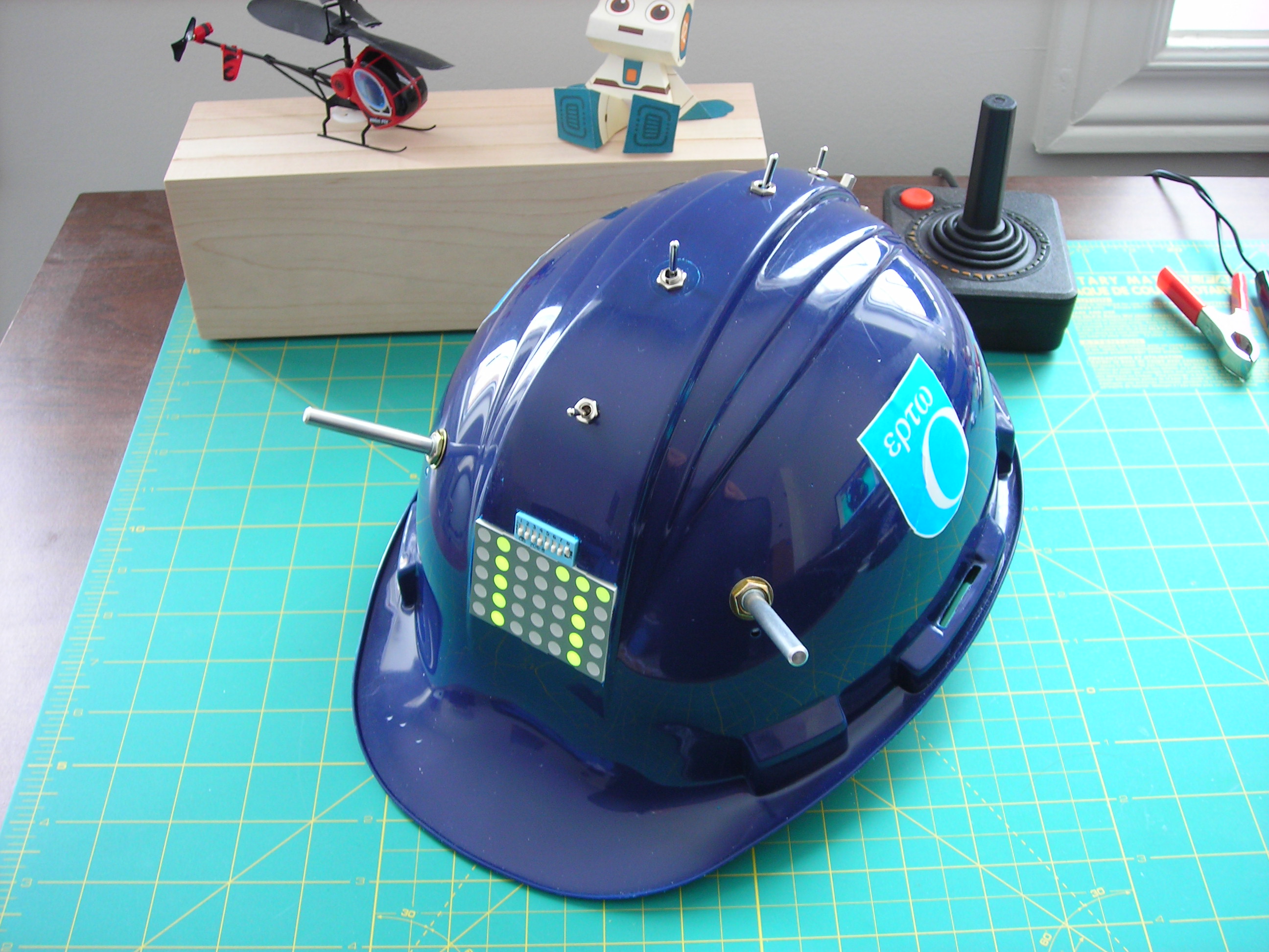
In this instructable I will show you how to make a scrolling LED display and how to install it in a hard hat. It also plays pong!
In this instructable I will show you how to make a scrolling LED display and how to install it in a hard hat. It also plays pong!
Downloads
Materials
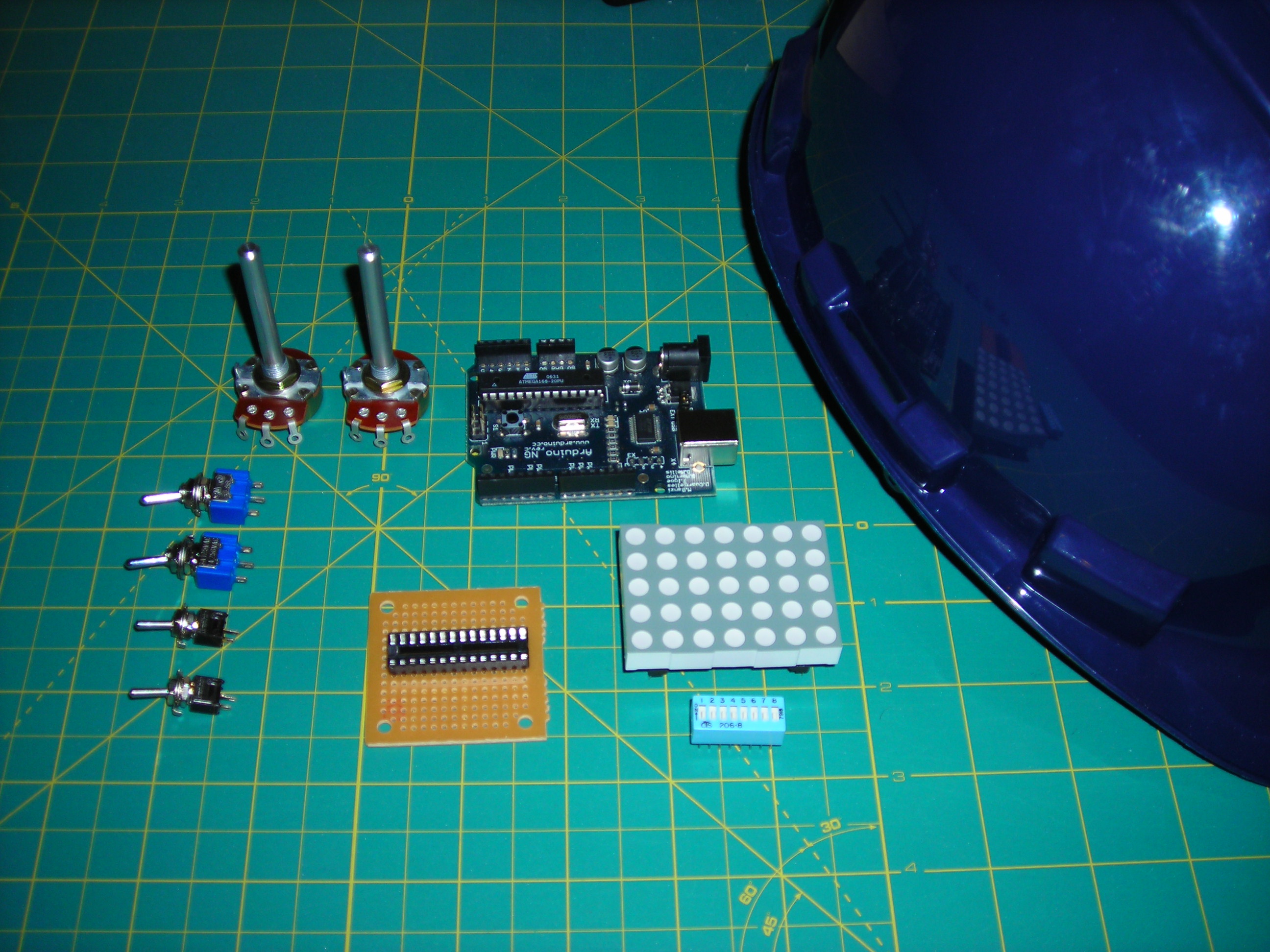
Parts:
-2 10k potentiometers
- 3 4.7 kOhm resistors
-4 SPST toggle switches
-1 5x7 bicolour LED display
-1 8 pin dipswitch
-1 Hardhat
-1 atmega168 microcontroller (or arduino)
-1 28 Pin 'skinny' socket
-1 breadboard
-1 3.7V lithium polymer battery
-Wire
-Solder
-Hot Glue
Tools:
-Soldering Iron
-Hot Glue Gun
-Wire Stripper
-Hobby Knife
-Plexiglas Cutting Knife
- Microcontroller Programmer (optional)
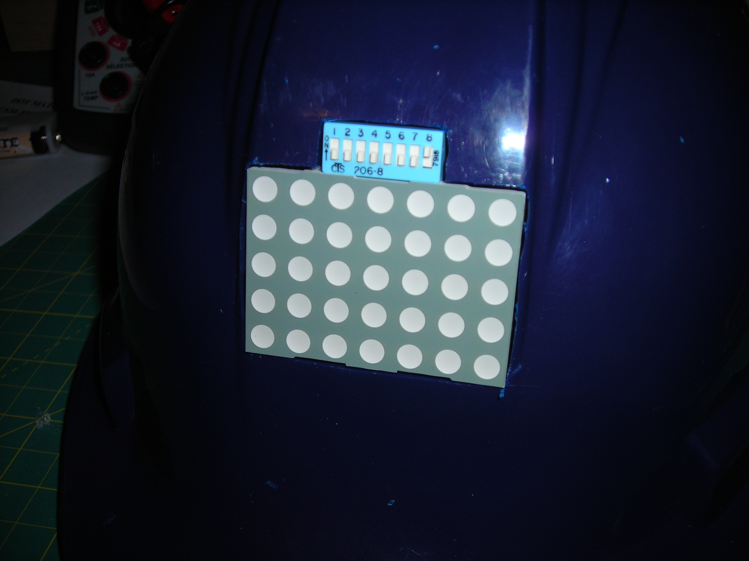
Solder the Display
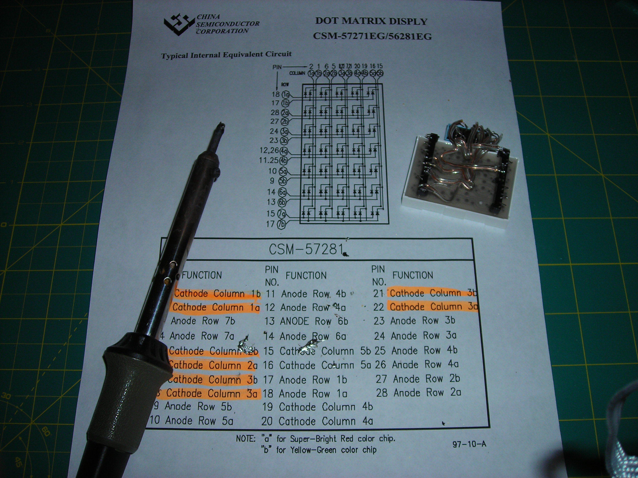
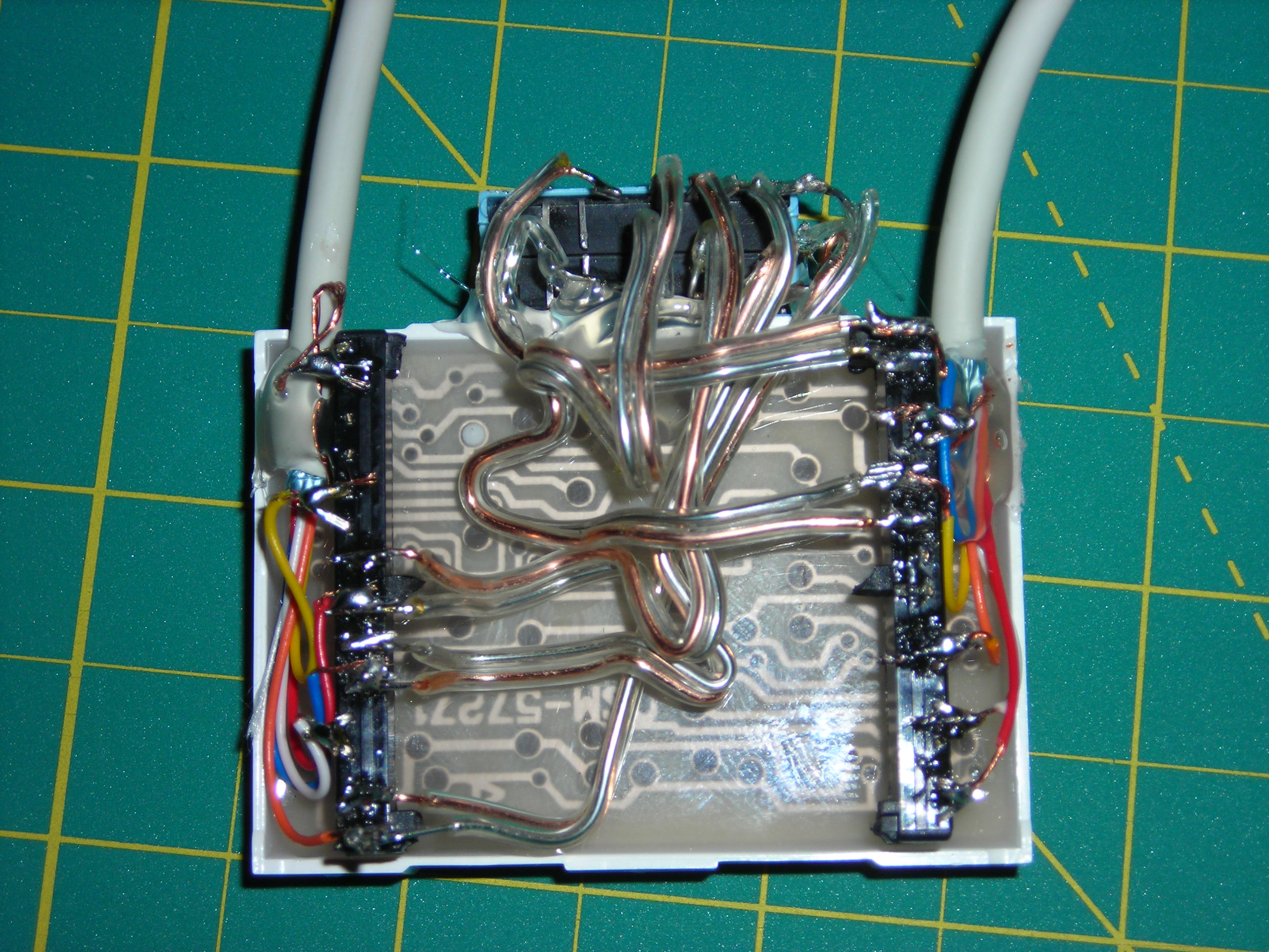
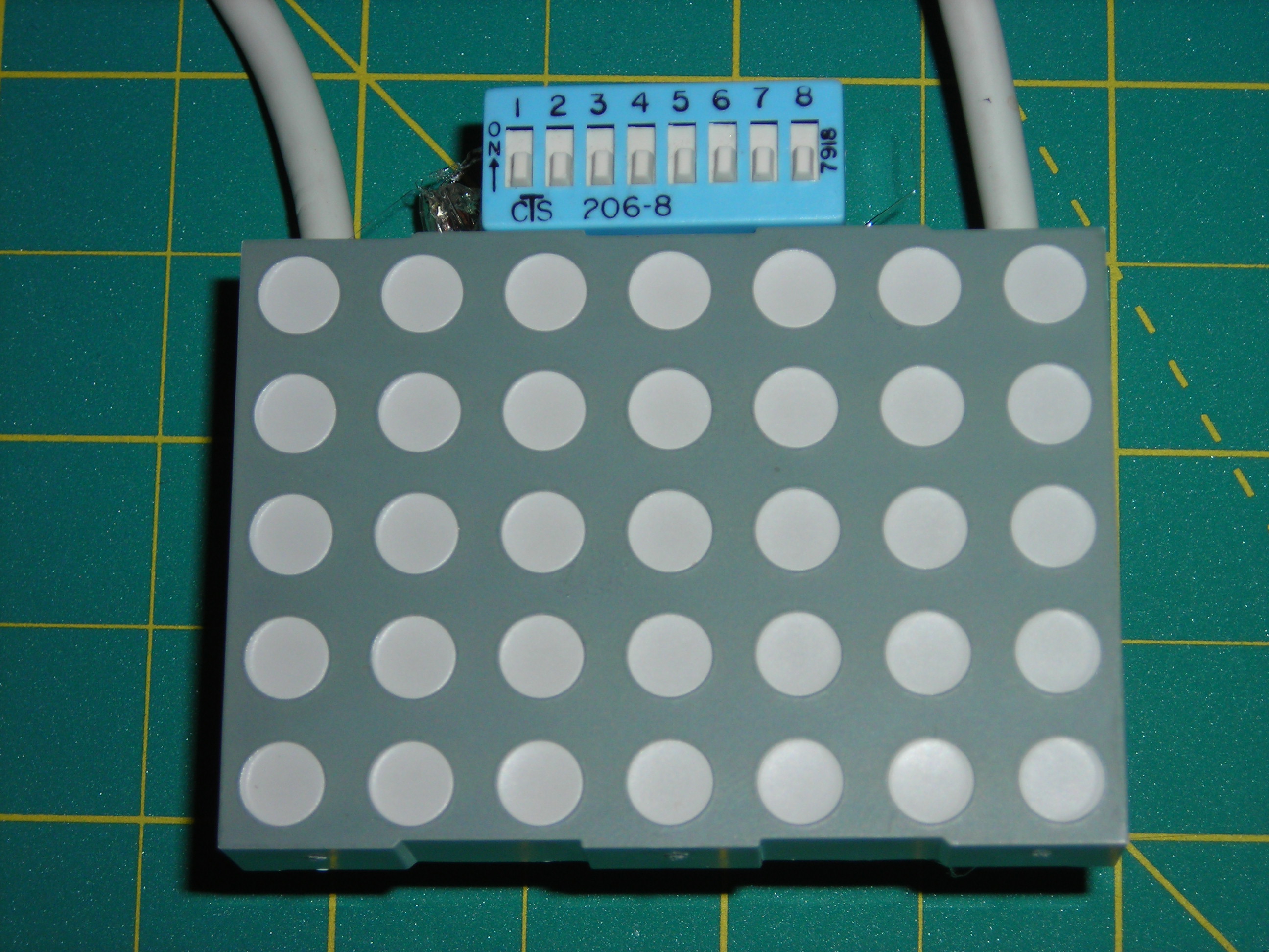
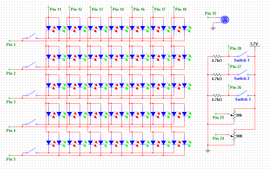
For the first step, you need to solder wires to the display. You will also need to solder one switch from the dip switch between the two colours' cathodes for each row. To make it clearer I have attached a schematic of the display in the pictures (click the [i] on the picture to get the full sized version).
For the next step I used switch 8 for a 'travel mode'. This is so the hat isn't accidentally turned on in a bag and drained.
For the next step I used switch 8 for a 'travel mode'. This is so the hat isn't accidentally turned on in a bag and drained.
Solder the Power Connections
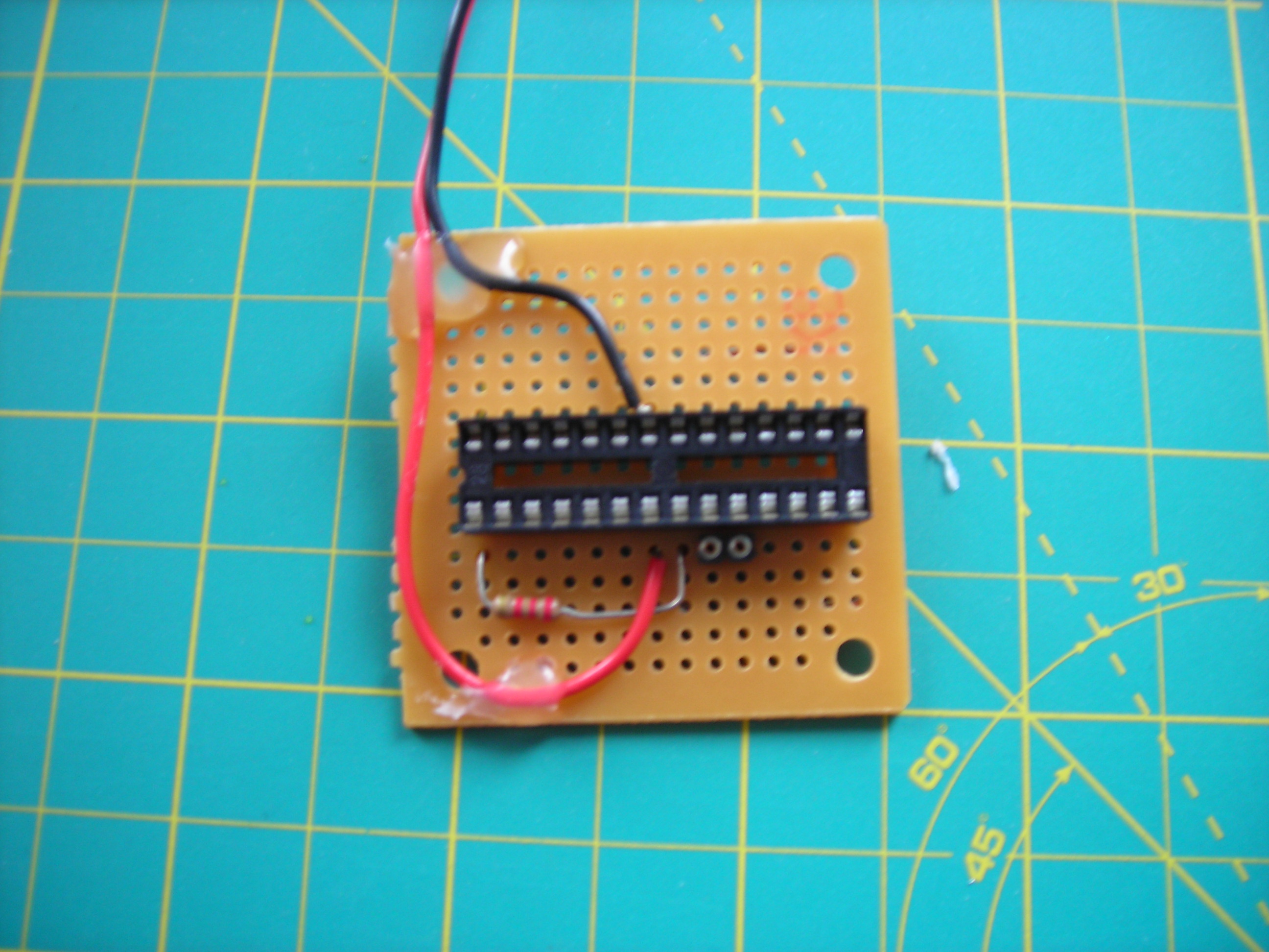
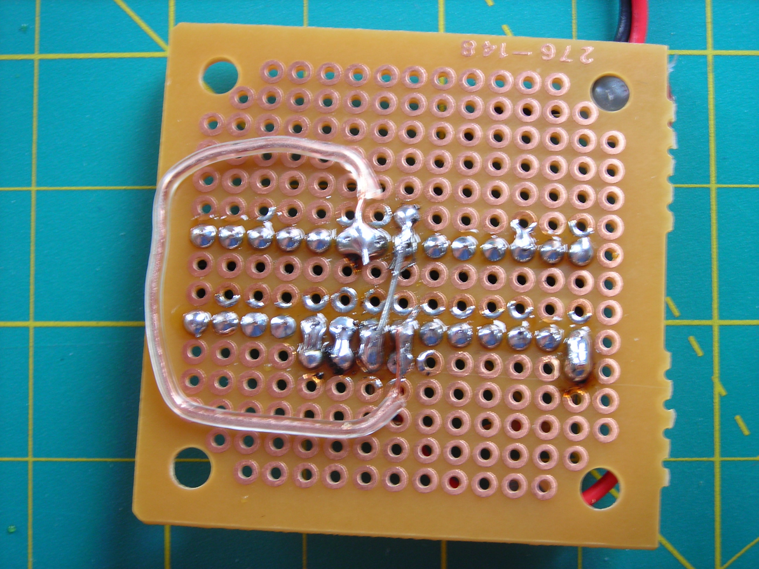
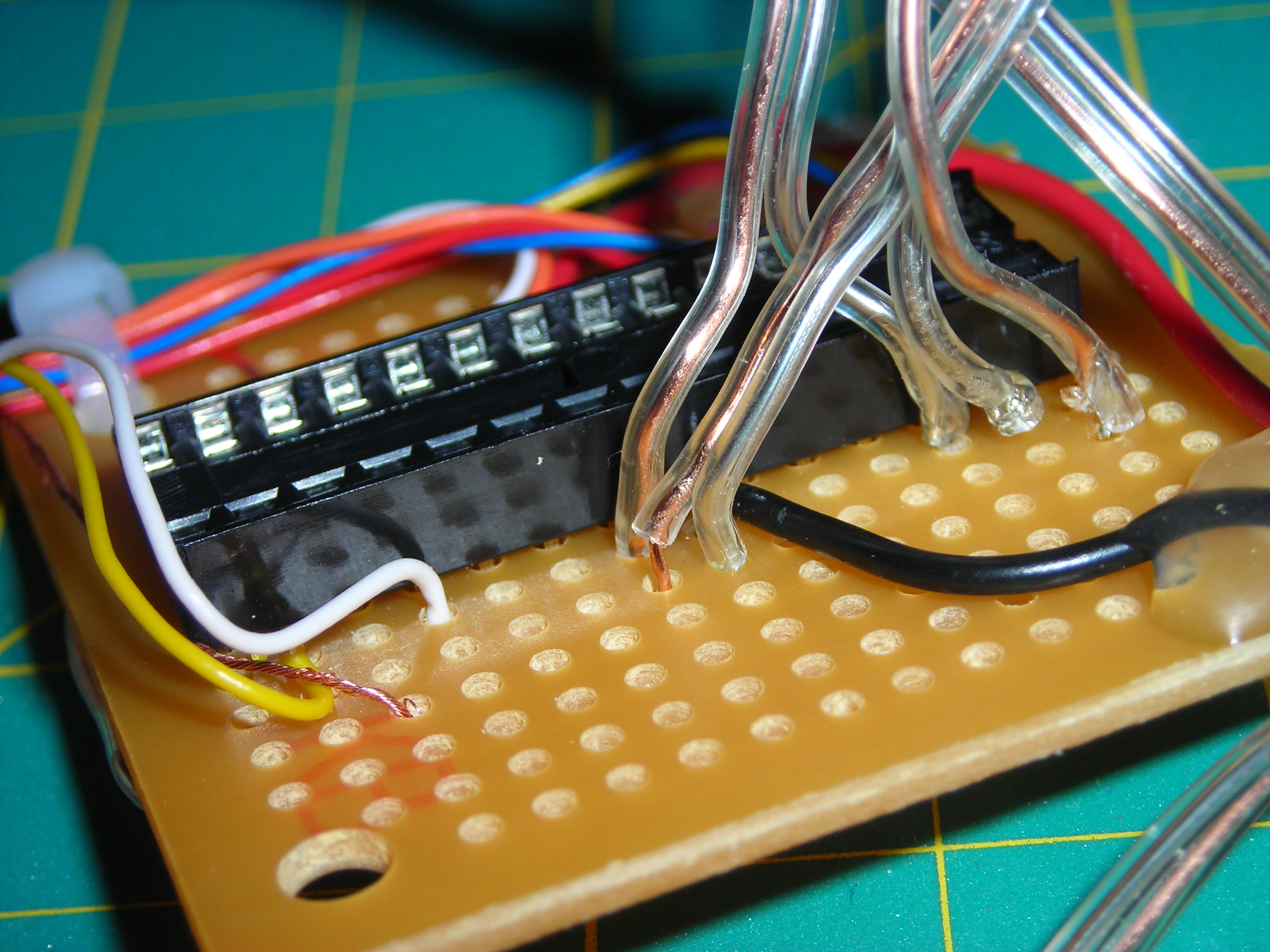
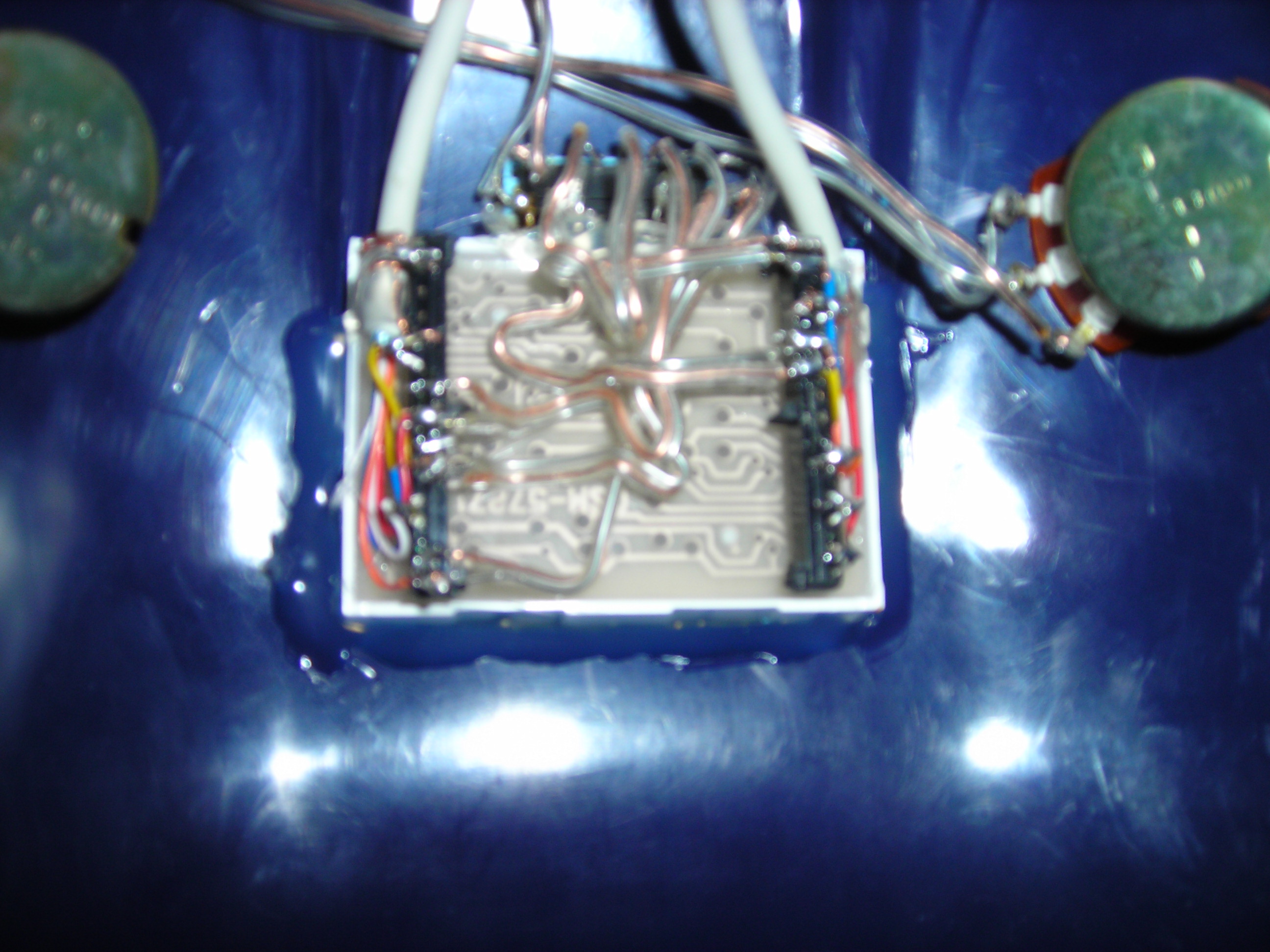
For this step you need to solder the microcontroller socket to the breadboard. Then solder all of the power connections to the microcontroller socket pins. If you are unsure which pins to solder, there is a good reference here.
Attach the LEDs to the Board
Now you need to attach the wires coming off the LED display to the breadboard. To help with this see the attached schematic, or you can look in the code in the intro to find the output pins on the arduino.
Solder Switches
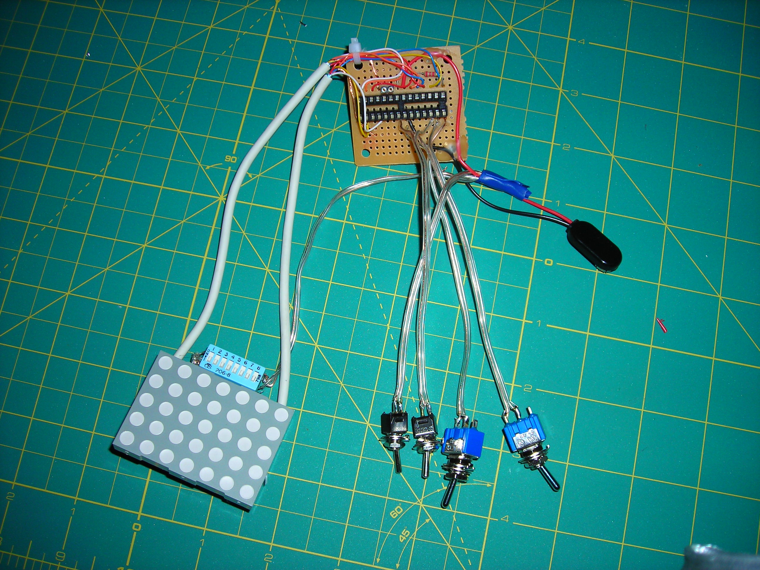
Next solder the switches to the breadboard. I have again attached the schematic in the pictures of this step.
For each switch, it is one contact of the switch connected to the corresponding microcontroller pin and the other to the positive voltage. There is also one resistor from the input pin to ground for each switch.
For each switch, it is one contact of the switch connected to the corresponding microcontroller pin and the other to the positive voltage. There is also one resistor from the input pin to ground for each switch.
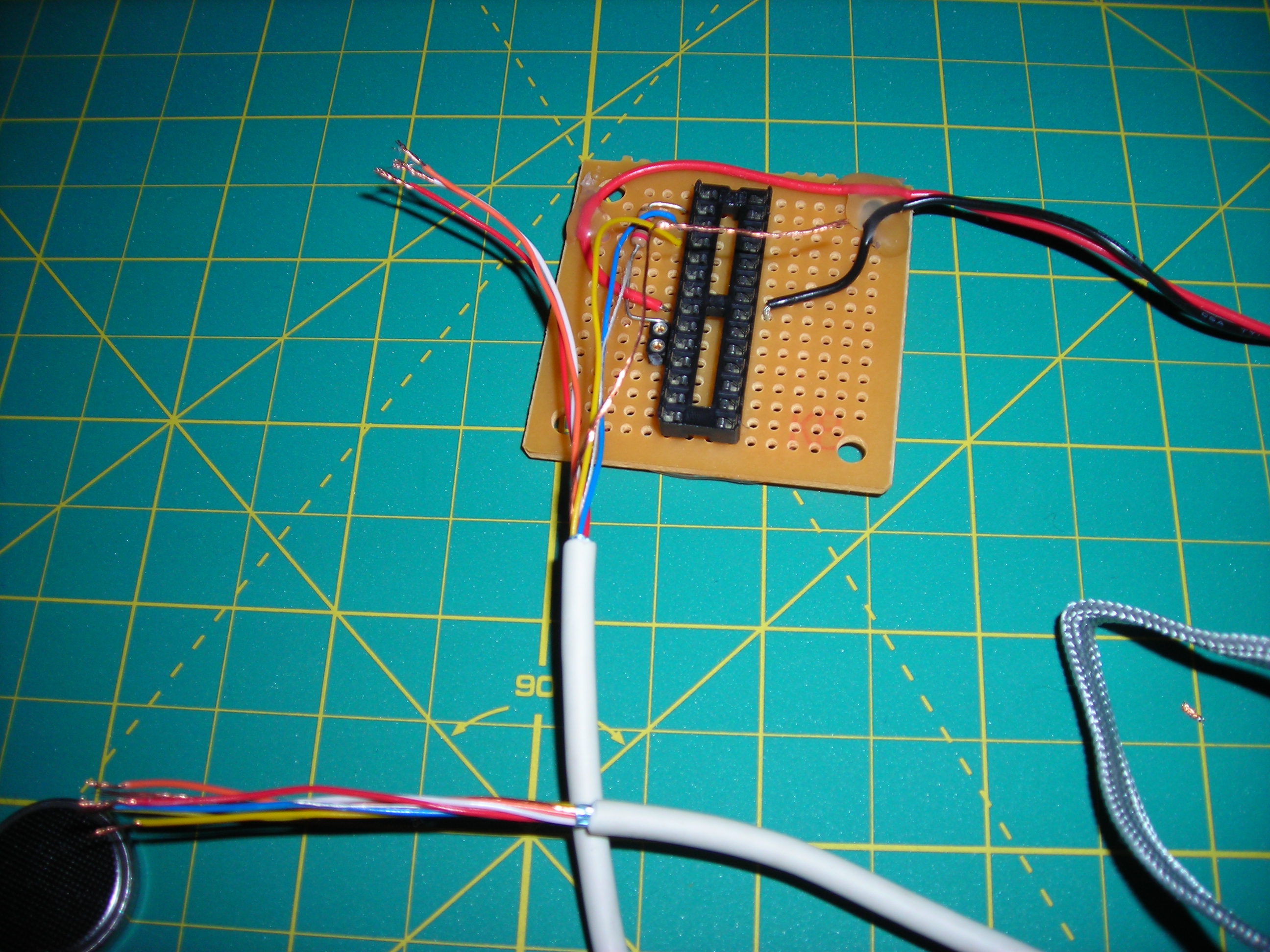
Solder the Potentiometers
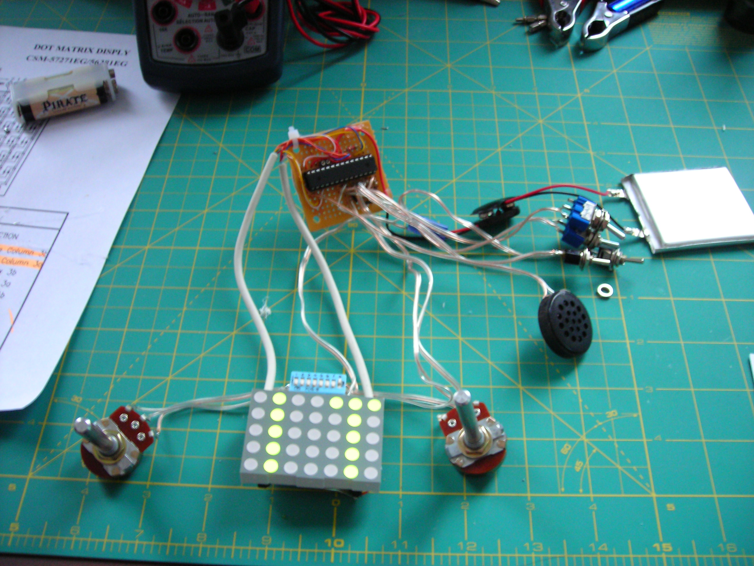
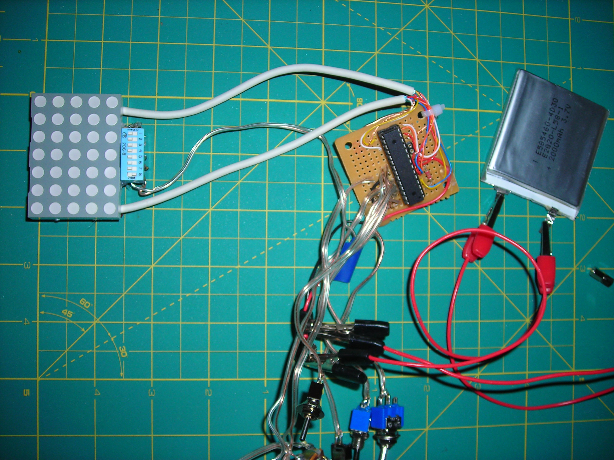
To solder the potentiometers, first solder the positive power to one of the outside leads (each pot has 3 leads, one for each end of the resistor and one for the changeable middle). Solder the negative to the other outside lead and a wire going between the corresponding analog in on the microcontroller, and the middle lead. Do this for each pot.
What side you solder the positive and negative lead on matters, it affects what way you turn the pot to move the paddle up or down. The best way to figure what side to solder it to is to solder the positive lead on the bottom when the 3 pot leads face the display from the side they will be mounted on. Or just guess and change it later.
This is also a good place to solder the speaker, attach one side to pin 15 on the microcontroller and the other to ground.
Program the Microcontroller
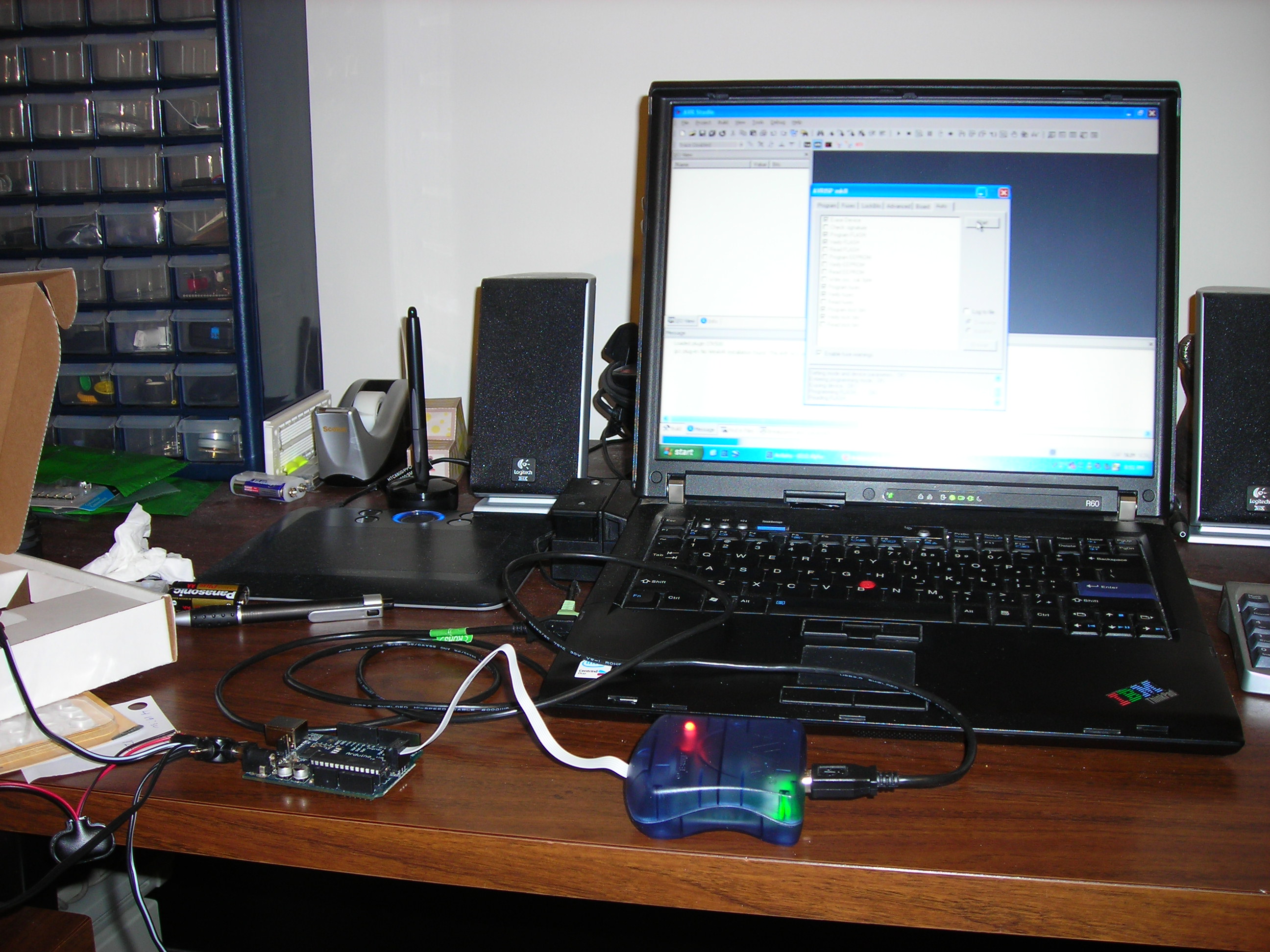
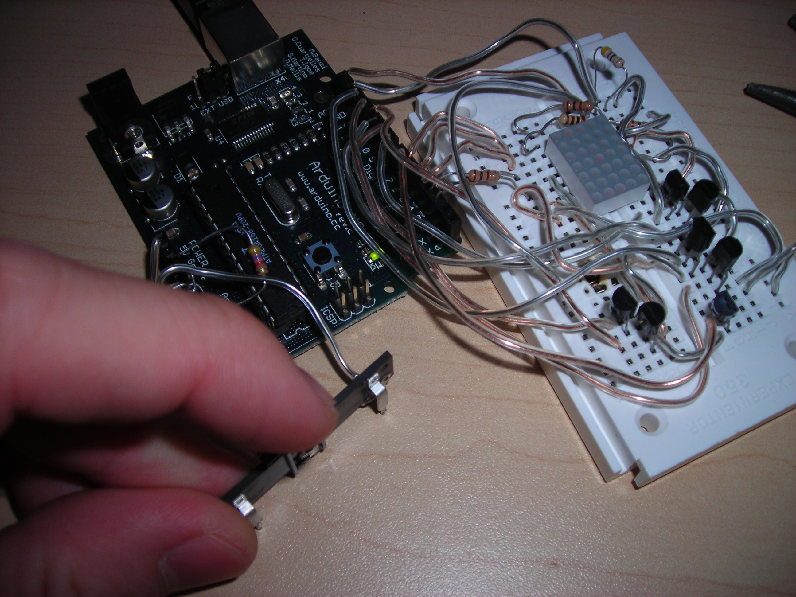
This can be the most daunting task if you are new to microcontrollers. The setup I use to program the microcontrollers using an AVRisp mkII to load the bootloader for an Arduino, which can be programmed over USB.
Load the program attached to this step (or in the intro) onto the microcontroller (the .hex file in the applet folder can be loaded onto the microcontroller in place of the bootloader). When burning the bootloader, set the chip to use the 8MHz internal crystal, unless you want to use an external crystal (the extra speed isn't really needed). If you do re-compile the code be sure it is at the correct clock speed for what you will be using.
Once it's programmed, put the chip into the socket on the breadboard.
Downloads
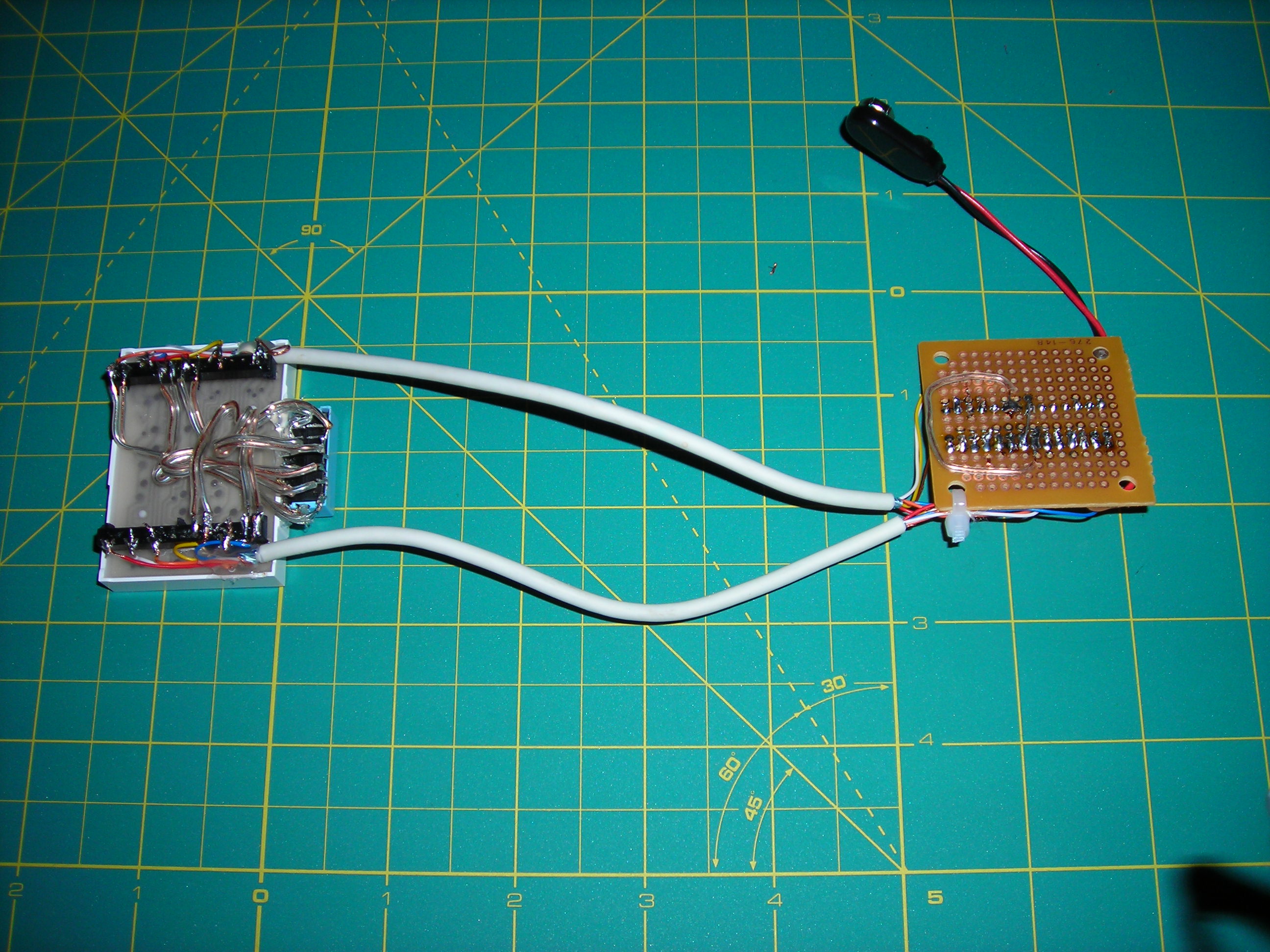
Testing and Debugging
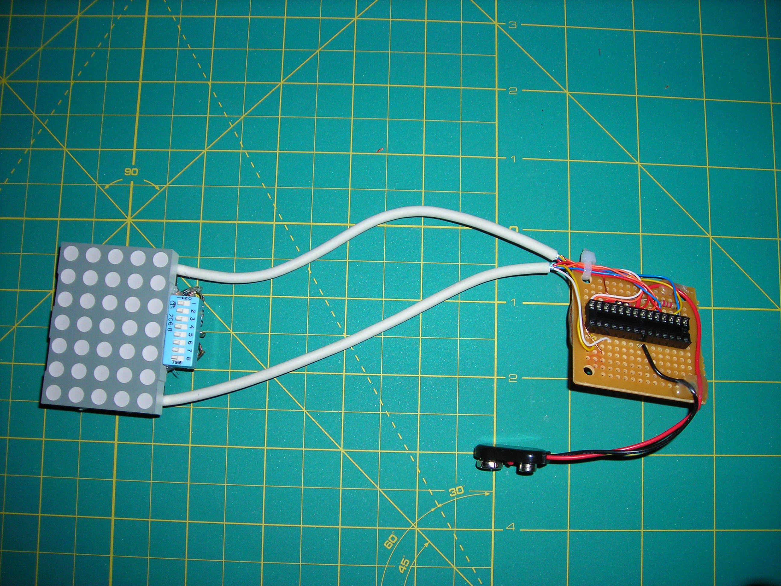
Now is the time to connect the battery and hope it works.
If it didn't work, I'll try to give some debugging tips:
if a line is missing from the display, it is a loose connection or a shorted wire.
is nothing is happening, first check the power and the switches. If it is getting the proper voltage and still doesn't work (and the chip is plugged in the proper way), test all of the components one by one.
If it powers on, but the screen isn't displaying properly, ensure that you have the proper type of display, 5 cathode rows and 7 anode columns (the labeling of the rows and columns can vary from data sheet to data sheet).
If it still doesn't work, leave a comment and I will try to help.
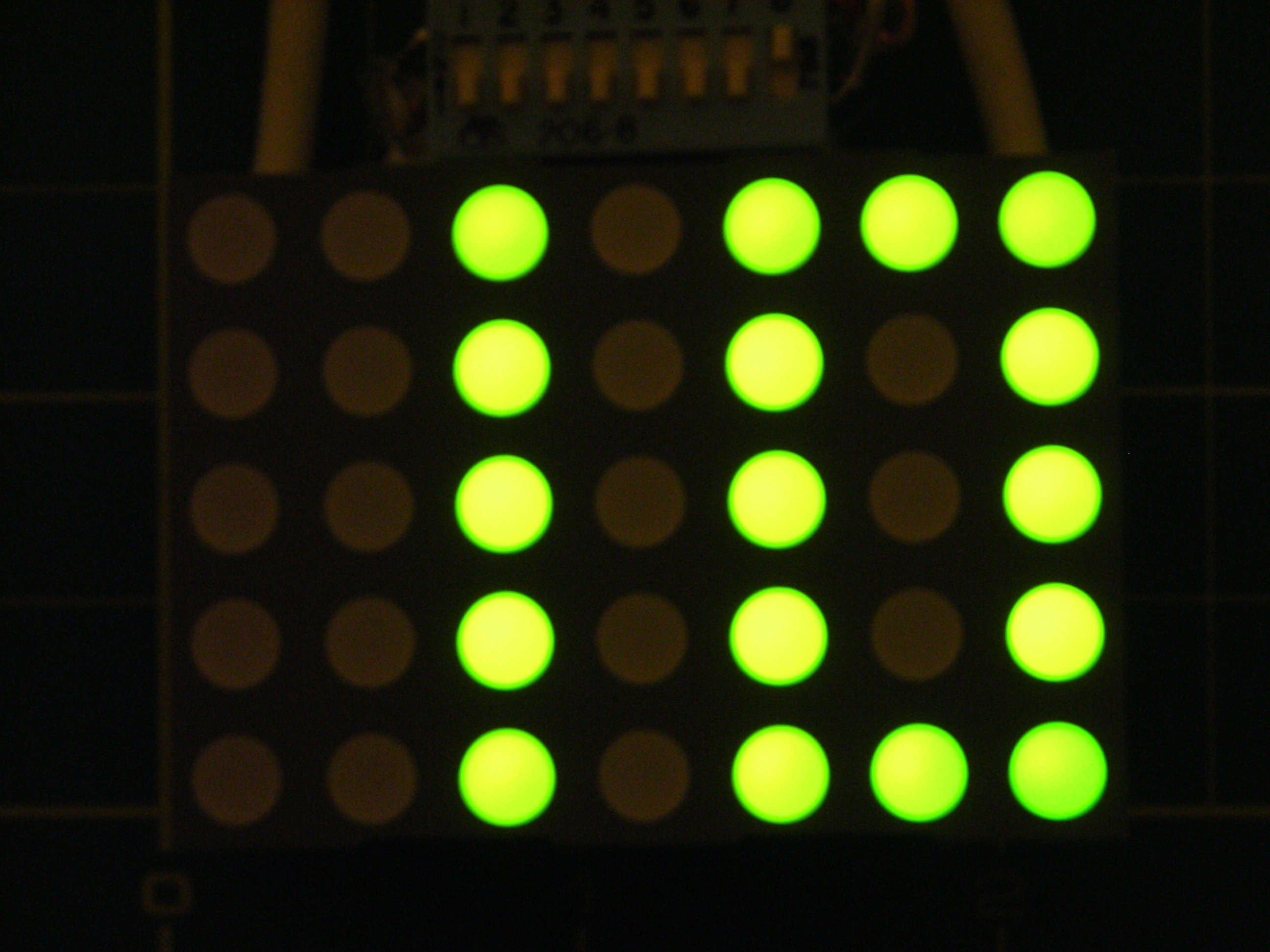
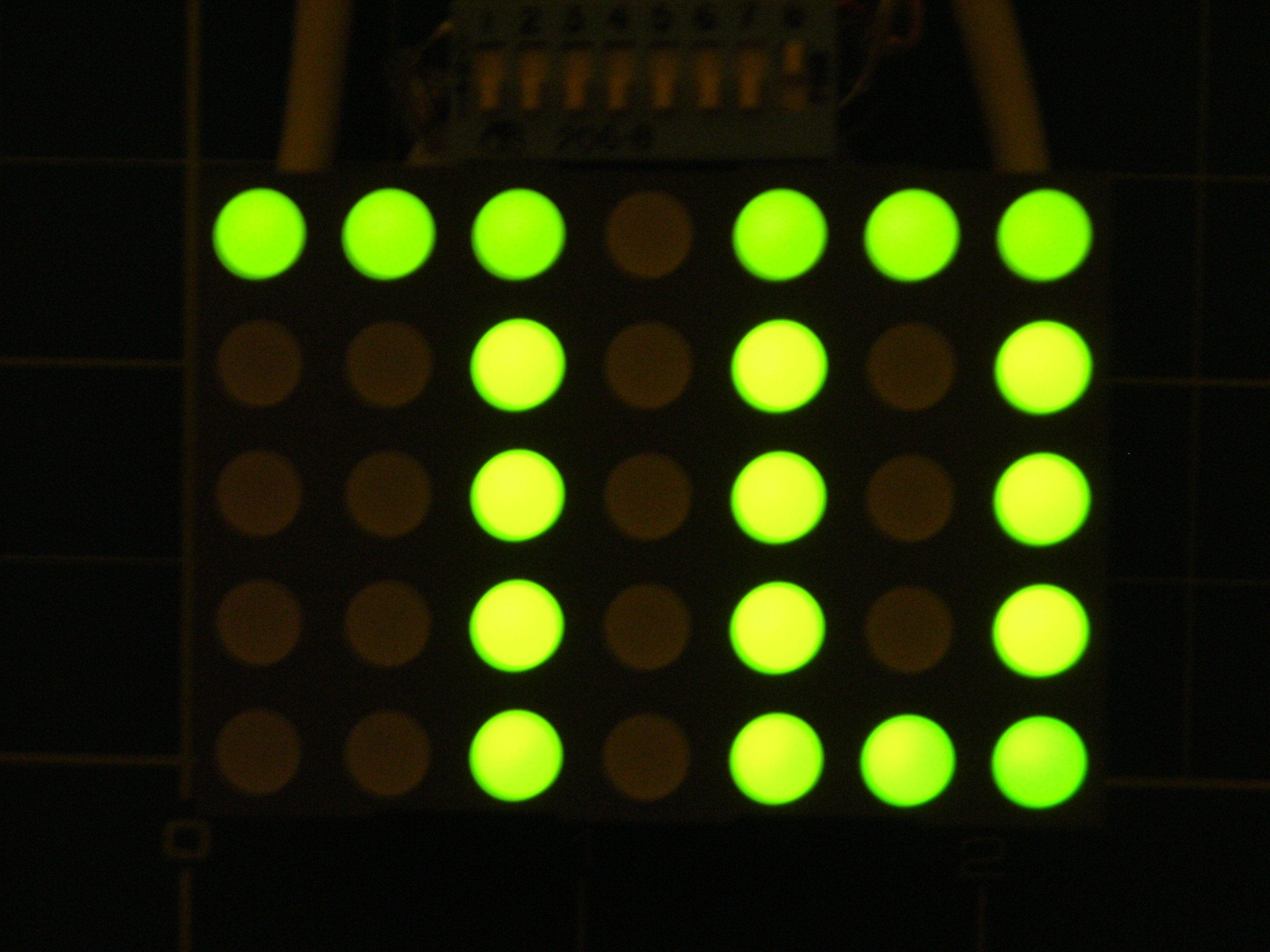
Operation
Once it is on, flip switch one to switch between Pong and the display mode.
In display mode it will show UOIT (my university) and if you flip switch 3 it will show ERTW (bonus points of you figure this one out).
In Pong mode, turn the potentiometer to move the paddles. Flip switch 2 to change from 1 player to 2 player and if you are finding it too easy, flip switch 3 to speed it up.
Prepare the Hat's Display Hole
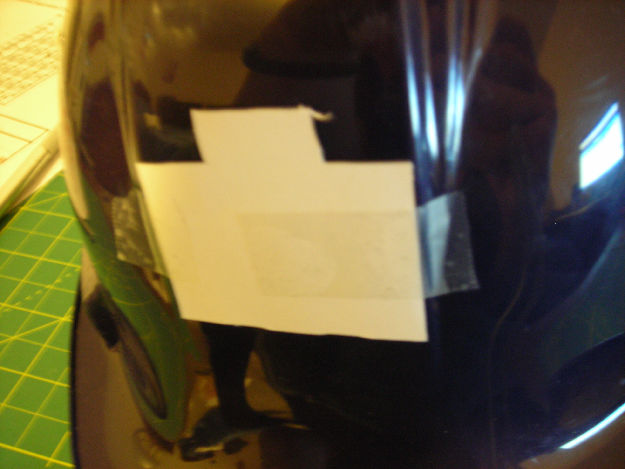
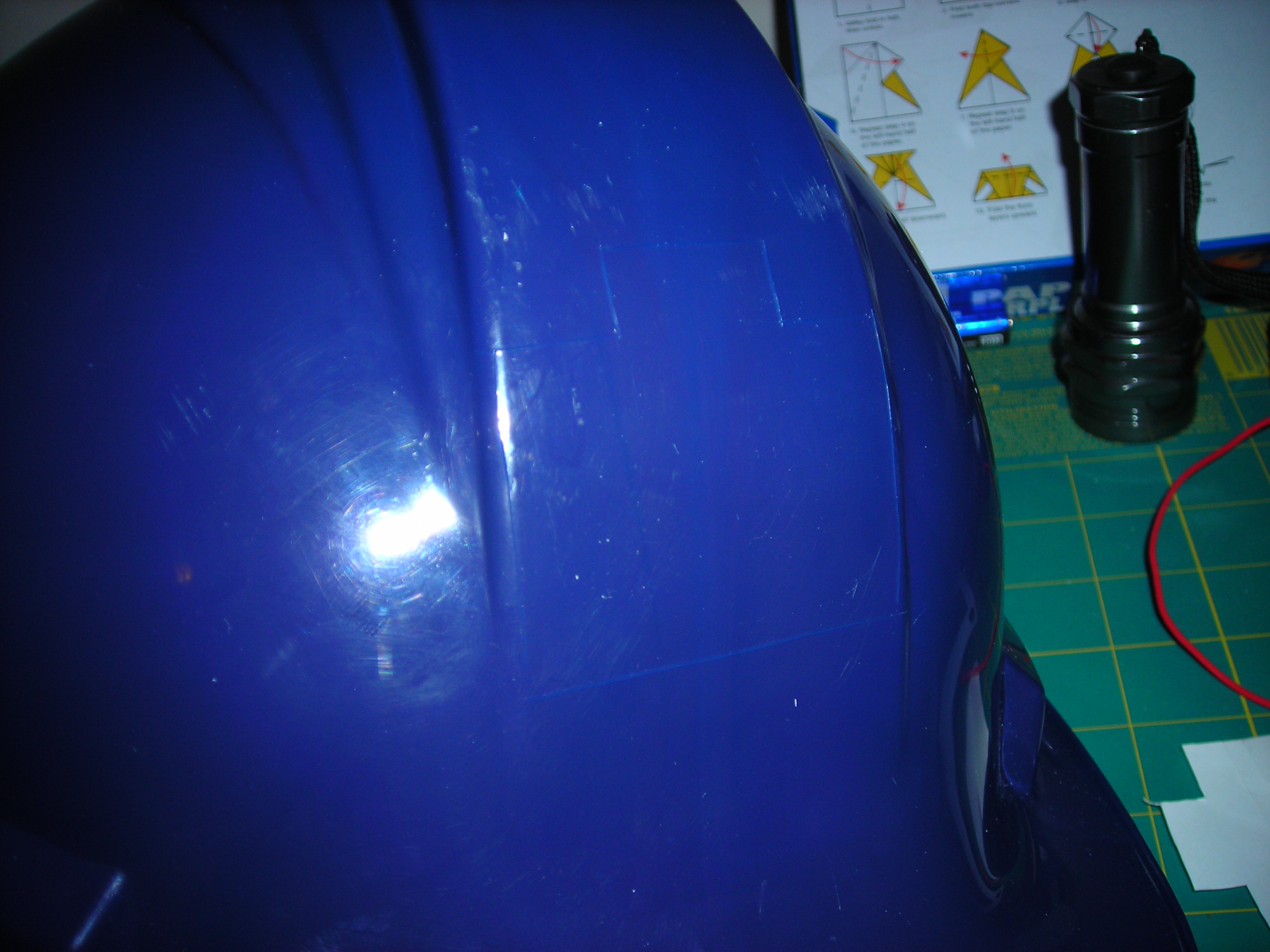
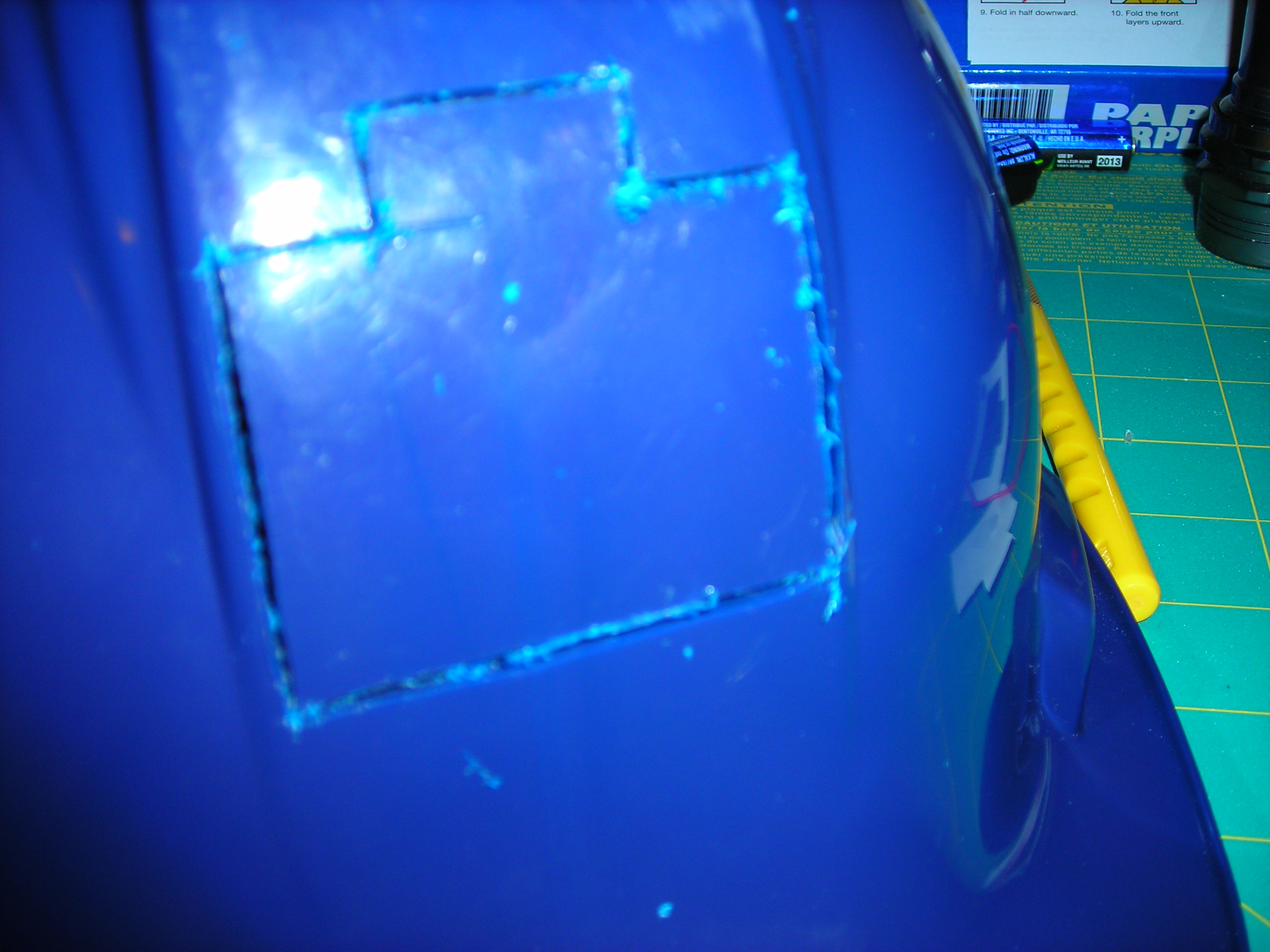
This is the first step in installing the electronics in your hat.
Start by tracing a template of the display and cut it out. Tape the cut-out to the hat where you want the display to go, then trace it with the hobby knife. Be vary careful at this part, it is easy to slip when cutting hard curved surfaces. Now with the outline on the hat, take the plastic cutting knife and trace along the lines until you poke through. Now finish the hole by cutting out the remaining joining plastic with the hobby knife.
Start by tracing a template of the display and cut it out. Tape the cut-out to the hat where you want the display to go, then trace it with the hobby knife. Be vary careful at this part, it is easy to slip when cutting hard curved surfaces. Now with the outline on the hat, take the plastic cutting knife and trace along the lines until you poke through. Now finish the hole by cutting out the remaining joining plastic with the hobby knife.
Drill the Switch Holes
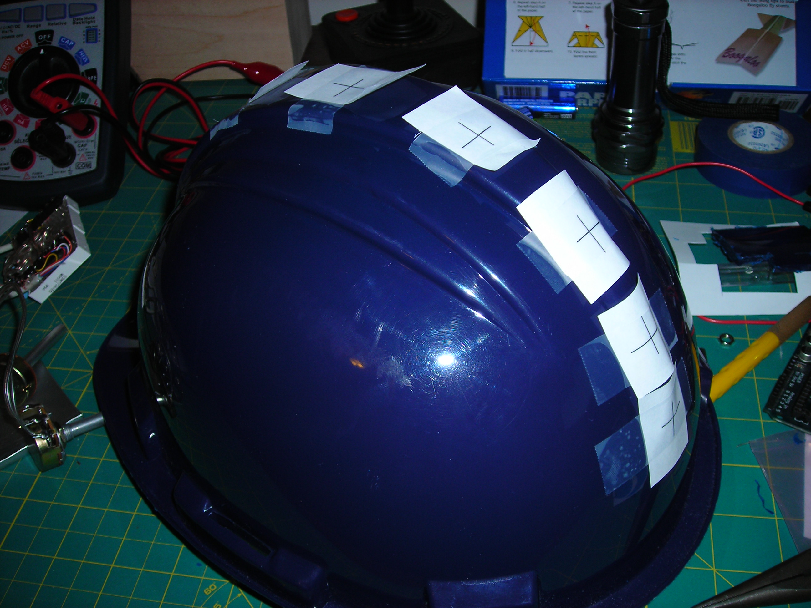
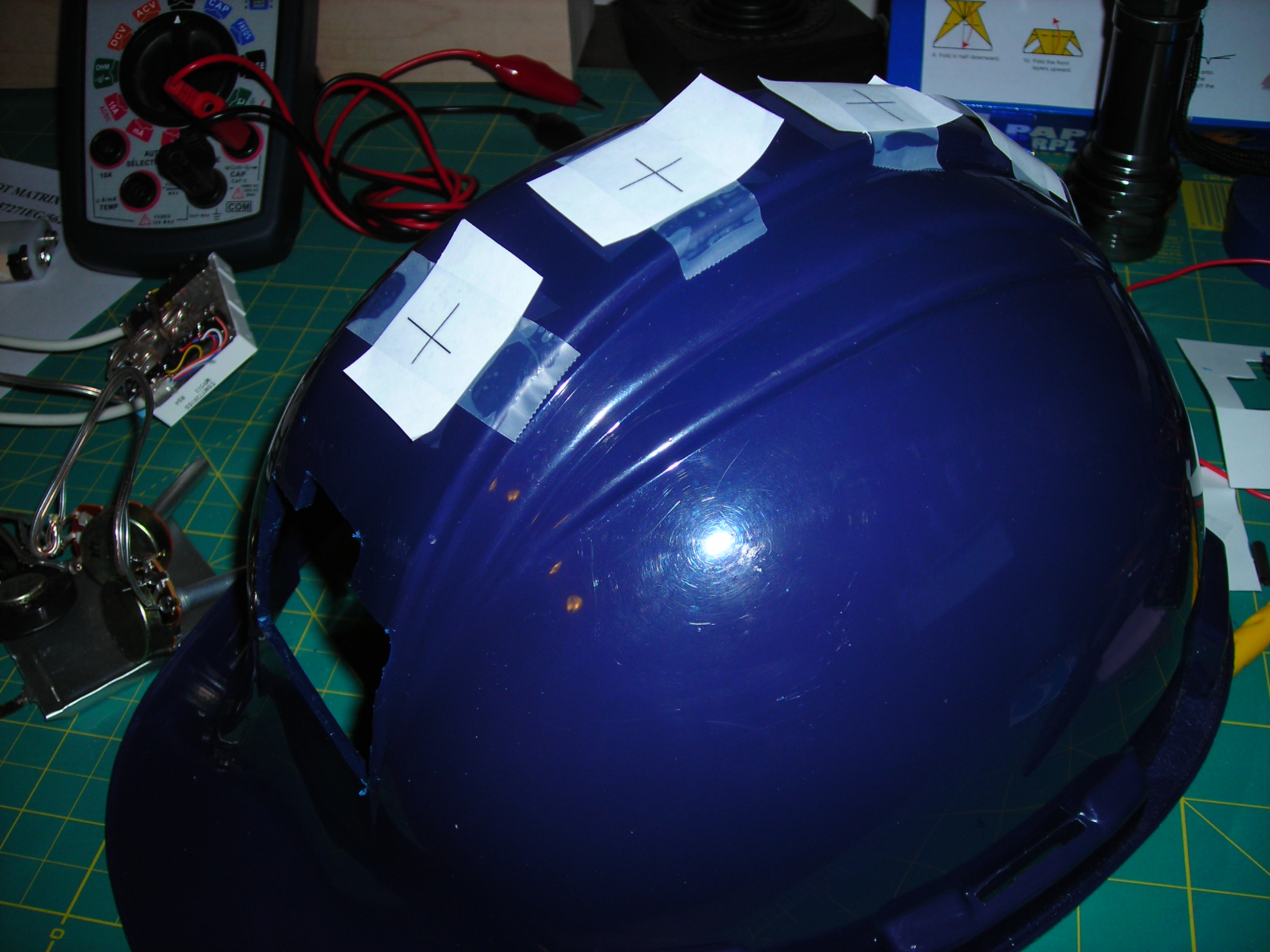
I placed my switch holes down the center like a short metal Mohawk, but you can place them wherever you like.
Start by making small Xs, one for each switch and accessory. Tape these to the helmet with the middle of the X where you want the hole.
Now select the appropriate drill size and drill each hole.
Start by making small Xs, one for each switch and accessory. Tape these to the helmet with the middle of the X where you want the hole.
Now select the appropriate drill size and drill each hole.
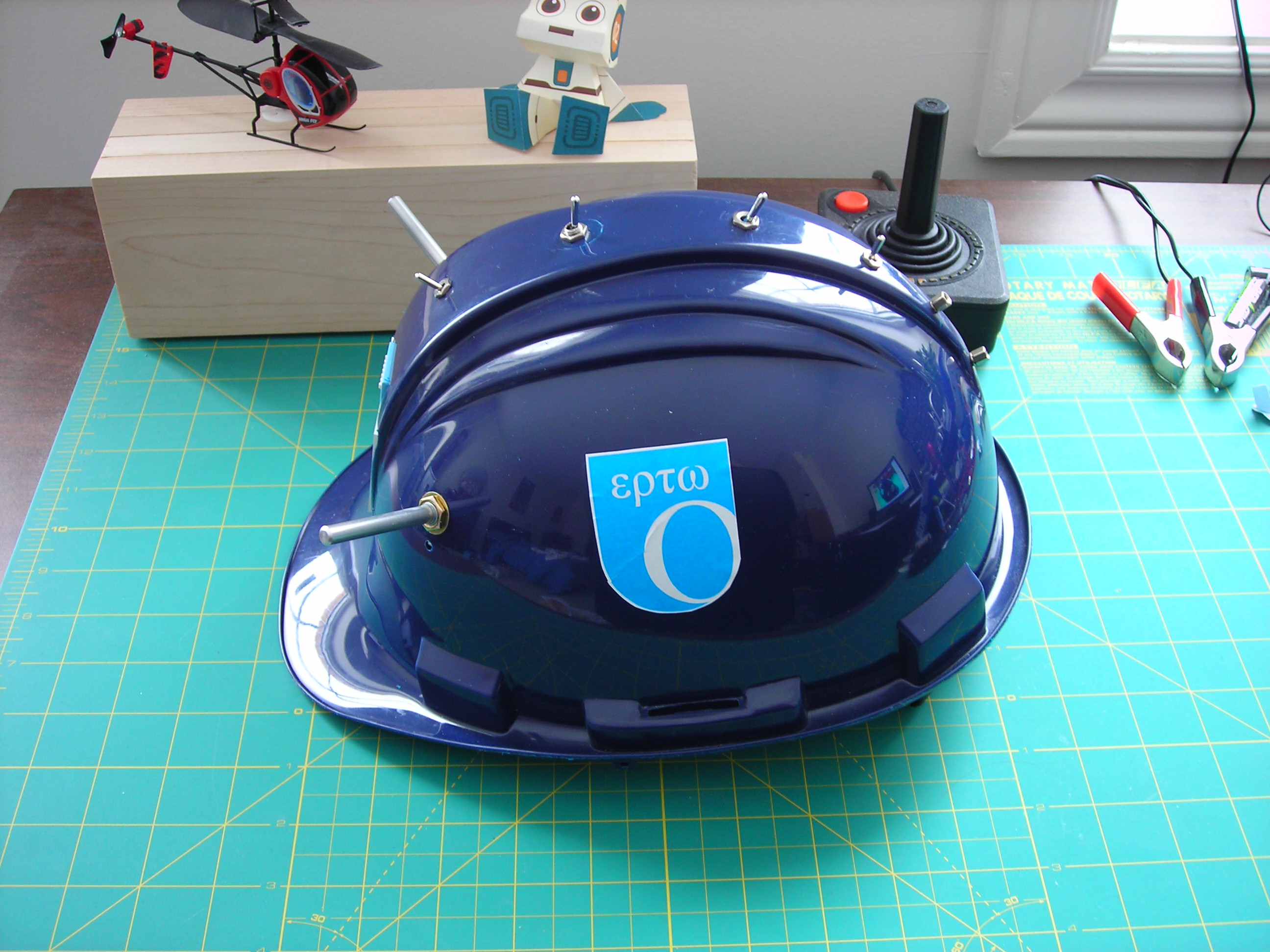
Finish the Hat
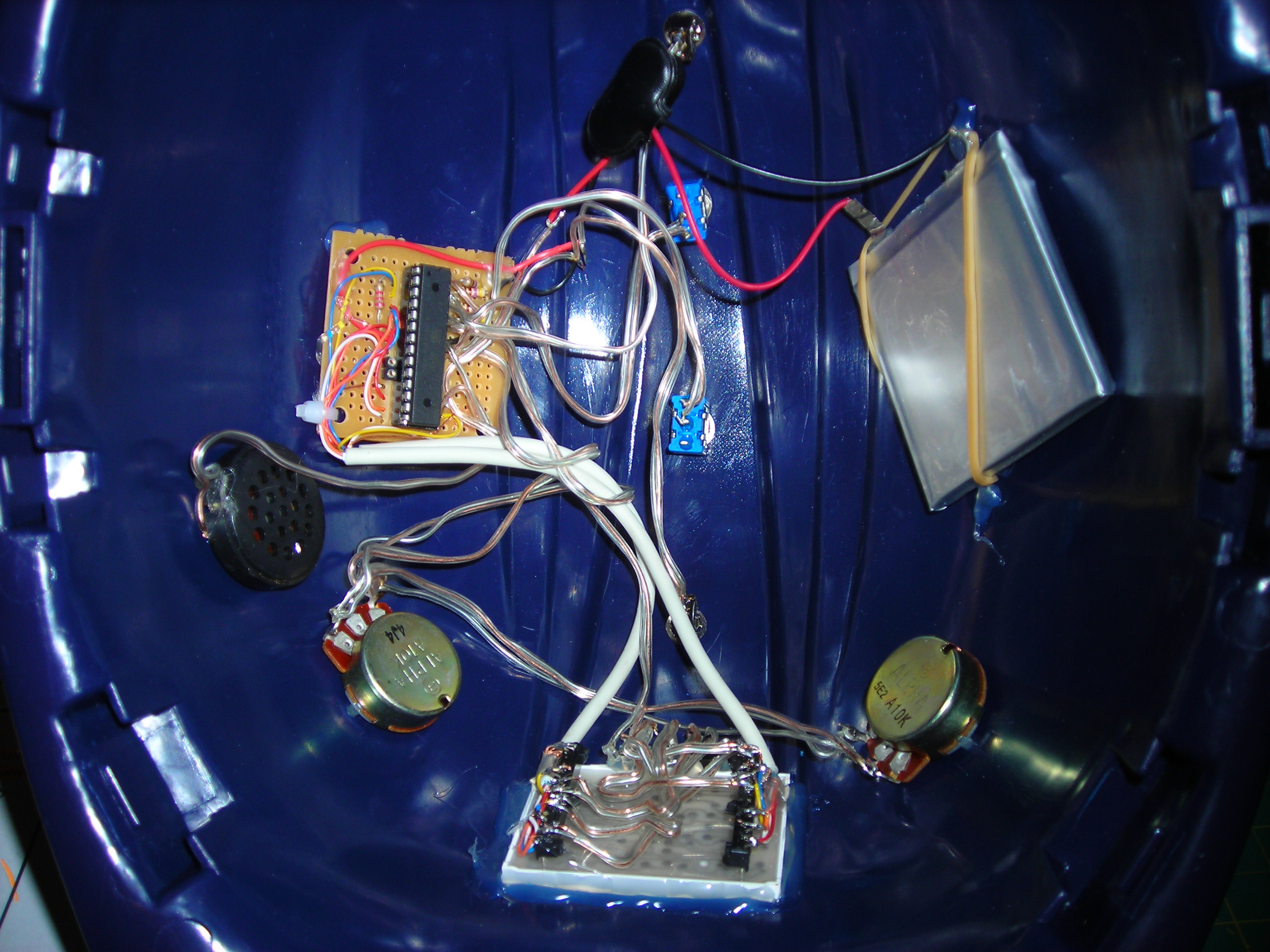
The final step is to install all of the parts in the corresponding holes, and apply hot glue as necessary to hold the parts in place. I have put notes in the photos for more pointers.
All that is left to do is show it off!
Since you've read this far, you must be at least interested, so please rate it!
All that is left to do is show it off!
Since you've read this far, you must be at least interested, so please rate it!