LED Guess-O-Matic
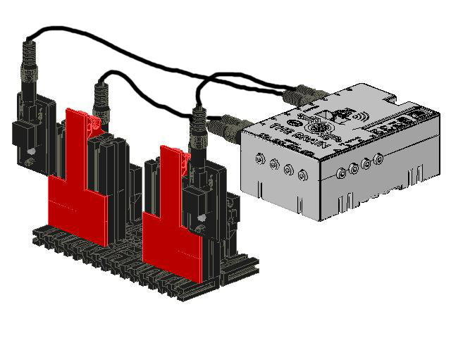
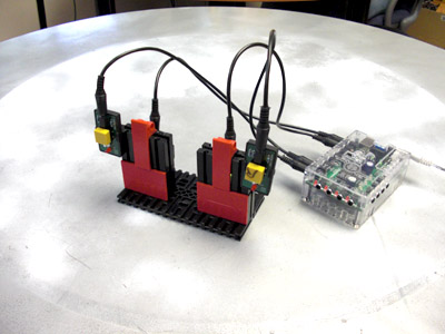
How to create the fischertechnik LED GUESS-O-MATIC GAME:
I play with different educational manipulatives for a living. (Visit www.weirdrichard.com).
An easy-to-build application is the LED GUESS-O-MATIC GAME. The robotic controller (in this case the PCS BRAIN) randomly selects one of two LED to light. The LEDs are hidden behind mounting plates. Next to each LED is a push button. Guess which LED is lit by pressing one of the switches. If your guess is correct, the controller plays a happy tune! Guess incorrectly, and you receive a single beep.
This instructable will describe how to create a fischertechnik LED GUESS-O-MATIC GAME!
Note: The images were generated by a CAD program and a fischertechnik elements library.
Gather Elements:

You will need to gather your elements. The fischertechnik elements are available from a range of kits available from ebay, Craig's List, or fischertechnik retailers.
Elements can be purchased individually from www.fischertechnik.com.
The PCS BRAIN kit and electronic components can be purchased here:
http://edventures.com/imssc/nsimssc/index.php?&pid=12182
The PCS BRAIN kit and electronic components can be purchased in Germany here:
http://www.nwt-online.de/products_new.php?osCsid=16227515cbca6245b6280bbfacf08079
OR the controller and components can be replaced with similar items purchased elsewhere.
The Parts List:
2 Hinged Block Tab (#31426)
2 Hinged Block Claw (#31436)
4 Building Block 15 with Counterbore (#32321)
8 Building Block 30 (#32879)
2 Building Block 15 (#32881)
2 Building Block 15 with 2 Pins (#32882)
1 Base Plate 120x60 (#35129)
6 Mounting Plate 15x45 (#38242)
1 PCS BRAIN
4 Sensor Cables
Power Supply
2 LED Elements
4 Nuts
4 Bolts
4 Sensor Cables
2 Switch Elements
(A small screwdriver is useful to attach LED and TOUCH SENSORS to the Building Block 15s with Counterbores)
Add LEDs to Base
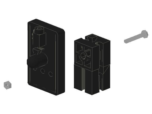
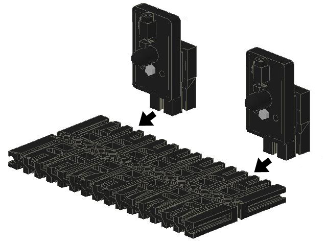
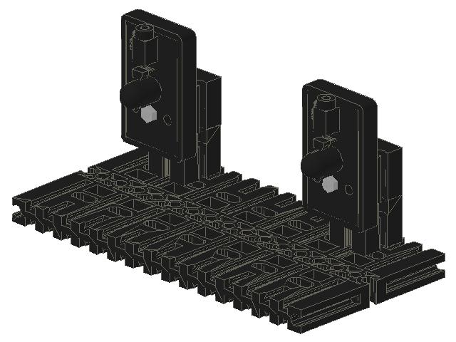
Fix two LED components to Building Block 15s with Counterbore using nuts and bolts. Slide each BB15 with Counterbore onto a Building Block 15, and insert the assemblies into the third slot from each end of the baseplate.
Create LED Covers
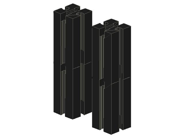
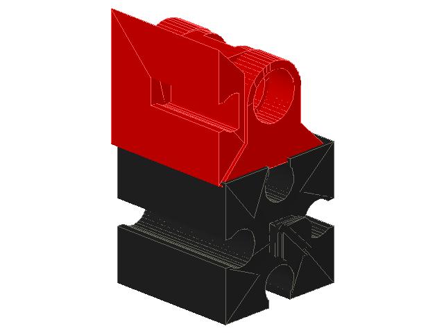
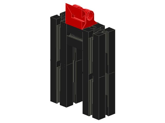
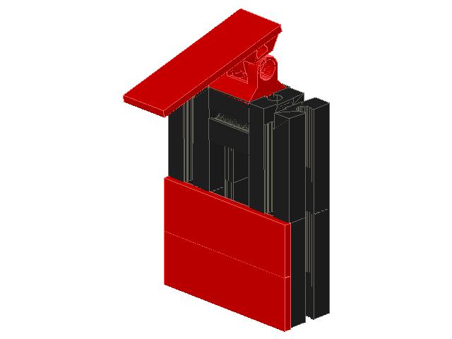
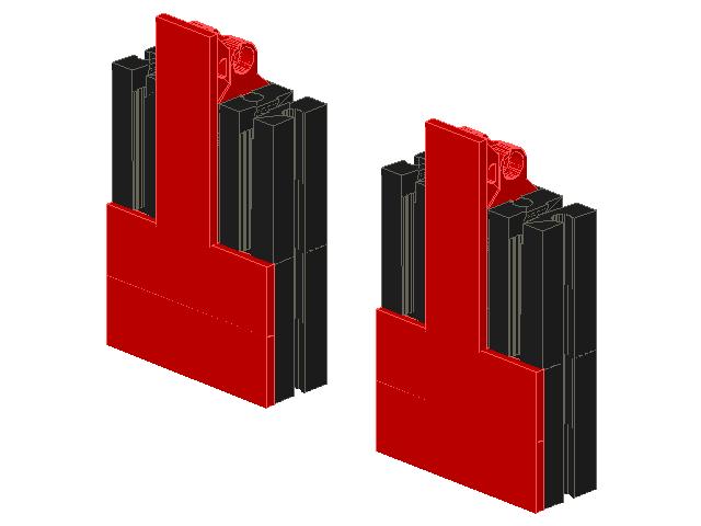
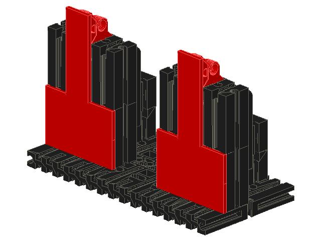
Create two stacks of two Building Block 30s. Insert a Hinged Block Tab to a Hinged Block Claw and fix onto a Building Block 15 with 2 Pins. Connect the two block stacks with the BB 15 with 2 Pins. Add two Mounting Plates 15x45 to the front face of the block stacks, and a third Mounting Plate 15x45 to the Hinged Block Tab. Make a second identical cover, and add to the baseplate, placed so that the covers are in front of the LEDs.
Add Touch Sensors
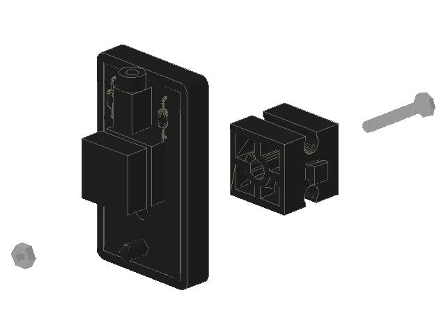
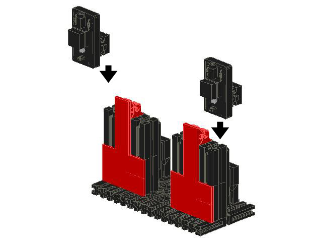
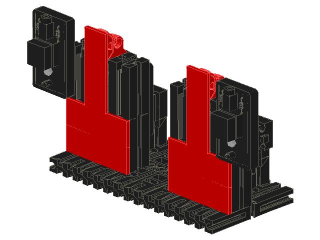
Fix two Touch Sensors onto Building Block 15s with Counterbore with nuts and bolts. Fix one switch onto the end block stack on each end of the model.
Connect LED Guess-O-Matic to the BRAIN

Use the Sensor Cables to connect the two LEDs to ports 6 and 7. Connect the Touch Sensors to ports 0 and 1.
Program the Game
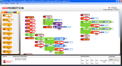
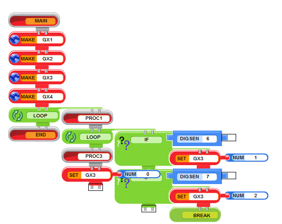
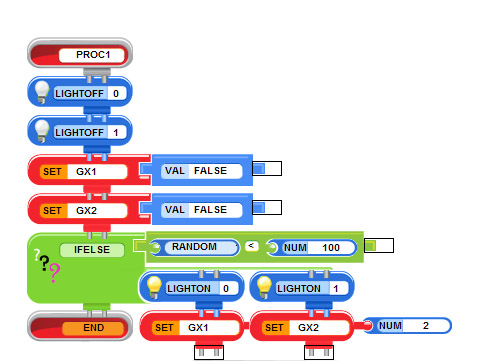
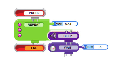
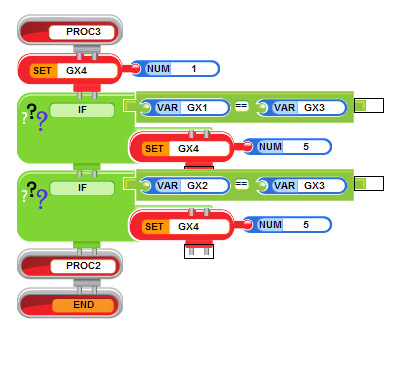
I used the PCS Visual Logo in the CORTEX PROGRAMMING environment.
I took screen captures so that the program can be replicated.
I took screen captures so that the program can be replicated.
Play the Game!
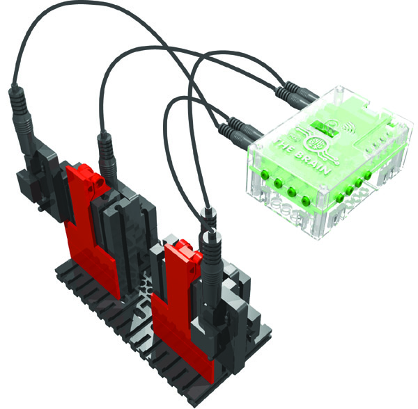
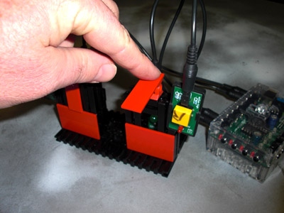
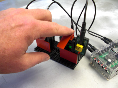
Once the BRAIN has power and the program is downloaded, play GUESS-O-MATIC.
Run the program on the BRAIN by hitting the Start/Run button. Select the LED that is lit and hit the appropriate Touch Sensor. If your guess is correct, you will hear a happy tune. If it is incorrect, you will hear a single beep.
Watch a video of the LED GUESS-O-MATIC:
Run the program on the BRAIN by hitting the Start/Run button. Select the LED that is lit and hit the appropriate Touch Sensor. If your guess is correct, you will hear a happy tune. If it is incorrect, you will hear a single beep.
Watch a video of the LED GUESS-O-MATIC: