Arduino LED Matrix
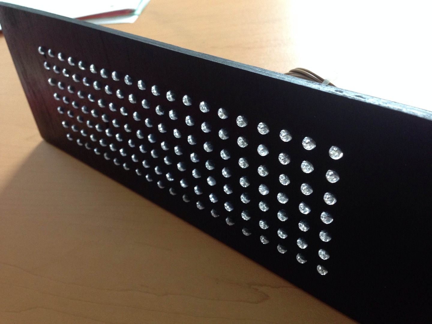
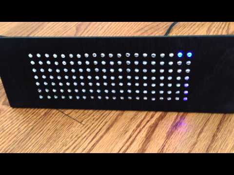
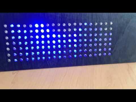
In this short tutorial you will learn how to make an Arduino-powered LED matrix. Unlike several other designs, this one uses a "companion" computer to notify the Arduino which LEDs should be powered.
I have provided the code for the Arduino, as well as some Java code for displaying text on the LED matrix (this includes a custom-made 7x5 character font).
Things to keep in mind:
- With the software provided, a maximum of 7 rows is possible if you want to display text. It would technically be possible to increase this limit to 15, but I'll leave that to someone else.
- If you want to just display sound values (i. e you want to light up the LEDs consecutively from the bottom), it would be technically be possible to use up to 127 rows.
- I cannot release the code for the audio visualization(sorry!) for various reasons
The Materials

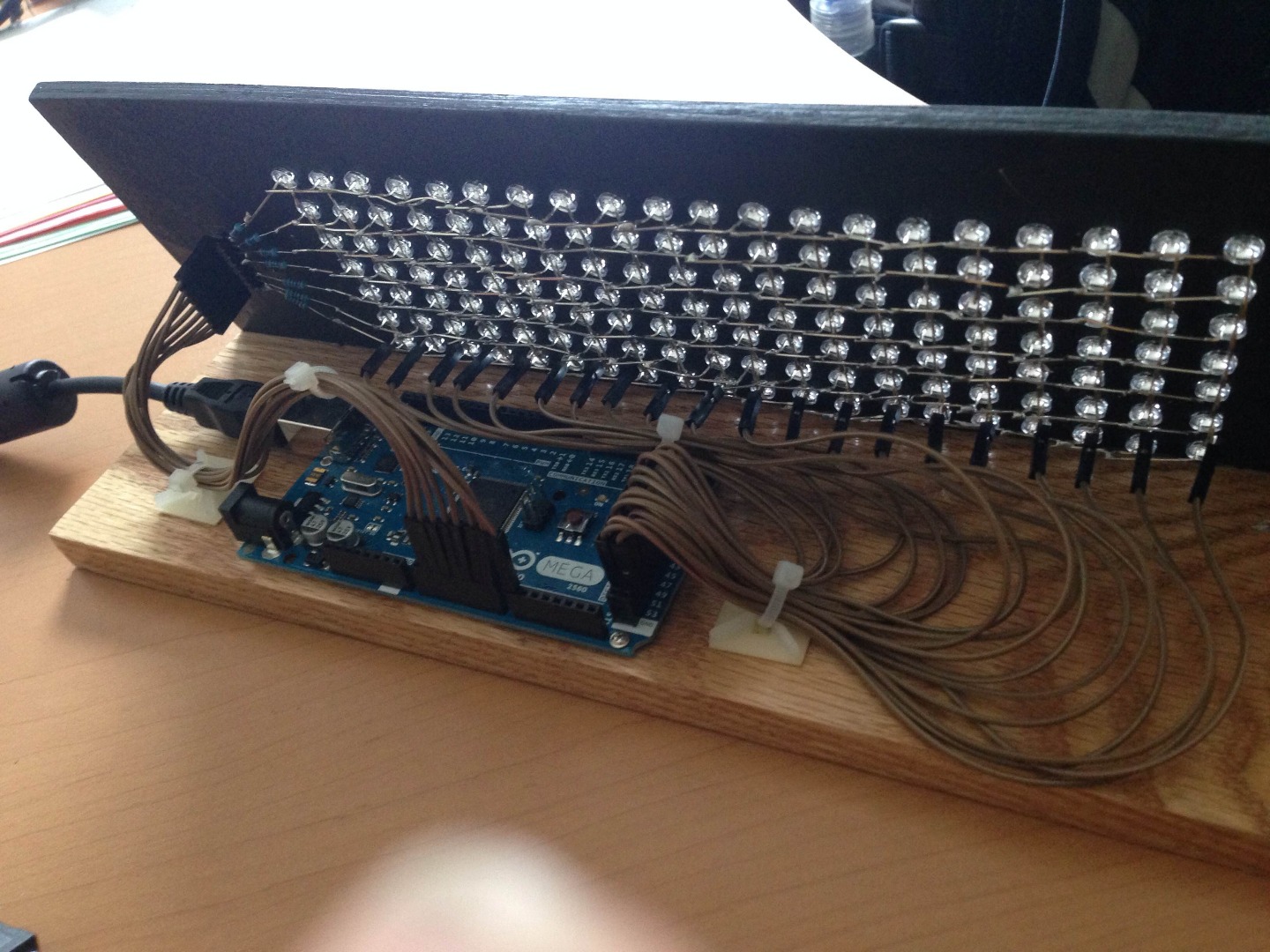
For this project, you will need the following materials:
- An Arduino that has as many digital pins as you want rows and columns combined. (eg, If you want to have a 7x5 LED matrix, you need at least 12 digital pins on your arduino). I used an Arduino Mega 2560 as the Mega has 54 digital I/O pins and was the only which allowed me to make a 20 by 7 grid (I needed 27 pins).
- In order to connect your Arduino to the LED matrix, it would be helpful to have female to male breadboard wires
- Enough LED's for your matrix. (With a 7x5 matrix, you need 35 LEDs). For this project, I used the blue LEDs which can be found here
- The link above also has the resistors you need. You will need as many resistors as you have rows in your LED matrix
- A wooden board for mounting the LEDs. You'll need some reasonably thin wood for this project. How thick and how big the wood should be depends on how much you want your LEDs to protrude out the front and how far apart you want the LEDs to be spaced. I would recommend a 1 cm spacing between your LEDs(mine were 5mm in diameter). Remember to leave some space on all sides(especially to the left and right of the matrix).
- A companion computer to connect the Arduino to.
- Spray paint for the added effect.
You will also need various tools: drill (+ a selection of drill bits), pliers, clippers(or wire cutters), and a soldering iron(with solder)
Cutting/Drilling the Board
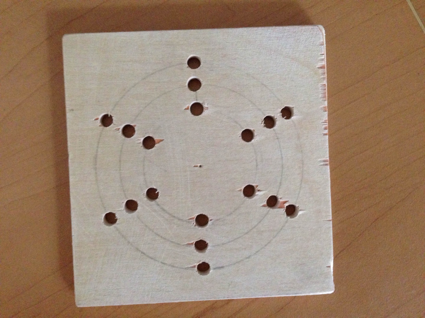
(The picture above is of a prototype board, not the final product. Use it as inspiration to come up with other cool LED patterns)
The first thing you need to construct is the board on which the LEDs will be mounted. Here you have several options on how to structure the LED board. You could design you LED board in the classical, grid LED matrix or you could take a more interesting approach by making a circular LED pattern.
In this step you will also have to take into account the spacing of your LEDs. I would recommend having the centers of the LEDs be 1 cm apart from each so that the LEDs(which are 5mm in diameter) will be tightly packed(but not so tightly it is impossible to work with).
The size drill bit you should use depends on the size of the LEDs. I bought a special 5mm drill bit so the LEDs would fit exactly. Take into consideration that if you are going to spray paint the board, this will make the holes slightly smaller.
Spray Painting the Board
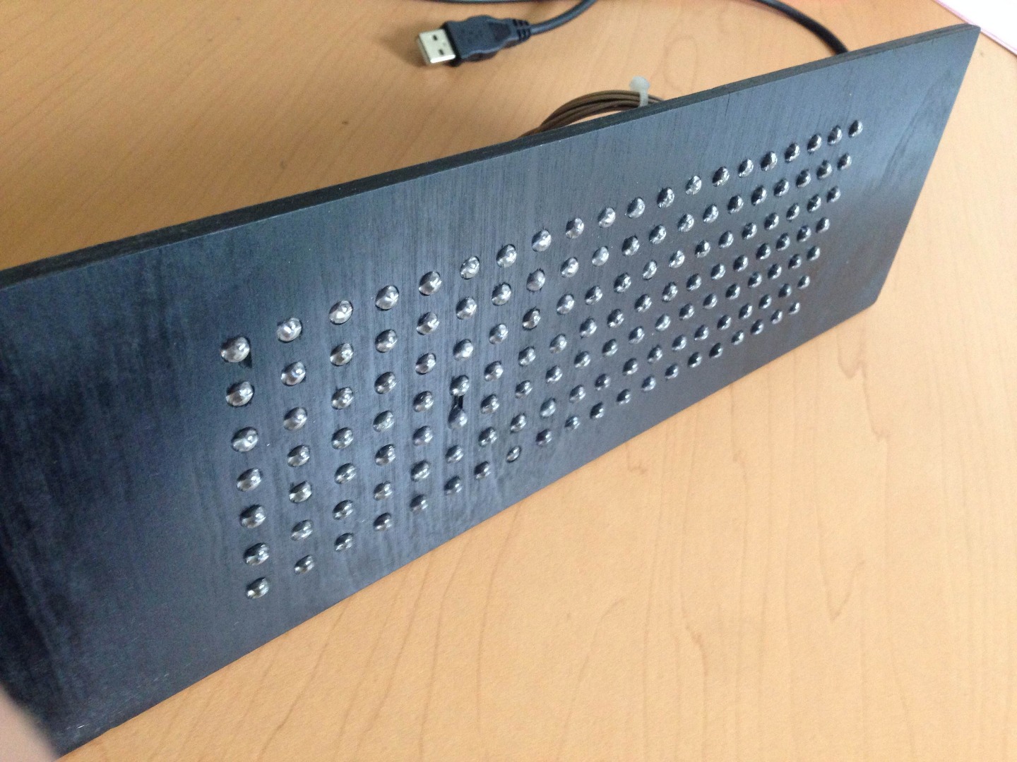
If you want to make your board a certain color, then now is the time to do that. Before inserting your LEDs, you should consider spray painting your board (as this will not be an option once the LEDs are in place--you don't want to spray paint the LEDs).
I chose black as the preferred color for my board as I happened to have a black spray paint on hand and thought it would go well with my blue LEDs.
Soldering the LED's

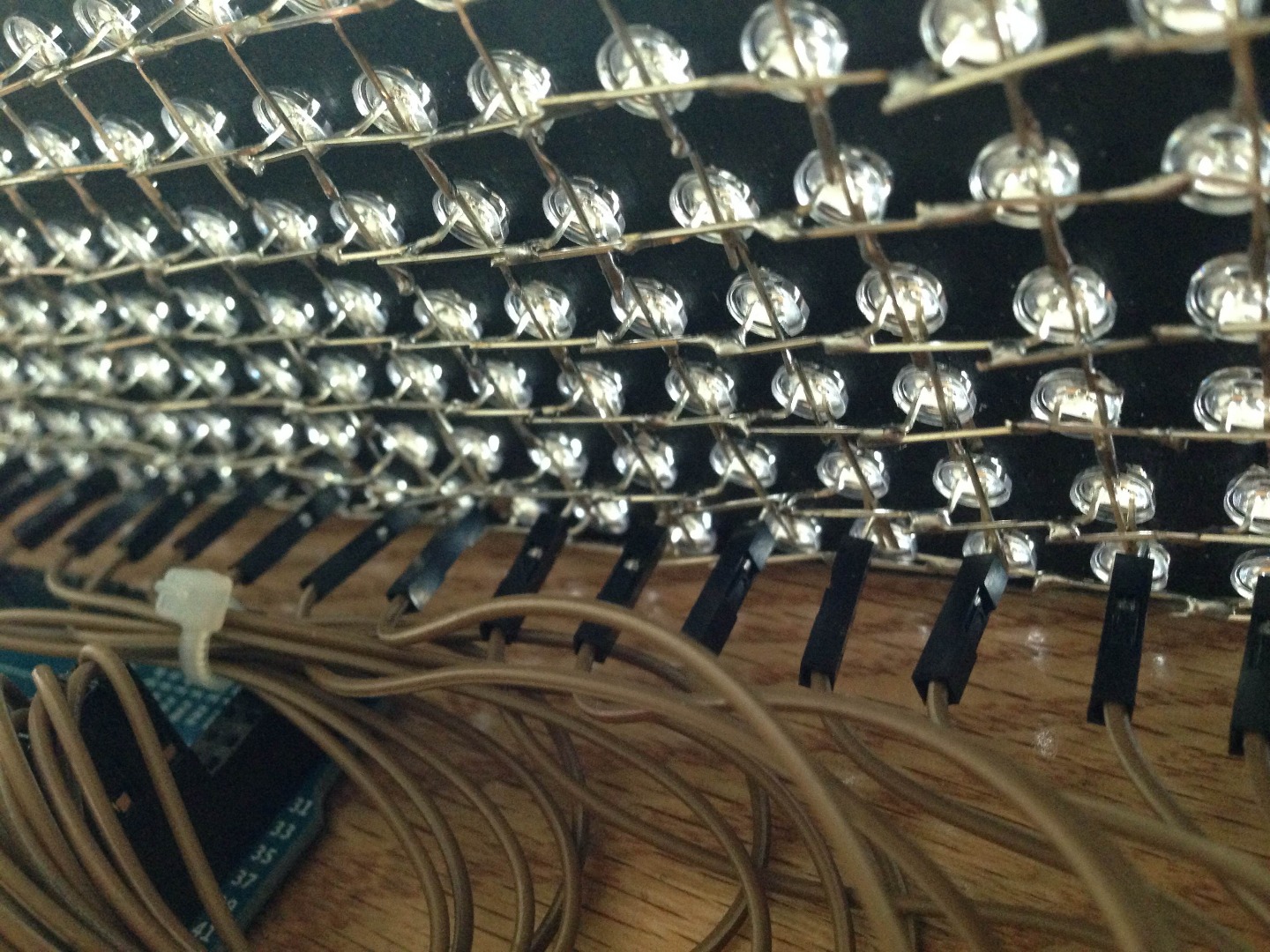
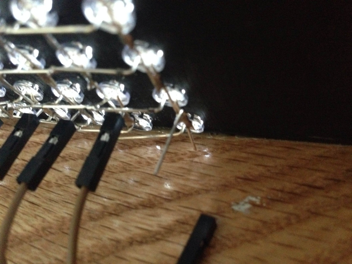
The next step is soldering the LED's. I have provided a schematic on how the LEDs should be wired up (the rows should never cross with the columns. I was unable to change this after exporting the diagram).
Note: In these instructions, I generally refer to the legs of the LEDs as "pins" for the lack of more specific terminology.
If found the best way to solder them was column by column. I have broken down the process into several steps.
- Insert the LEDs into the column. Assure that all the LEDs are in the same positive/negative orientation. Positive should be on the left, while negative should be on the right.
- Take the column pins (right "leg" of the LEDs) and bend all but the bottom pin down (towards the ground) so that they are flat with the board.
- For the lowest pin, bend the pin down, but in the opposite direction of the other column pins(bend it upwards, away from the ground).
- Then, bend the lowest pin up about halfway between the bottommost pins. This will allow you to easily plug the column pins to the Arduino.
- Next, use pliers to hold the base of the row pins so you can bend the row pins down horizontally. Do not bend them down all the way (so that the row pins do not touch the column pins)
- Use some clippers(or wire cutters) to neatly trip the legs of the LEDs so that they do not protrude too far down or to the left.
- Solder the row pins to the previous column's row pins. Then solder column pins to the next lowest LED's column pin. Assure that no row pins and column pins ever touch.
Downloads
Connecting the LEDs to the Arduino
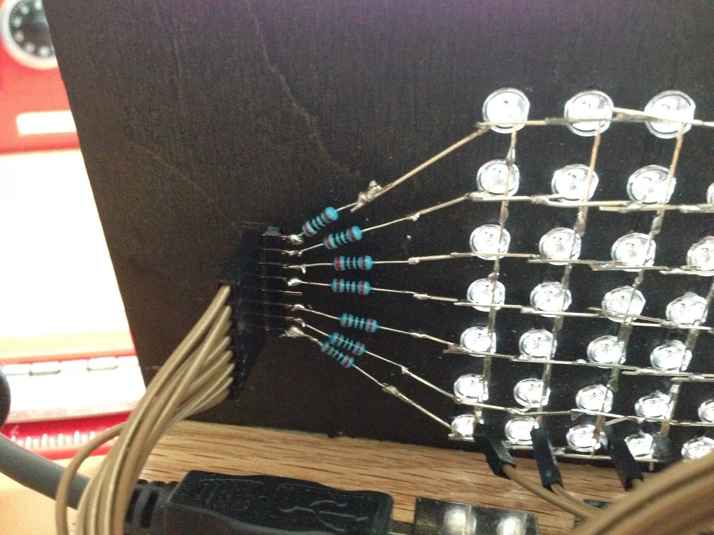
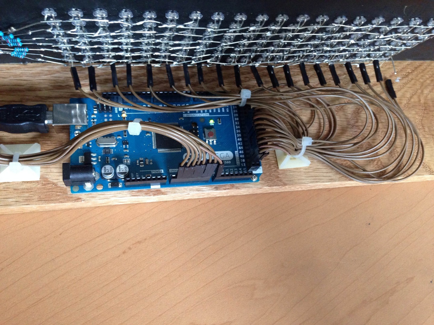
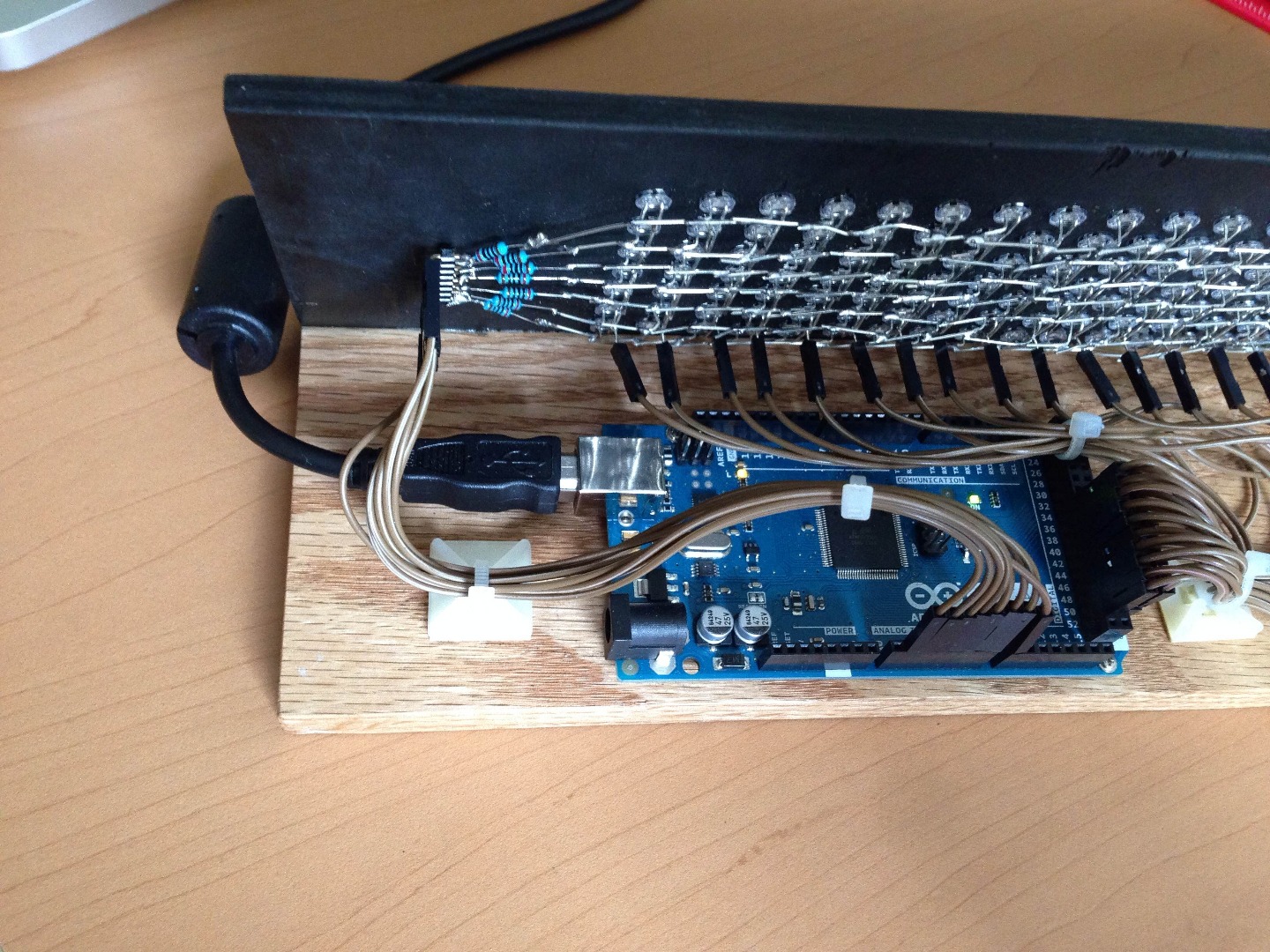
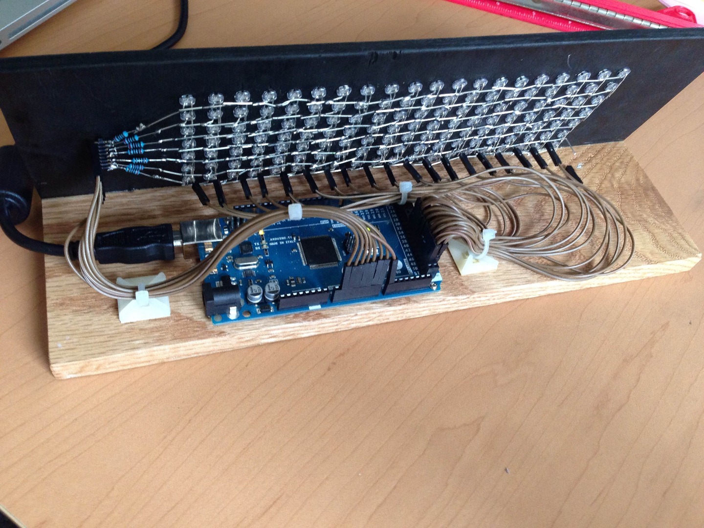
The first step will be to solder the row resistors on to the row pins of the leftmost LEDs, as shown in the image. I used a connector I had lying around to neatly organized the pins. If you do not happen to have such a connector, you can bend up the left leg of the resistors in a similar fashion to the lowest column pins.
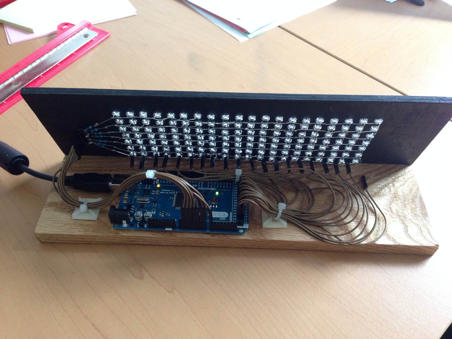
Then, use the breadboard female to male cables to connect the rows to the Arduino. The male side should be connected to the pins sticking horizontally out of the LED board. Which pins you use on the arduino don't matter. Both analog and digital should work, but know which pins are plugged in where.
At this point, if you are so inclined, you can attach a base to the bottom of the LED board using wood glue or any other adhesive of your choosing.
The Code
Excellent! With the physical assembly of the board done, it's time to get coding. I have written some Arduino code for receiving and displaying the LED values sent from the computer to the Arduino (the technique used to light multiple LEDs at the same time is called multiplexing, give it a google if you have some time). The arduino code is in the
I have also written some Java code, also attached, for writing simple programs to display text on the Arduino. The example java program will display the current time in a news-ticker manner. For instructions on how to run the java code check the README.txt in the zip file attached.
You will need to adjust the arduino code to use the correct number of rows, columns, and input pins. Do this by changing the #define ROWS and #define COLUMNS lines to the number of rows and columns you are using. Change the rowPins and columnPins to the input pins you are using.
For the more advanced coders, I will give a brief description on how the Arduido "API" works.
Every byte the Arduino receives is one band(i.e. column). The bands to the left are shifted one over. If you want to overwrite the entire LED matrix at a time, just keep writing column values until you have overwritten the entire LED matrix.
There are two ways of specifying column values:
The first is the specify the number of LEDs (from the bottom) to light up. (eg. writing a 1(0x01) will make the bottom most LED light up. Writing a 2(0x02) will make the bottom 2 LEDs light up. Writing 3 will.... And so on and so forth.
The second mode is where the left most bit is one(add 128 to the value). This signifies to the Arduino code to interpret the values differently. In this mode, each bit represents a different light, with the rightmost bit signifying whether the bottom LED is on or off. For example, the byte 0b10000101 would light up the first and third LEDs from the bottom.
The software provided(including the font) is yours to distribute and modify, commercially or non-commercially.