Using a LDR and Arduino to Control a LED
by IMadeThisAccountForAClass in Circuits > Arduino
1413 Views, 1 Favorites, 0 Comments
Using a LDR and Arduino to Control a LED

This circuit and code will allow you to turn on an LED using a Light Dependent Resistor.
Supplies
Arduino Uno (1)
Breadboard (1)
Light Dependent Resistor (1)
LED (1)
10k resistor (1)
breadboard wires (6)
Build the Circuit

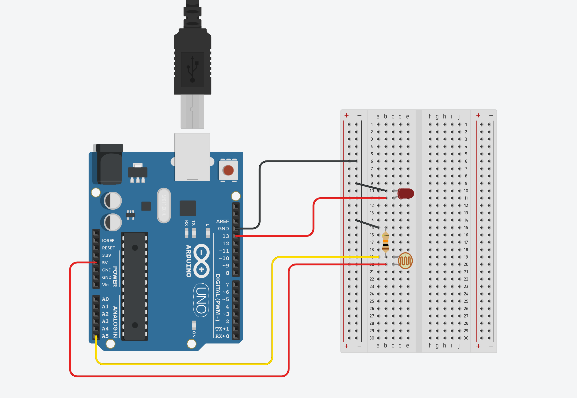
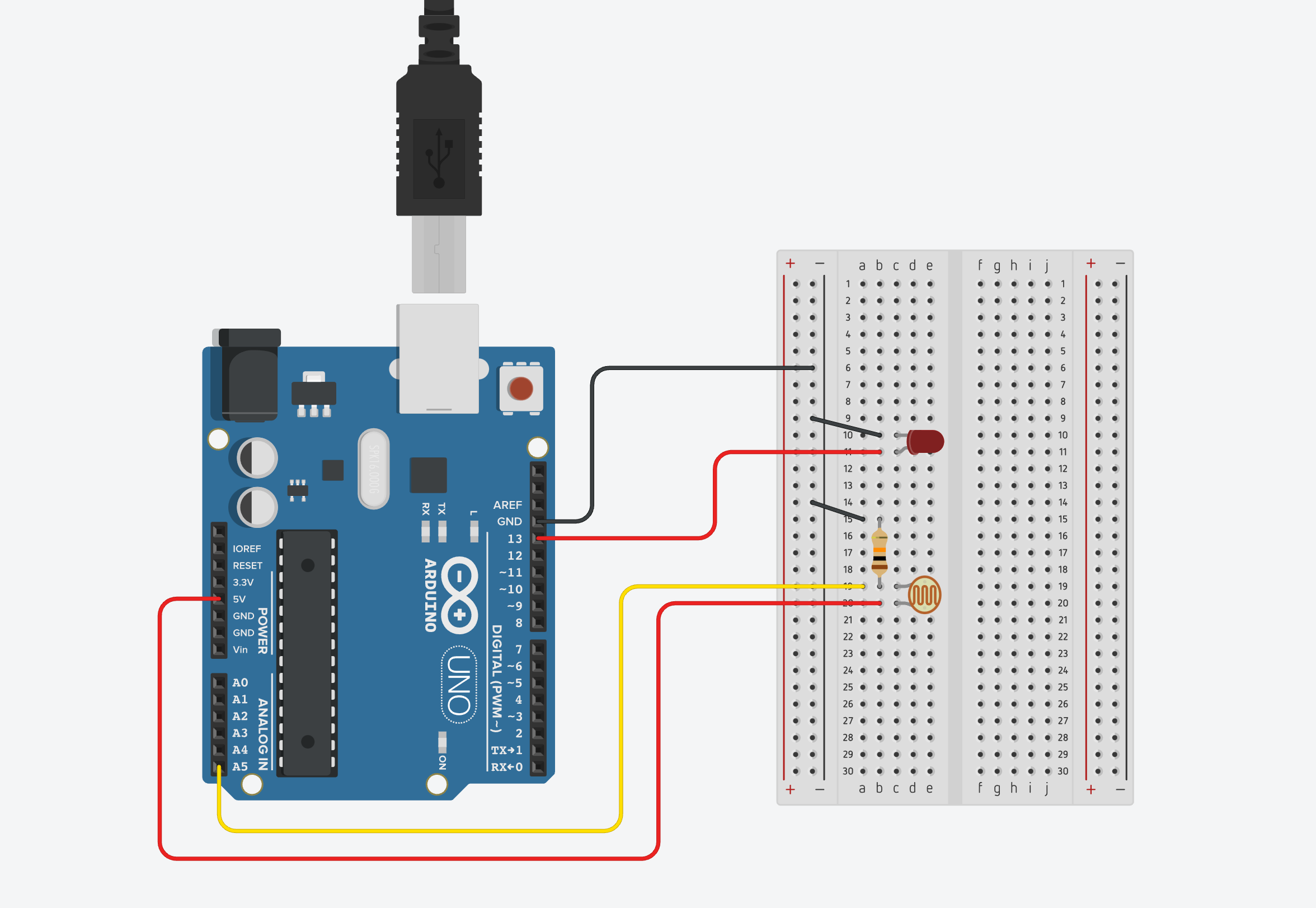
Follow this simple diagram.
Copy This Code
int photocell = A5;
int photocellReading = 0;
int led = 13;
int brightness;
void setup() {
pinMode(led, OUTPUT);
Serial.begin(9600);
Serial.println("The Serial monitor connected");
}
void loop() {
brightness = map(photocellReading, 830, 621, 0, 255);
photocellReading = analogRead(photocell);
analogWrite(led, brightness);
Serial.print("The analog reading of LDR is ");
Serial.println(photocellReading);
delay(100);
if (photocellReading <= 775)
{
digitalWrite(led, HIGH);
}
Modify the Code to Your Environment
Because the lighting in every room will be different, the code needs to be modified to use the LDR reading values taken at your location. To do this open the Serial Monitor in the Arduino app (Tools -> Serial Monitor), and take note of the highest number read when the sensor is uncovered, then place your hand over the LDR and record that number. These numbers will fluctuate but try to find an average for each. Once you have these two numbers put them in place of the numbers 830 and 621 (the readings taken from my workspace) in line 13 of the code, high and low respectively.
Now subtract around 50 from your highest reading and put that number into line 19 in place of 775. This number will be the threshold for the LDR to turn on the LED.