LATTEintosh Cooling System
by Arnov Sharma in Circuits > Computers
2399 Views, 14 Favorites, 0 Comments
LATTEintosh Cooling System

.gif)
.gif)

Hey everyone and welcome back.
So several weeks ago, I created the "LATTEintosh PC," a Mini PC inspired by the Macintosh 128K that uses the Latte Panda 3 Delta SBC as its brain and features a perfect IPS display in addition to a whole body 3D printed from PLA.
It runs Windows 10 and can serve as a daily driving computer if you only require a device for online browsing and casual gaming.
Everything was excellent, but when playing some games, like CSGO, the onboard Mobile Intel Processor gets too hot and its CPU usage is over 90%, which means a lot of heat is being generated. Fortunately, the Latte panda has a very nicely constructed and implemented heatsink with a fan that is extremely silent.
It effectively cools the Latte Panda, but because the PC body provides limited ventilation for the Latte Panda, an external fan was a necessary accessory. This component will direct air into the PC from the back side, and the Latte Panda's fan will then take over.
I did add the fan, but there was a problem because the entire PC was supplied by a 5V source while the fan I was using had an operational voltage of 12V. It's also not a good idea to add a fan to Latte Panda's power source because it could cause voltage spikes that could harm the SBC.
So I came up with a clever solution that uses lithium batteries combined with a PCB to create a battery pack that will supply 12V to run the fan.
Supplies
.gif)
Following are the materials used in this built-
- Li-ion 11.1V 3S BMS
- DC Jack
- Custom PCB (which were provided by PCBWAY)
- Li-ion Cell 18650 Holder
- Li-ion Cell 18650 3.7V 2600mAh
- Diode M7 SMA
- Resistor 0603 10K
- 3mm LED
- 3D Printed Circuit Holder
- Screws
- Rocker Switch SPST
- JST connector
- JST Wire Harness
BMS
.gif)


A key component of this project is the BMS, or battery management system.
The charge and discharge cycles of Li-ion cells connected in series are managed by a circuit known as a BMS. It offers characteristics like over-charge and over-discharge protection, and high and low cutoffs, which prevent cell chargers from going over a particular voltage or allow cell dischargers to go over a specific voltage.
BMS is available in several configurations, including 2S, 3S, 4S, and 6S. The 3S BMS we are using provides an output voltage of 11.1 volts. Here, S stands for series.
I'm using a 3S 12V generic BMS that is widely available online.
PCB Design


The project's design was really straightforward; after adding the BMS, we connected each Li-ion Cell Holder in series to the BMS in accordance with the wiring schematic.
I attached two JST connectors to the BMS's VCC and GND; the DC Fan and Rocker Switch will plug into these two JST ports.
Additionally, a DC jack has been added, along with a diode between the VCC and charger IN and an LED with a resistor placed before the diode, which will light up when the charger is plugged in.
PCBWAY

.gif)

After placing everything and finalizing the board, I send its Gerber data to PCBWAY for samples.
I used PCBWAY PCB Service for this project. I uploaded the Gerber file for this project on PCBWAY's quote page. For this Battery Pack board, I went with a red solder mask and white silkscreen.
After placing the order, I received the PCBs within a week, and the PCB quality was pretty great. The silkscreen was perfect, and they did an awesome job of making this PCB with no errors whatsoever.
You guys can check out PCBWAY If you want Great PCB Service at an Affordable rate and low price.
Board Assembly
.gif)
.gif)
.gif)
.gif)
.gif)
.gif)
.gif)
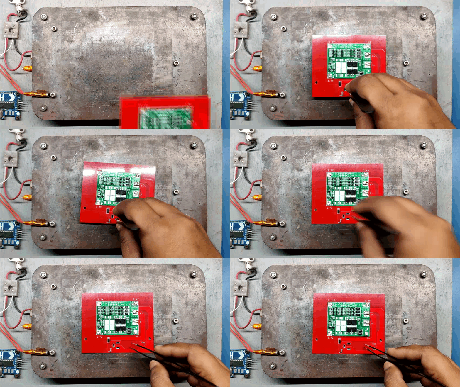
- Board Assembly Process begins by first adding solder paste to each component pad one by one.
- Next, using a tweezer, we pick and position each SMD component in its designated location which is the BMS, Diode, and Resistor.
- Following that, we carefully lifted the entire circuit board and set it down on the SMT Hotplate, which heats the PCB from below up to the solder paste melting temperature. As soon as the PCB reaches that temperature, the solder paste melts, and all the components are connected to their pads.
- The Li-ion Cell Holder is then added to the PCB's bottom side by first soldering one side of the pad and then attaching the Cell Holder to its position.
- Then, we replace them with a DC jack and two JST connectors, soldering their pads from the top side of the PCB.
- Finally, we attach a 3mm indicator LED to the PCB's LED pads using two wires.
- The circuit is now assembled.
Li-ion Cells Details
.gif)

.gif)
Because the BMS we're using is a 3 S BMS, we can connect at least three cells in series, boosting each cell's voltage from 3.7 to 11.1 volts while maintaining the cells' capacity.
We start by measuring the voltage of each cell. Although the voltages of these cells vary, don't worry; the BMS will charge the cells up to their maximum voltage threshold and properly balance them. implying that even if each cell's initial voltage is different, following the first charge, they will become balanced throughout charging.
We place the cells in the appropriate polarity into the cell holders after confirming their voltage.
Testing
.gif)
.gif)
.gif)
.gif)
- First, check the battery pack voltage, which should be 11.1V after placing the lithium cells in the cell holder.
- Then, using a JST wire harness, we connect a 12V DC fan and a rocker switch to the main circuit.
- The fan will turn on when we turn on the rocker switch, indicating that the system is functioning.
- Finally, we connect a 12V 1A power source to this PCB's DC connection to charge the battery pack; when we do so, an indication LED will glow.
We may now proceed to the next phase, which is to examine the circuit holder and assemble it with the PCB battery pack since everything in the PCB Battery Pack is functional.
3D Printed Circuit Holder

.gif)

The circuit holder for the LATTEintosh Project is shown above, which I modeled in Fusion 360.
I had to alter the current Lid portion and vertically add the circuit before exporting the mesh file and printing the part on my Ender 3 with transparent PLA by using a 0.4mm Nozzle with 0.2mm layer height.
Circuit Holder Assembly
.gif)
.gif)
.gif)
.gif)
.gif)
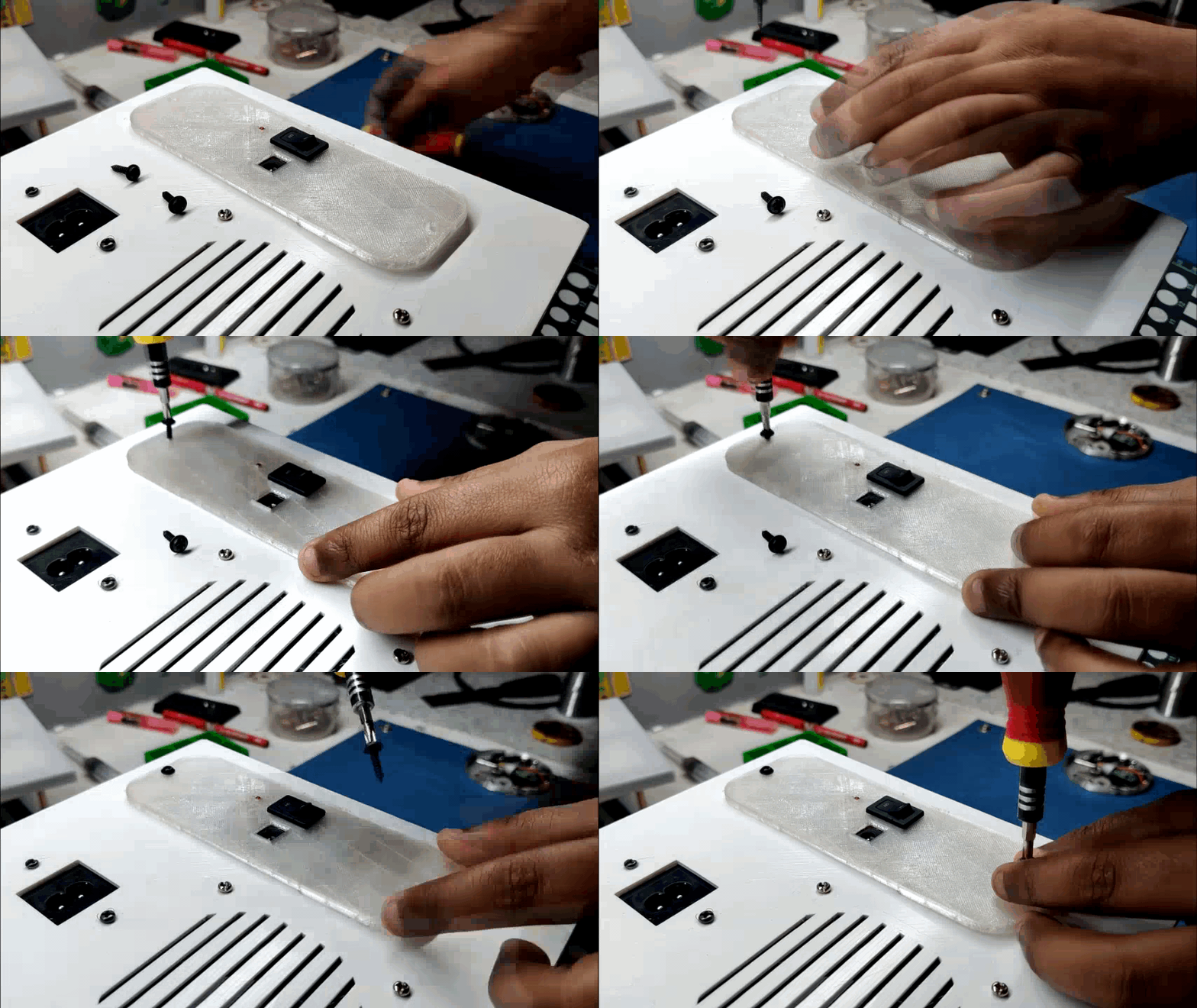
- Adding the PCB Battery Pack into the Circuit Holder Part serves as the first step in the circuit holder construction. The PCB is simply slid into the holder.
- The 3mm LED is then inserted into the LED Hole on the circuit holder's body.
- Now we insert the rocker switch into the circuit holder and connect the rocker switch's JST wire harness to the JST connector provided on the PCB Battery Pack.
- Finally, two M2 screws are added to secure the circuit to the circuit holder part.
The assembly of the circuit holder is now finished.
Adding Circuit Holder Assembly to LATTEintosh
.gif)
.gif)
- Next, we add the JST wire harness of the DC fan to the JST connector on the main circuit.
- Finally, the assembly part is finished by fastening the circuit holder assembly to the lid with two M2 screws.
RESULT

.gif)


- The end result of this entire build is that the fan has a separate power source that is located inside the PC case and is powered by onboard lithium cells that are connected seperately from the LattePanda Power supply.
- There is nothing particularly special about this; the fan can only be turned ON or OFF using the rocker switch. It is simple and effective.
CPU Temperature


We begin this test by starting the Core Temp software to track the temperature of the CPU cores. The fan is ON, the temperature is 41°C, and the CPU usage is under 12%.
The temperature reaches 63°C after 20 minutes of playing Minecraft Java Edition, and the fan was ON the entire time.
After 20 minutes of playing the same version of Minecraft with the fan switched OFF, the CPU reached a temperature of 77°C.
13°C isn't much of a difference, but turning ON the fan and moving air inside can assist to increase the airflow.
For much better results, I need to design a fan nozzle that will direct air directly onto Lattepanda; at the moment, the air is simply blowing inside the case because there is no air guide.
The final conclusion is that the battery pack functions as intended and can power the fan for a continuous period of more than 6 hours, which is sufficient. A 12V 1A charger can fully recharge the battery pack in 2.6 hours.
This is it for today folks. I hope this article was useful, if yes, then leave a comment.
Special thanks to PCBWAY for supporting this project; do check them out for great PCB service at a lower cost.
Thanks again, and I will be back with a new project soon.