Kubic - a Printable ITX PC Case With a Handle
by WhoIsLudwig in Workshop > 3D Printing
9338 Views, 71 Favorites, 0 Comments
Kubic - a Printable ITX PC Case With a Handle


Kubic is an ITX PC case designed to be printed on smaller 3D printers, such as a Prusa Mini or a Bambu A1 Mini. The larger parts take 170 x 170 mm, which means they fit nicely on 180 x 180 mm beds.
It takes design cues from the classic computers, such as NEXT machines, or older Power Mac G4 Cube from the early 2000's. The handle also reminds a bit of the venerable Nintendo GameCube, while ensuring that the upper heat exhaust remains clear. "Classic vibe" is definitely a defining word here.
The case can house a full ITX PC build, including a discreet GPU up to double slot and 220 mm long. You won't fit larger cards in there, but it's enough for quite a few cards available on the market today. Cooling is ensured by a 140 mm chassis fan (up to 30 mm thick) mounted on top. It takes fresh air from under the case (hence the feet) and it exhausts the heat through the top. My tests resulted in good cooling performance despite the single fan, stabilizing the CPU temp at 94° C and GPU at 75° C in an absolute worst case scenario (both CPU and GPU maxed out for two hours). Ingame, I never went north of 75°C for both CPU and GPU. The case also has enough space to fit a pretty massive CPU cooler, which could even improve thermal performance over my own tests.
Supplies


For this build you'll need the following tools and supplies :
Supplies :
- M3 Cylinder head hex screws :
- 8mm long (48)
- 5mm long (optional : 2 screws per 2.5" drive that you wish to install)
- M4 Cylinder head hex screws :
- 15 to 20 mm long (16)
- M5 Cylinder head hex screws :
- 30 to 35 mm long (8)
- 20 mm long (2)
- 4 M3 standoffs (6mm high)
- Brass inserts :
- M3 (48)
- M4 (17)
- M5 (10)
- Two 12mm round momentary switches. You'll have to build the switches yourself, so you'll probably need at least a crimping tool and some Dupont connectors. Please refer to your motherboard manual for the switches and LEDs pinout.
- (Optional) 2xUSB 3 panel mountable expansion for motherboard header such as this one : https://www.amazon.fr/dp/B00L2NWA1Q/ref=pe_27091421_487052621_TE_item?th=1
Tools :
- 2.5mm, 3mm and 4mm hexagonal screw driver
- P00 Phillips Screwdriver
- 5mm hex pipe driver
- Soldering iron
- 14mm hex key
For the computer parts, here's the requirements :
- ITX motherboard. The case is large enough to hold up to 100 mm height CPU heatblock and fan.
- If you wish to use a discreet GPU, make sure that the card and the cooling system fits. You can fit any card up to 210 mm long and 2 slots thick (up to 41mm)
- SFX power supply. There is only limited space inside the case, so I made the choice to use a smaller PSU. However, it ** may** be possible to modify the case to allow for a bigger ATX PSU. But it would be at the expense of the inner airflow and available room for the CPU heatsink.
- 140 mm chassis fan, up to 30 mm thick. Depending on your system, this one may be optional (if you're only using an APU, or for lighter duty work, for example), but I would STRONGLY recommend to use one, since it allows to keep a constant flow of fresh air inside the case.
- Optionally, you can install up to four 2.5 inch drives in which case, you'll need the corresponding SATA cables.
For reference, here's the config I used :
- Motherboard : AsRock B550M-ITX/ac
- CPU : AMD Ryzen 5 3600
- GPU : Sapphire PULSE Radeon RX 6600 8GB
- SSD : Corsair MP600 PRO XT 1To M.2
- Additional drive : King Spec 1Tb SSD drive
- RAM : Corsair Vengeance LPX 32 Gb (2x 16Gg kit)
- PSU : Be Quiet! SFX Power 3 450 Watts
- CPU cooler : AMD Wraith Spire
- Chassis fan : Arctic P14 PWM PST
Of course, you'll need a 3D printer with a printing surface of at least 180 x 180 mm and about 1.5 Kg of filament, including purges, brims and supports. Once the supports removed, there is about 1.3 Kg of material left.
I made all of my prints fully in PLA with great results and no trouble at all, even thermal wise. I used the case for all my stress tests and playing sessions for two months now and never had an issue with the print itself, even in full load with the case completely closed. PETG can also be a good option, too.
For reference, here's the filament I used on my build to get that nice "NES" themed look :
- Amazon PLA light grey for the upper parts
- Amazon PLA dark grey for the lower parts
- Overture Wine Red PLA Pro for the markings
- Elegoo black PLA for the front panel.
Everything has been printed on my Bambu A1 Mini printer with the stock textured plate and an additional smooth plate and the AMS Lite addon for the multicolor front panel.
TLDR - If You Don't Wanna Bother Reading the Whole Instructions


Here's summed up instructions for quick mounting. The whole build should take less than 1 hour once everything is printed. Skip to the next part for much detailed instructions
- Heat press all of the inserts into the corresponding holes.
- If you use the front USB ports, screw the extension from behind, the screw head should be inside the bracket hole.
- Mount the right side by inserting the corners in their housing for the frame structure, then use 8 M4 screws to hold the pieces together. If necessary, refer to the STL filenames, or mark every part in order to tell each part apart
- Use a 5 mm hexagonal pipe key to install the motherboard standoffs in the smaller holes by threading directly through the plastic. Screw until you feel a resistance but don’t over tighten in order to avoid stripping the plastic around. Make sure the standoff is straight and flush against the surface.
- Install the Motherboard on the four standoffs, with the CPU, the cooler and the RAM also installed. I you have a PCIe GPU, install it now. If you have the front USB, you can also connect it to the motherboard now.
- Using four M5 x 30 to 35 mm long screws, install the « horizontal » frame bars, starting by the rear bottom one, which will keep the GPU from wiggling. You can also attach the GPU to the bottom of the frame using a M4 screw. (However, this part is not strictly necessary since the case will hold the card pretty well in place)
- Build the left side of the frame in the same way you built the right side. If necessary, refer to the models in your slicer. Alternatively, you can mark every part in order to tell them apart.
- Install the right side on top of the rest of the structure and use the 4 remaining long M5 screws to hold it in place. The frame is now complete.
- Put the case upside down (feet facing up) and install the lower panel by using 8 M3 screws.
- Put the case up on its feet.
- Take your 140mm chassis fan and install it in the dedicated recess of the top panel. Then, plug the fan to the Motherboard and install the panel on the top side of the case using 8 M3 screws.
- Use the two handlers and the 2 shorter M5 screws to install the handle. The screws must go through the handlers and the dedicated holes of the top panel. They must be tightly screwed in order to prevent the handle to get loose.
- Now leaving the PSU out of the case, plug every power cable you need from the PSU and leave the rest hanging. If you plan to use the SATA drives, route the SATA power cable over the front of the motherboard and leave it hanging there for now.
- install the PSU in its slot against the left side of the frame and screw it in place. If your PSU is non modular, tuck every unused cable out of the way. Make sure they won’t make contact against the CPU or the chassis fan. You can use zip ties in order to keep everything tidy.
- Now install the back panel. if your motherboard has a separated I/O back plate, insert it into the housing, then place the panel on the back of the case and use 8 M3 screws to hold the corners.
- You can install up to 4 SATA drives on the right panel. Place the drive in one of the two slots, inserting the corresponding « bumps » into the side screw holes, then attach the outer side of the drive with 2 screws through the holes on the slot. Repeat the operation for every drive you wanna install, then plug the power and the SATA cable. Route the SATA ribbons over the front and connect to the motherboard. Then install the panel with 8 M3 screws.
- Install your POWER and RESET buttons on the front panel and make the necessary connections to the motherboard. You may have to build your own switches, whether by crimping or soldering Dupont connectors to it. Refer to your board manual to get the exact pinout.
- Close the front panel and screw it down with 8 M3 screws. Be careful not to pinch the switches wires in the process.
- Now close the case by installing the left panel. Make sure no wire risks getting into a fan, that everything is tightly packed inside and that there is a sufficient air flow to ensure an effective cooling.
Congratulations ! Your Kubic case is now ready to be turned on. Enjoy !
Printing


Please see my Printables page for detailed printing instructions. You can also refer to the joined pictures.
I'm providing a ".3mf" file for reference (Created with Bambu Studio, not exactly sure it will open correctly with other slicers, but it's still worth a try). If you can use it directly, that's great, you should have excellent results. Otherwise, you can refer to the pictures for placement and plate composition.
Downloads
Preparing the Parts


Once all the parts are printed, we have to install all the brass inserts. I usually use my soldering iron with a round tip with pretty good results.
Score the contour of the holes with a screwdriver. It will remove any printing defects, and make the entry of the hole slightly larger, which will ultimately help stabilizing the insert before insertion.
Hold the insert straight with pliers, then with your soldering iron set to 275°C, gently push the insert down the hole. Be sure to push straight downward. As soon as the insert is flush with the surrounding surface, remove the iron and let cool for a few seconds. Just be gentle and take your time
Each lateral frame bar uses 4 M3 inserts and 2 M4. Horizontal bars use 4 M3 and 2 M5. Don't forget the 2 M5 inserts into the handle and the M4 into the GPU housing of the lower back bar. However, this one is optional and can be ignored.
Tip : You can use some vise to ensure the stability of the part you're working on. I'm using this 3D printed one myself, that proved very convenient : https://www.printables.com/model/51074-fast-operation-vise
Adding the Standoffs


Use a 5 mm hexagonal pipe key to install the motherboard standoffs in the smaller holes by threading directly through the plastic. Be careful to thread straight down the hole. Screw until you feel a resistance but don’t over tighten in order to avoid stripping the plastic around.
Make sure the standoff is straight and flush against the surface. You can make a couple of tries if necessary, but not too much, or the plastic will begin to wear off and the standoff might become loose. Once again, take your time and it should not be much of a problem
Installing the Front USB Extension


If you use the front USB ports, install the extension on the bracket of the front right stem. Screw the extension from behind, the screw head should be inside the bracket hole.
Assembling the Right Frame


Now we can begin the case itself.
First, mount the right side by inserting the corners in their housing on each side of the right frame bars. Then use 8 M4 screws to hold the pieces together. The frame should be quite rigid in the end.
Be careful to use the right part at the right place but don’t worry : if you make any mistake, you can always go back and correct it. If necessary, refer to the STL filenames, or mark every part in order to tell them apart.
The Computer


Install the Motherboard on the four standoffs, with the CPU, the cooler and the RAM already installed. If you have a PCIe GPU, install it now and leave it hanging for the moment. Also leave the USB extender hanging, we'll plug it in later.
Adding the Horizontal Structure


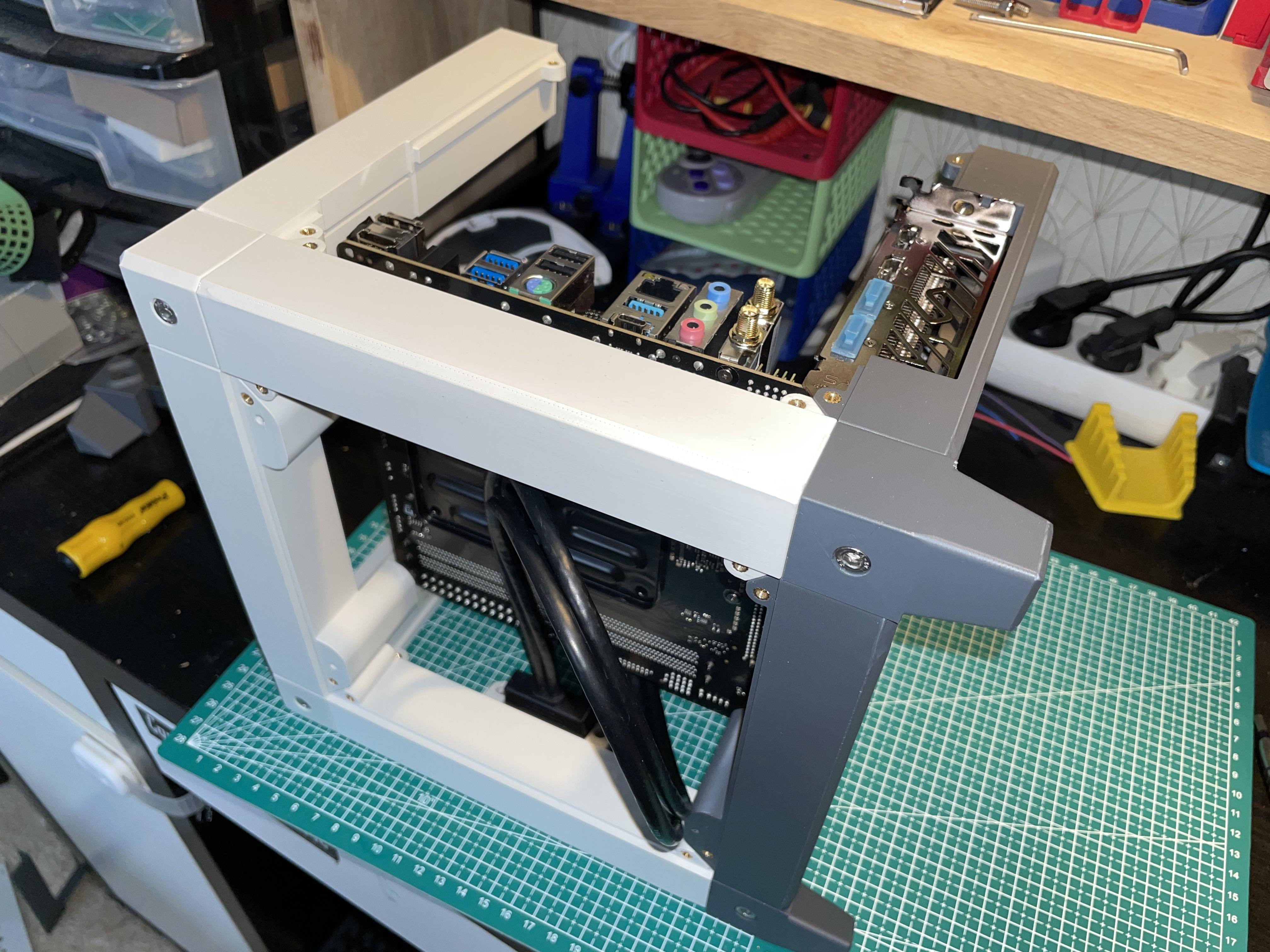

Start with the rear bottom horizontal stem. Notice the slit for the GPU bracket, and slide the stem in place. You can wiggle the GPU a little bit if necessary. It should fall right in place. Secure the bar with a 30 to 35 mm long M5 screw.
Repeat the operation with the bottom front stem. It is hollowed to receive the end of the GPU cooler. If the cooler doesn't seem to fit, try inserting the stem the other way around. The larger side is supposed to be on the right, along the motherboard. Secure the stem with a M5 screw on the side.
Install the two upper stems in the same way. Don't tighten too much the screws for now, you may need a little wiggle room when mounting the left side frame later.
Optionally, you can secure the GPU to the frame with a M4 screw through the bracket.
Finishing the Frame


Build the left side of the frame in the same way you built the right side. Once again, be mindful of the orientation of each part, and keep in mind that each stem is unique. If necessary, refer to the models in your slicer. Alternatively, you can mark every part with a small sticker note in order to tell them apart.
Install the right side on top of the rest of the structure and use the 4 remaining long M5 screws to hold it in place. Tighten the 8 M5 screws now, the frame is now complete.
Bottom Plate


Now we'll start installing the panels. Put your case upside down and install the bottom panel by using 8 M3 screws. It will help keep everything together. you can install that panel on any side you want, whether you wanna have your build plate texture visible or not.
Top Plate and Chassis Fan


The top plate will also hold the chassis fan, which is crucial for good cooling performance. It will also receive the handle, so correct installation of this panel is important.
Put the case up on its feet.
Take your 140mm chassis fan and install it in the dedicated recess of the top panel, using the self tapping screws that should be provided with your fan. Then, route the wire behind the motherboard, then plug it to the "chassis fan" connector. (refer to your motherboard manual to locate the connector) Secure the panel on the top side of the case with 8 M3 screws, making sure the two holes for the handle are located on the sides of the case.
A Handle ??


This case boasts a very nice handle to cary about. It serves actually two purposes :
- it is very "handy" (pun very much intended) and convenient to carry around
- It also ensures that the hot air exhaust will not be obfuscated bay some object. The top grille is the only heat exhaust of the design, so it is very important that it remains clear of any object or fabric of any kind. With the handle on the top, it is less tempting to leave something on
Use the two parts called "handlers" and the 2 shorter M5 screws to install the handle. The handlers must rest against the side stems of the frame to ensure the stability and the strength of the handle. The screws must go through the handlers and the dedicated holes of the top panel. They must be tightly screwed in order to prevent the handle to get loose. You can also use a drop of glue right on the thread to prevent it from loosening over time.
Be careful not to pinch the fan wire between the handler and the panel, which would cause damage to the wire (I learnt it firsthand ... don't make the mistake I did)
Power Supply


Now, leaving the PSU out of the case, go ahead and plug every power cable you need from the PSU and leave the rest hanging. If you plan to use the SATA drives, route the SATA power cable over the front of the case and leave it hanging there for now.
Install the PSU in its slot against the left side of the frame and screw it in place. If your PSU is non modular, tuck every unused cable out of the way, either on top or under the PSU. Make sure they won’t make contact against the CPU or the chassis fan. You can use zip ties in order to keep everything tidy. Also remember that the tidier your wiring will be, the more space will remain for the air to flow, so it’s important that you take the necessary time to think this through.
The Back Panel


Now install the back panel. if your motherboard has a separated I/O backplate, insert it into the housing, then place the panel on the back of the case and use 8 M3 screws to hold the corners.
2.5" Drives and Right Panel


You can install up to 4 SATA drives on the right panel. Place the drive in one of the two slots, inserting the corresponding « bumps » from the middle wall into the side screw holes of the drive, then attach the drive with 2 short M3 screws (5 mm or so) through the holes on side wall.
Repeat the operation for every drive you wanna install, then plug the power and the SATA cable. Route the SATA ribbons over to the front and connect to the motherboard.
When you're done, secure the panel with 8 M3 screws.
Assembling the Front


Install your POWER and RESET buttons on the front panel and make the necessary connections to the motherboard.
You may have to build your own switches, whether by crimping or soldering Dupont connectors to it. They must be round 12 mm momentary switches. They are quite easy to source, look on Amazon or Aliexpress to find the ones you like. For the connection, every motherboard being different, refer to your board manual to get the exact pinout.
If can also choose to use switch that include LEDs. I chose to connect the POWER button LED to the POWER indicator and the RESET button LED to the HDD Activity indicator, but this is completely optional
Once you’re sure about your pinout, connect the switches, secure them against the panel, then close the front panel and screw it down with 8 M3 screws. Be careful not to pinch the switches wires in the process.
Closing the Case


This is the final step !
Close the case by installing the left panel. Make sure no wire risks getting caught into a fan, (if necessary, Zip tie every hanging cable) that everything is tightly packed inside and that there is a sufficient air flow to ensure an effective cooling.
This case is actually quite efficient and my tests gave 94°C out of the CPU and about 67°C out of the GPU after 2 hours at full CPU and GPU load while fully closed on my configuration. I could probably get even better results with a bigger CPU cooler, but I don't have one for the moment, so this is already satisfying.
Congratulations !


Congratulations ! Your Kubic case is now ready to be turned on. Enjoy !