K-9 Crossing: Ardiuno
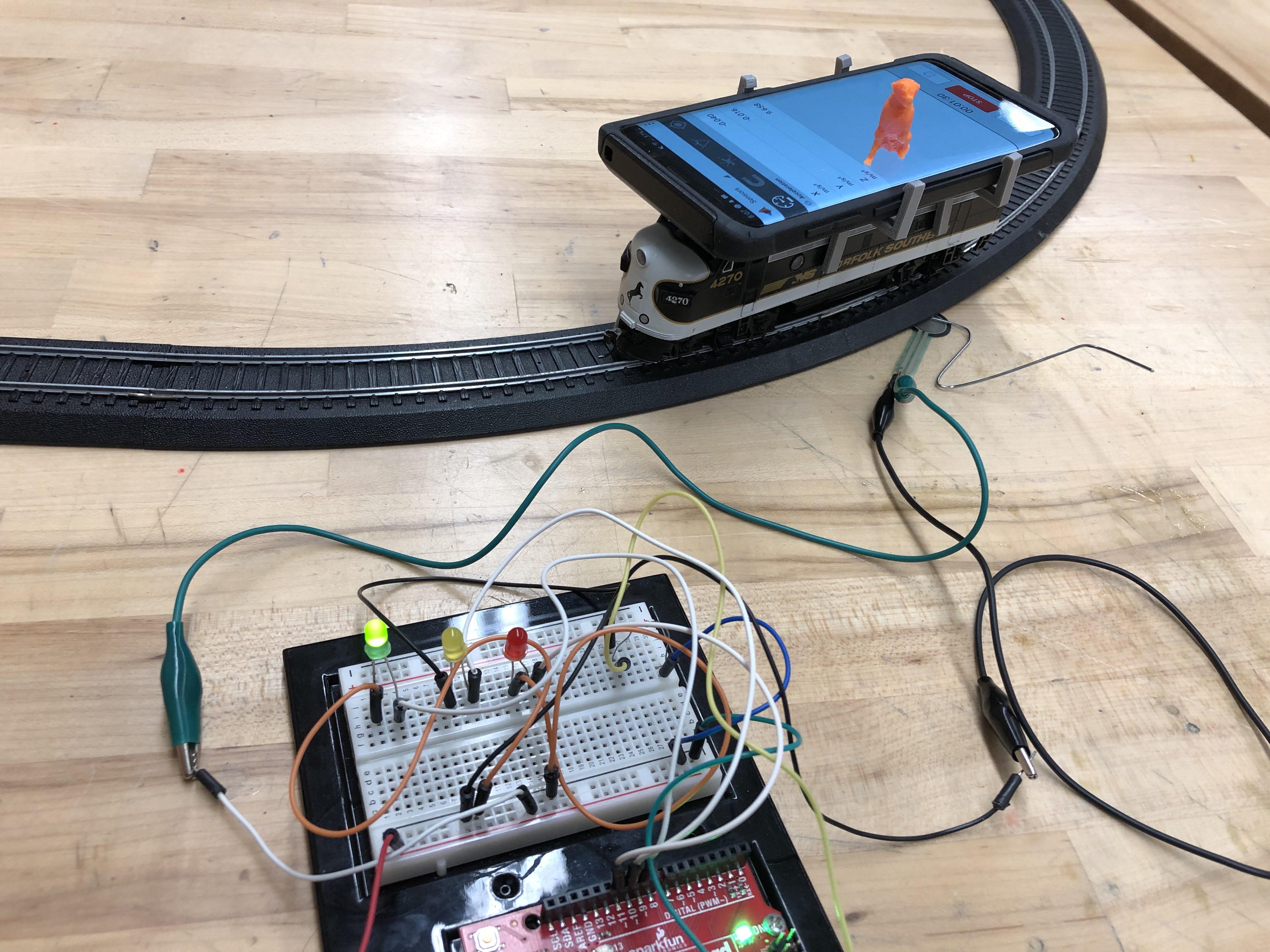
This instructable will demonstrate how to devise a system to sense acceleration and pressure of a train using MATLAB code, MATLAB mobile, and an Arduino with its various sensors/components.
Supplies
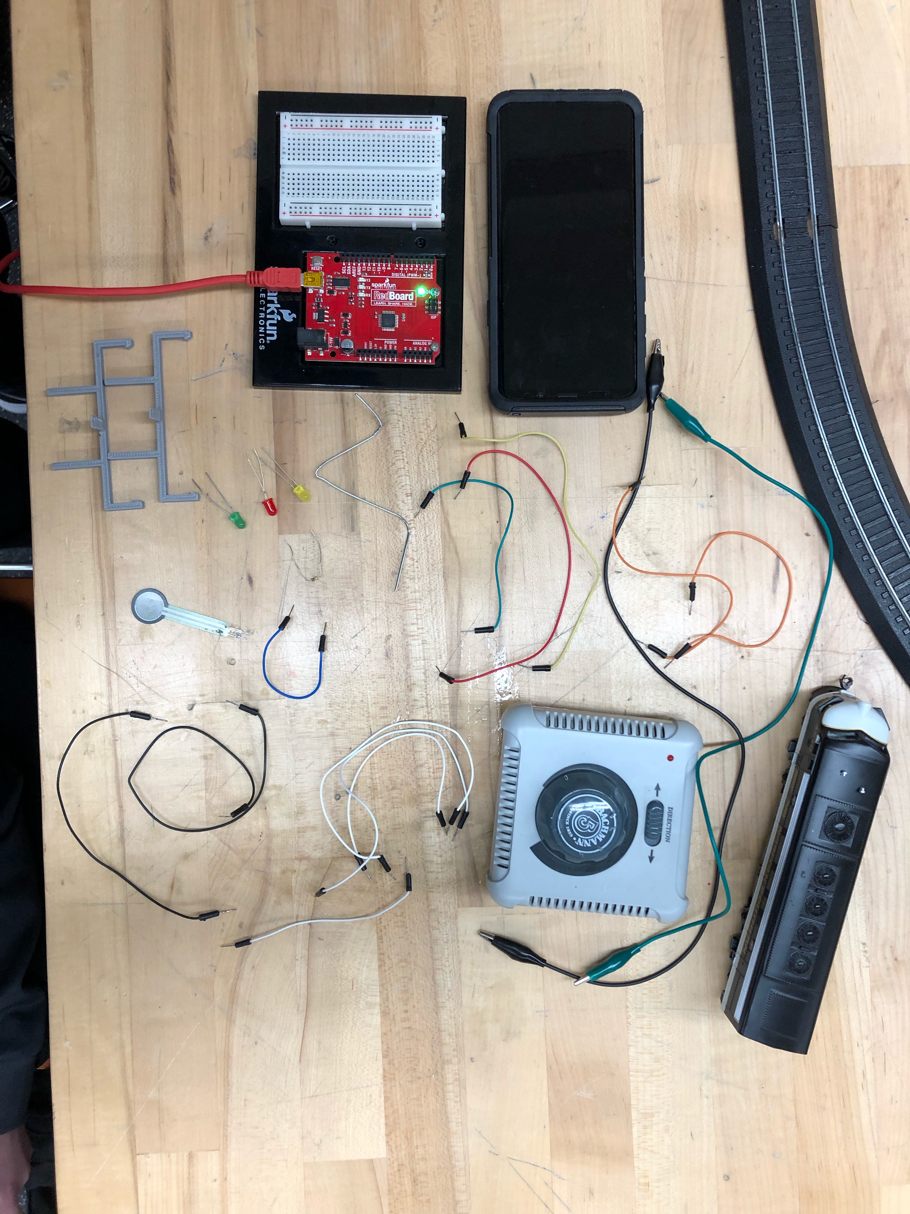
1. A computer(desktop or laptop)
2. MATLAB R2018b
3. An Arduino Red Board
4. An USB cable
5. A Breadboard
6. 11 wires
7. 2 alligator clip wires
8. A pressure sensor
9. Mobile device with MATLAB mobile downloaded
10. 3 LED lights
11. 1 330 ohm resistors
12. 3D printer for custom phone holder
13. 1 paperclip or wedge
14. 1 model train set with a voltage controller
Circuit Setup
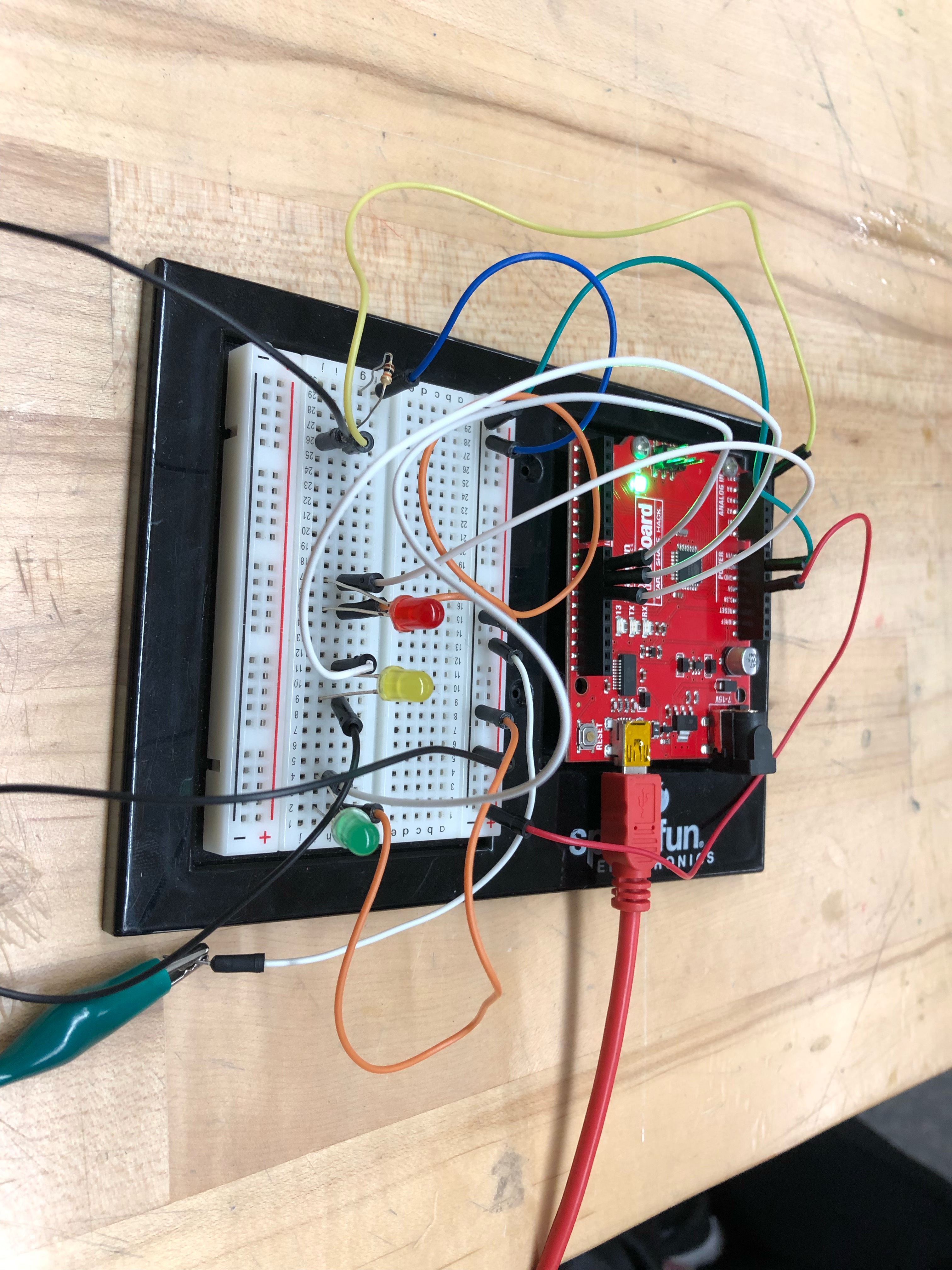
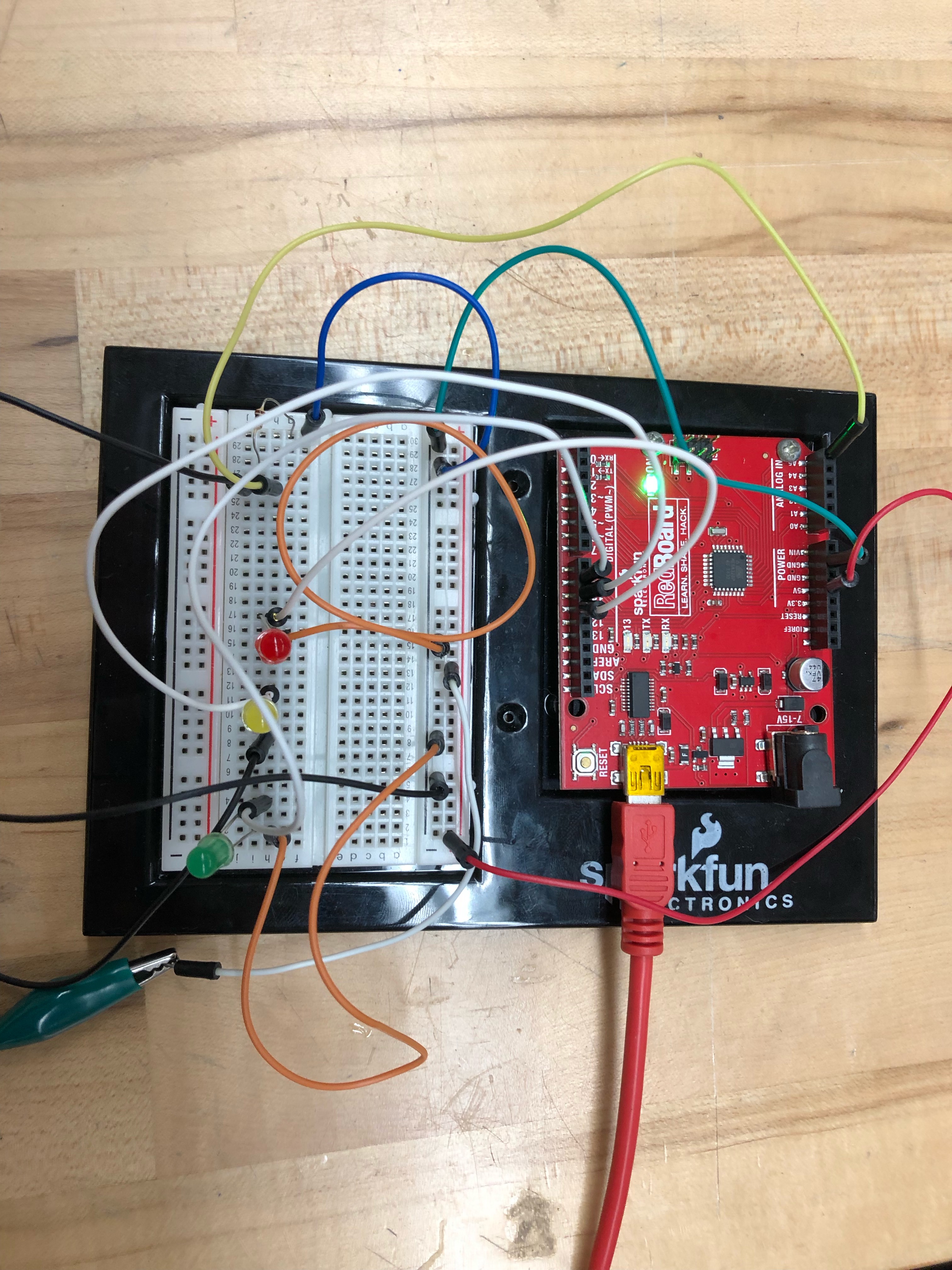
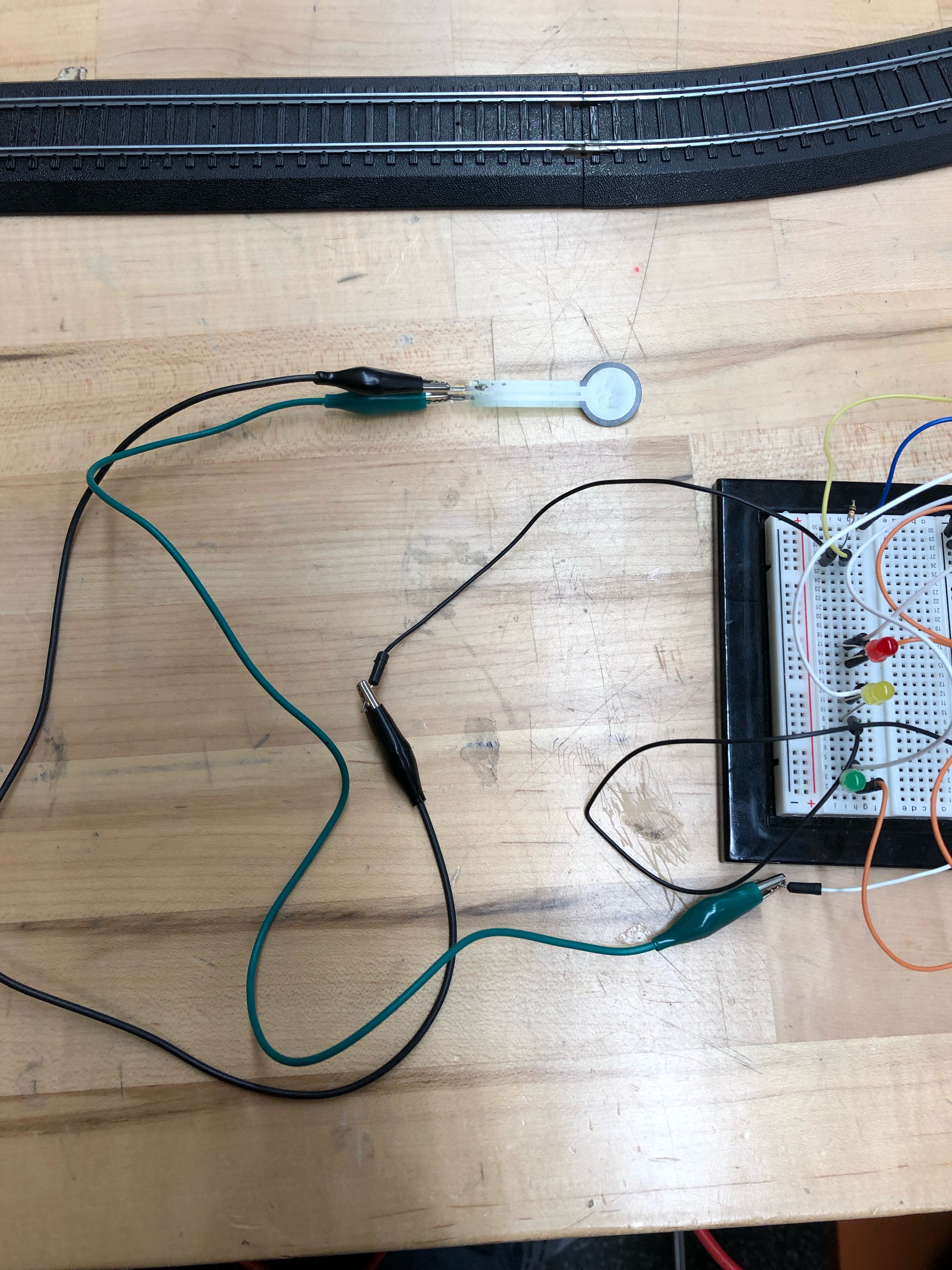
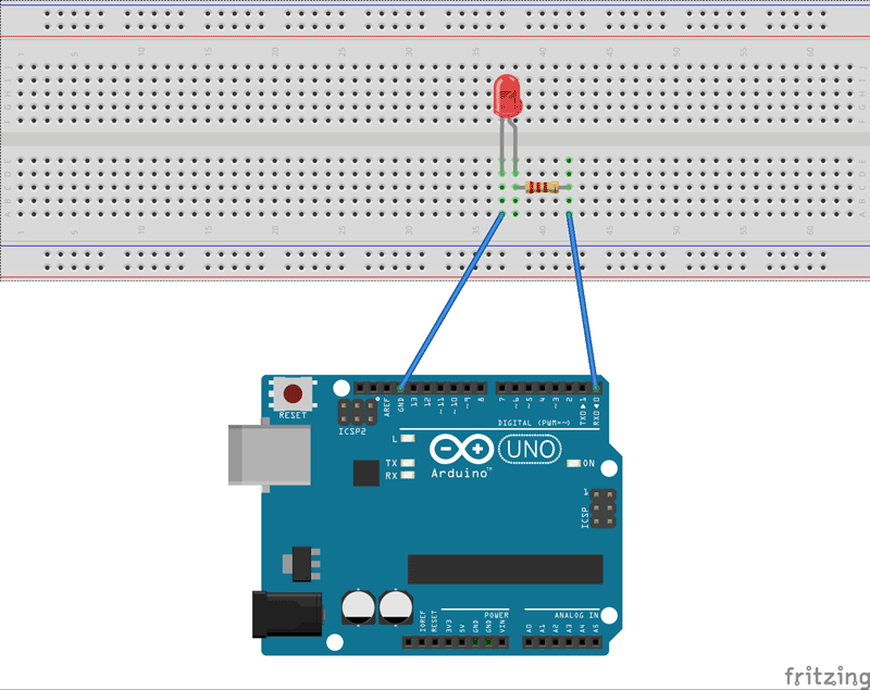
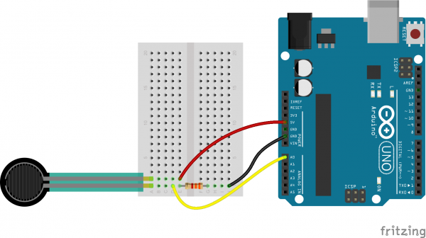
As shown in the pictures above, we have used the supplies from our list to make a complete and functional circuit. This circuit is not the most elaborate circuit out there and should be quite simple for a DIY. This is primarily to the fact that the setup of the three LED's is a repetitive process, and that the pressure sensor only uses 3 wires and two alligator clips for connection. Also, the resistors added to the circuit on the LED diagram will only dim the power/brightness of the light, and we chose to omit this for emphasis of the presence of the light activation.
Setup MATLAB Mobile Connection
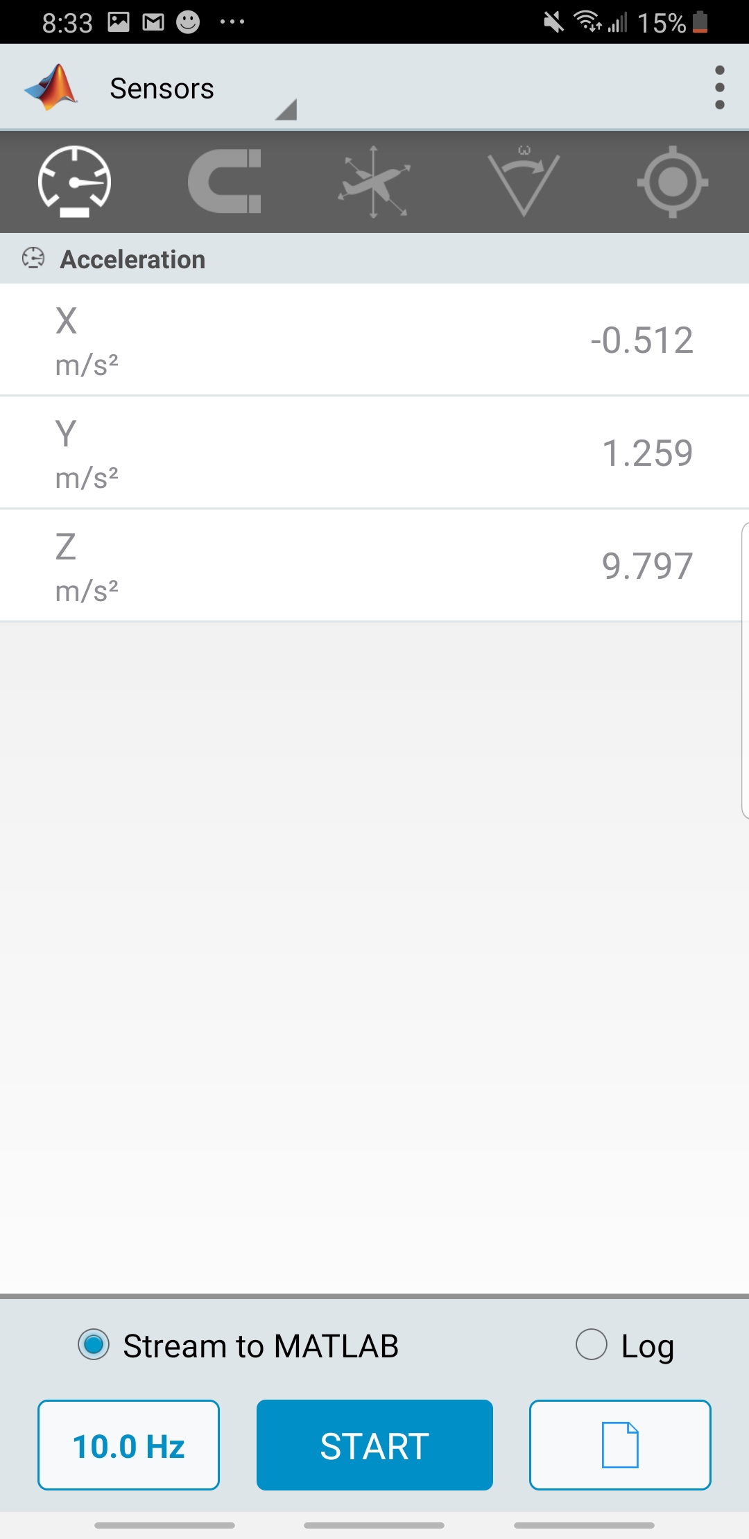
During this step, the first thing that you need to do is to download MATLAB mobile on whatever mobile device that you will be using for this project, and this application is available on both Android and Apple devices. Once the application is installed, you will have to login using you credentials. Then you must connect this device to your computer, using the tab labeled "More" -> then click "settings' -> then click "Add a computer" this should bring up the screen shown in the pictures above. After you see this the next step that you must go through is just plugging and chugging the information that it requests.
Once connected, you will need to go into the sensors tab and select the speedometer icon on the top left of the screen, which pulls up the accelerator. Now you will have to use the code developed in the next step to use the data collected from this input.
The screen shown above should be what you will see on your screen when everything is connected and set up. The numbers on this screen are always changing, which is the input harvested by the code.
3-D Printing
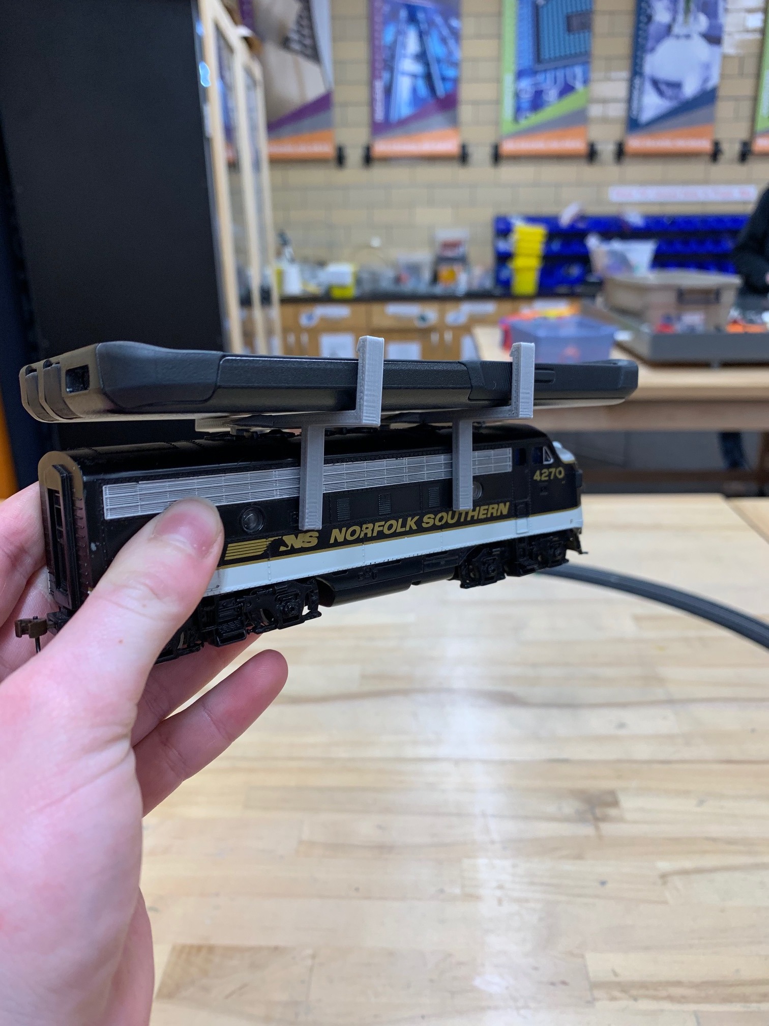
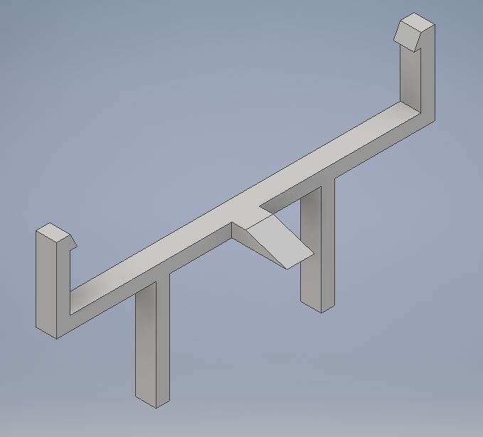
This step will require the most pre-project knowledge and yields the most opportunity for customization/creativity. We used Autodesk Inventor to create a 3-D model for an attachment for our mobile device onto our train set. This step will require measurements of both your device and the train's dimensions, which will need to be included into you 3-D design. Even though this part is not required, we also included our team mascot with is a 3-legged dog, who very much contributed to our project's success and boosted our morale; which is pictured on the the first and last step.
Logically Create MATLAB Code for Inputs/outputs
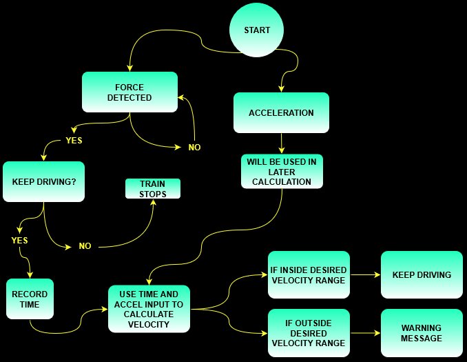
This code is designed for MATLAB r2018, and makes use of both the Arduino Sparkfun toolbox and the MATLAB Mobile toolbox. The following code is written assuming the Arduino is connected to port 6 (COM6) and assuming that the mobile device running MATLAB mobile is connected to the computer. Also you must run the first line of the code the first time that you run the code, but all the subsequent runs after it is recommended that you suppress this line with a "%" in front of this line.
Code:
a=arduino('com6','uno')
connector on
m=mobiledev;
m.Logging = 1
%% Initialization
time = 0;
v0= 0;
x= 129; %length of the track or distance between sensors if multiple sensors
max = 12; %set maximum velocity
min = 7; %set minimum velocity
%% Main Code/While Loop
while time < 500
pos=readVoltage(a,'A5'); %reads the voltage across the forse senor
acc=m.Acceleration; %writes the values from the acceleration sensor into variable acc linAcc=sqrt((acc(:,1)).^2)+(acc(:,2).^2); %calculates the linear acceleration of the train
time=time+.1; %increases the time variable by 0.1
pause(.1); %pauses the code for 0.1 seconds, then continues the loop
Acceleration_Time=[linAcc,time]; %writes the time value and linear acceleration into a matrix writePWMVoltage(a,'D11',0); %resets the value of pin D11 to 0V
writePWMVoltage(a,'D10',0); %resets the value of pin D10 to 0V
writePWMVoltage(a,'D9',0); %resets the value of pin D19 to 0V
if pos > 2 %denotes the value the force sensor output when the train passes over it
disp('Train Incoming: Clear the Tracks!')
velocity = sqrt(v0.^2+2.*linAcc.*x) %calculates the velocity of the train
if velocity > max %starts the if loop to tell if the speed of the train is within desired values
writePWMVoltage(a,'D11',3) %writes voltage of pin D11 to 3, lights up the red LED
msgbox('Too Fast!','Speed','modal') %displays message: Warning! Too Fast!
disp('Warning: Too Fast!')
elseif velocity < min %denotes if the speed of the train is under the set values
writePWMVoltage(a,'D10',3) %writes voltage of pin D10 to 3, lights up the yellow LED
msgbox('Train Too Slow or Stopped!','Speed','modal') %displays message: Warning! Too Slow or Stopped!
disp('Warning: Too Slow!')
else %if the train has any value that is less than the max or more than the min
writePWMVoltage(a,'D9',3) %writes voltage of pin D9 to 3, lights up the green LED msgbox('Good Speed, Keep Going!','Speed','modal') %displays message: Good Speed, Keep Going!
end
end
end
Test Outputs and Logic
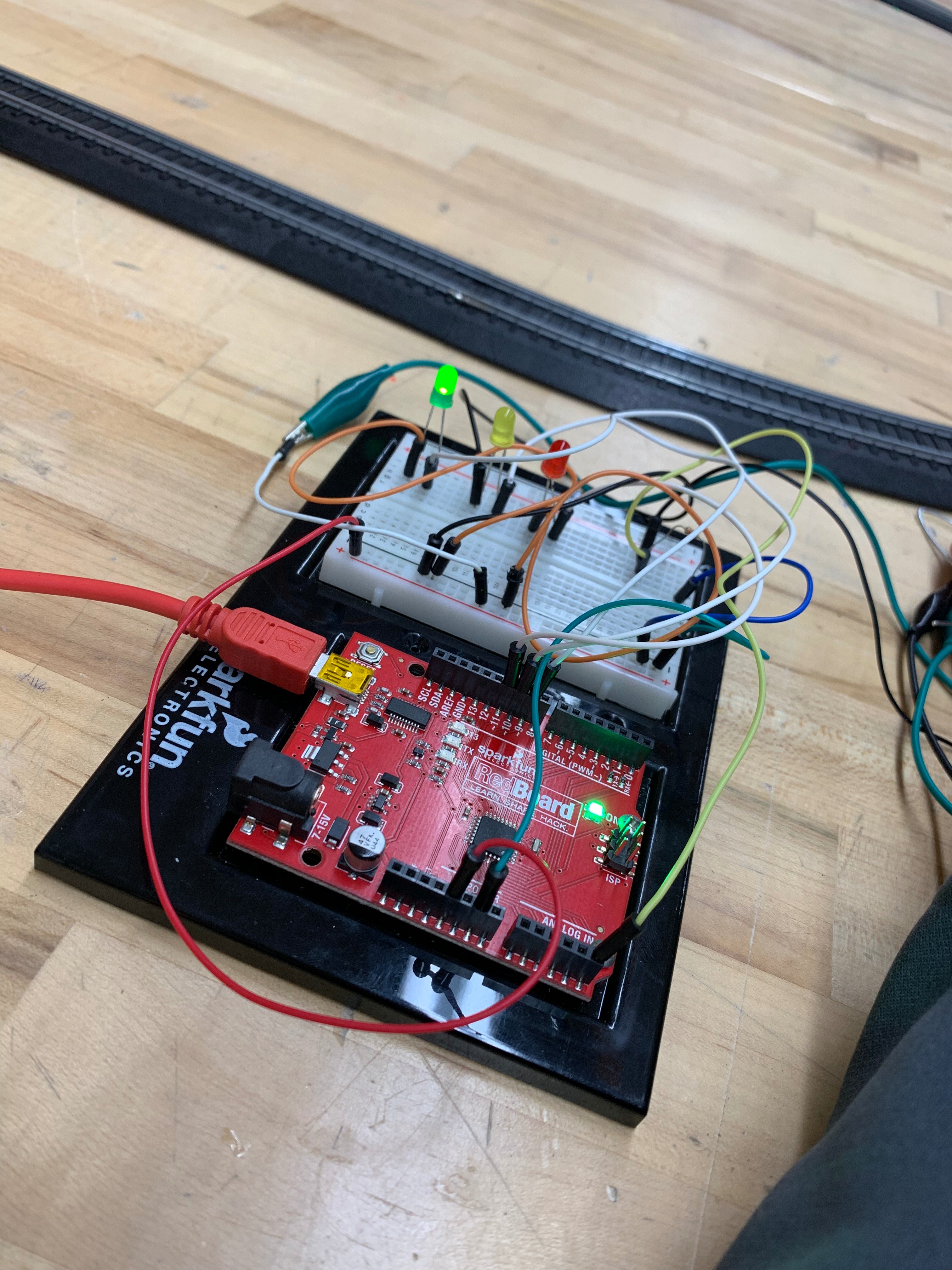
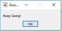
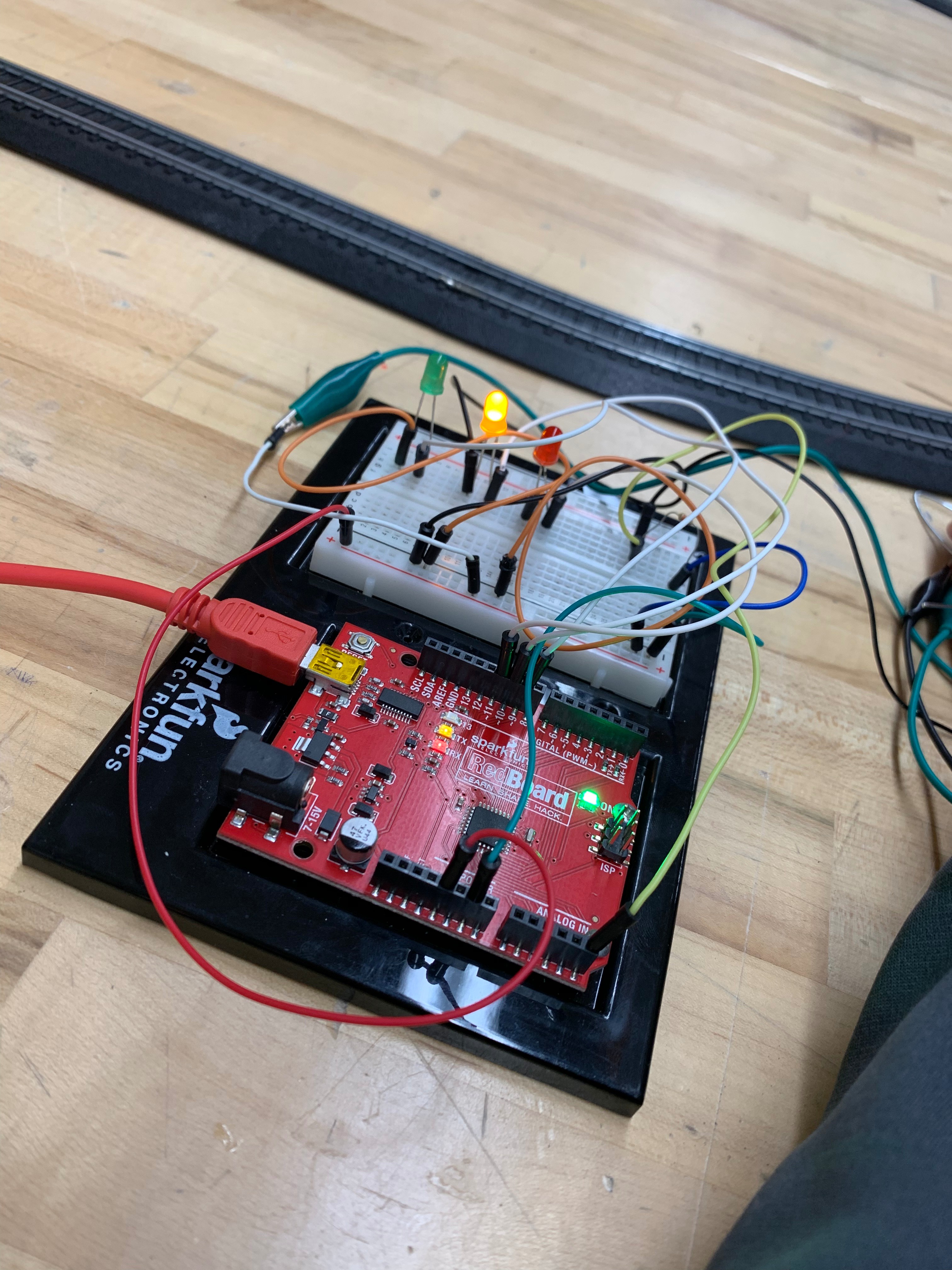

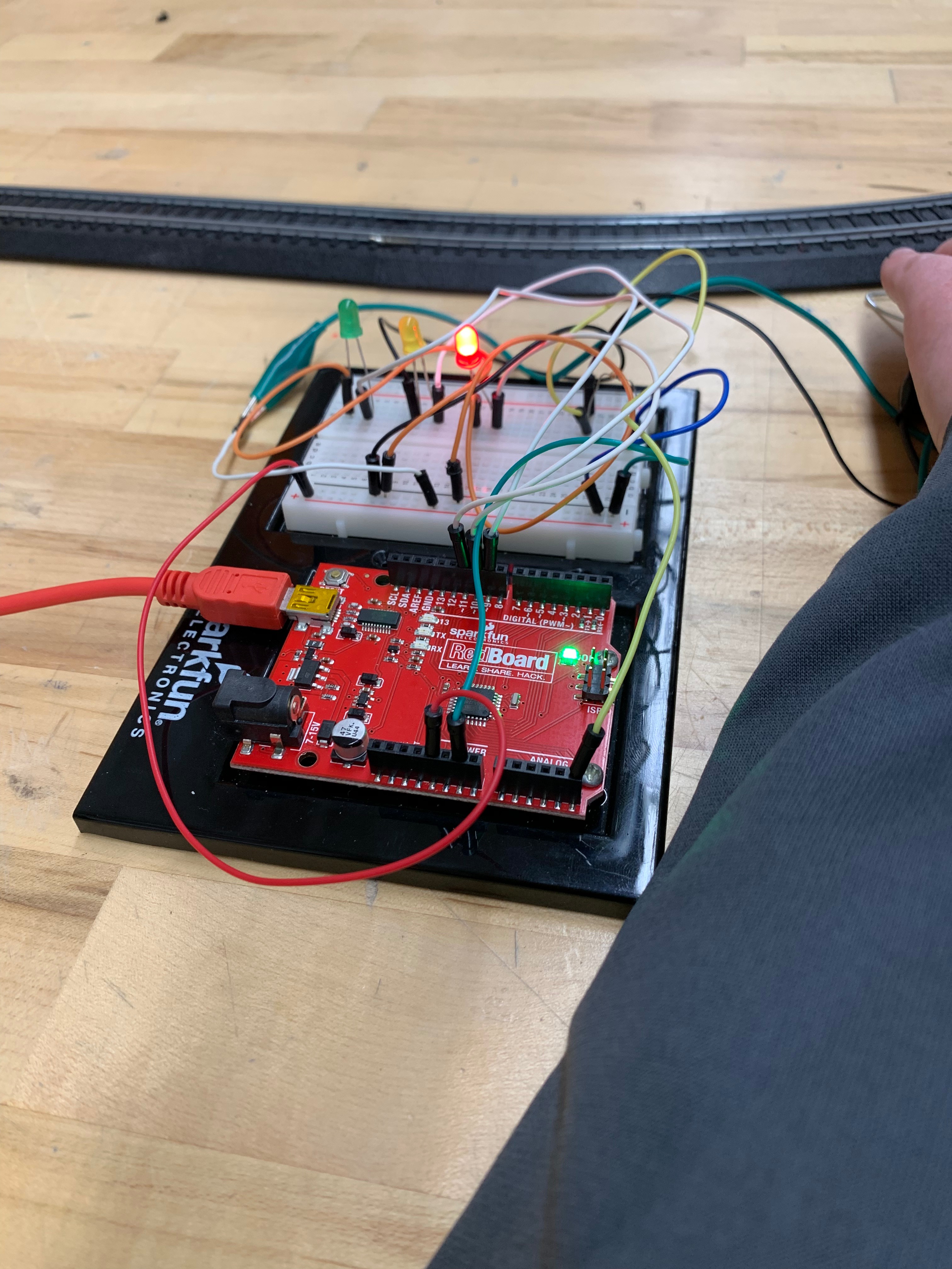

The code should be separated into sections as previously documented, which will make this step easiest. Individually, run each section of the code and look for error messages. In the pictures above, each section of the code will be connected to the different inputs and outputs, and each one should be test separately to make sure that they work. When this is complete, you can run the code as a whole.
While the code is running, the different warning boxes will pop up corresponding with the according light. This output is determined by the rate train is accelerating.
Recognizing Sources of Error and Hardship
We would like to recognize some of the problems that we encountered during our journey on this project. One problem was that MATLAB mobile can be very buggy sometimes, and specifically with giving you an error message when you try to connect to a computer. Another problem that we encountered was with operating the train, and getting it to be steadily aligned with the track. The last main problem that we encountered was the fluctuation in output given by the pressure sensor, and this could be caused by wiring problems, sensor damage, or trouble centralizing the force onto the sensor.
Connect to Train and Enjoy!
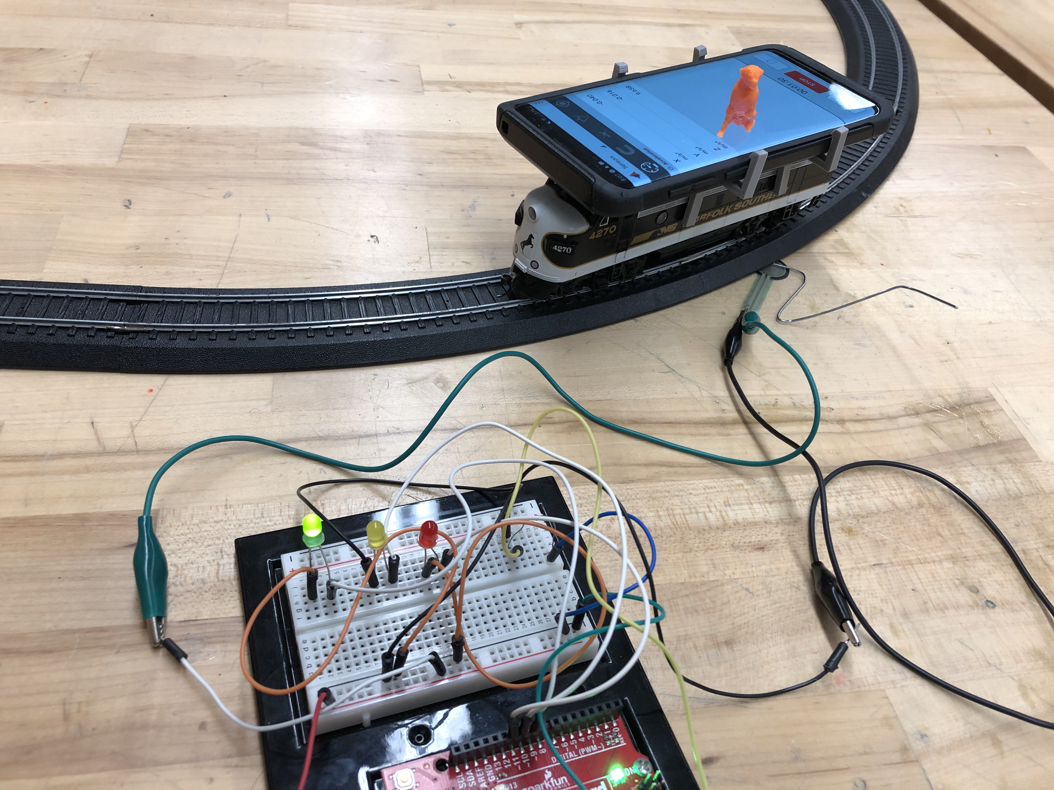
This will be the easiest part of your day with the most payoff, that is if you love trains like us. Assuming that you have the train all set up, you just have to attach your mobile device to the train and position the pressure sensor under the tracks with your wedge(paperclip) as shown. Finally, you run your code and enjoy your hard work come to life!