Jumbo CNC Laser Cutter/Etcher Designed With Autodesk Fusion 360
by SeanMiller in Workshop > CNC
18049 Views, 252 Favorites, 0 Comments
Jumbo CNC Laser Cutter/Etcher Designed With Autodesk Fusion 360
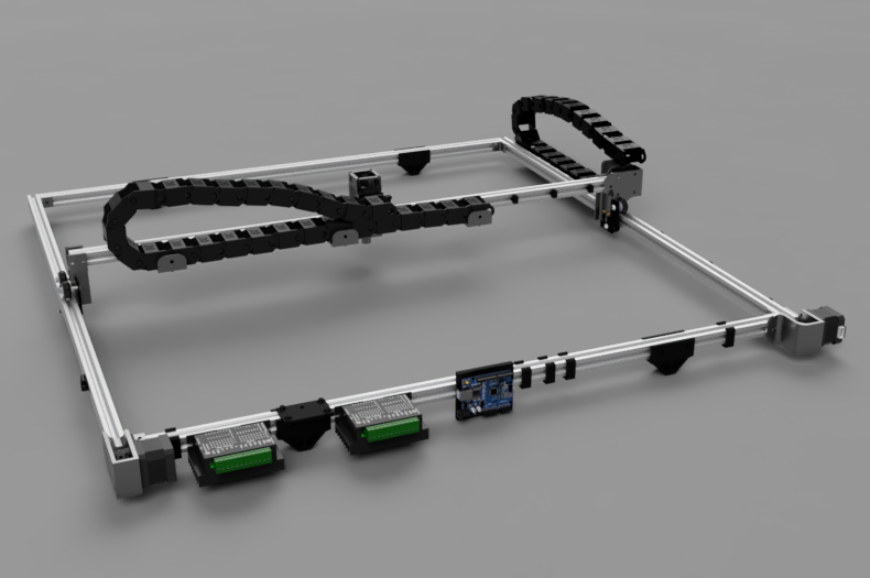
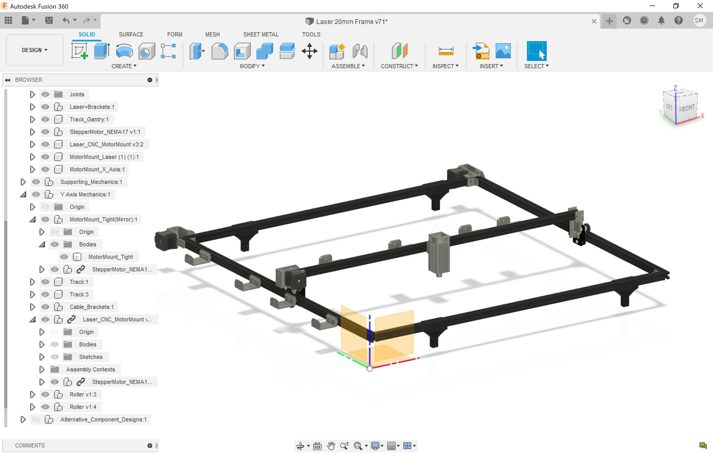
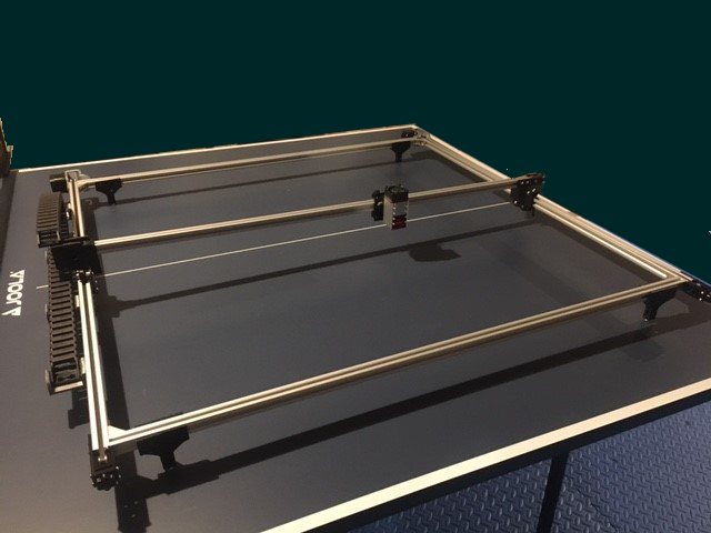
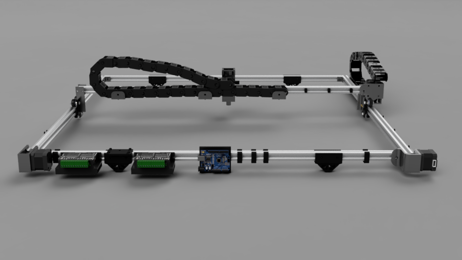
With this Instructable, not only will you build the largest and lightest 7.5W Laser Etcher you've ever seen in action, you will emerge an engineering stallion with your honed Autodesk Fusion 360 skills. My son and I exhausted all the greatest features of Autodesk Fusion 360 for rapidly prototyping mechatronic designs including model imports, mechanical design, assembly joints, PCB design, PCB enclosure design, CAM, G-Code Exports, 2D Drawings, exploded views, and Photorealistic Rendering.
This step-by-step tutorial will give you mastery of Autodesk Fusion 360 while also giving you a one-of-a-kind, beast of a CNC machine that allows for marking large sheets of fabric to make your own clothes or laying out trace lines for school poster projects. You'll also be able to easily cut 1/4" hardwood and burn masks for your chemically etched PCB projects. Throughout this build, my son will bestow his 10 years of Autodesk experience that he developed as Autodesk Fusion 360 evolved dating back to the Autodesk123 days.
Build Notes: This CNC was so big - we rewarded ourselves with a ping pong table to hold it!
Supplies
- Autodesk Fusion 360 Design File
- Frame: 1000mmx20mmx20mm Extruded Aluminum T-Slot (5 pieces)
- Motors: Nema 17 Stepper Motors 17HS4401 (3 each)
- Laser: 7.5W Optical Power (1 each)
- CNC Wheel Plate: For the Laser Mount (1 each)
- CNC Wheel Plate: For the Gantry (2 each)
- Stepper Driver: 4 Amp (2 each)
- Driver Power Supply (24 4 Amp)
- Cable: 4 Conductor 20AWG (~20ft)
- Cable Management: 15mmx30mm Drag Chain (2 each)
- CNC Brains: Arduino UNO (1 each)
- Timing Belts with Pulleys (1 kit)
- Belt Tensioners: 5mm pulleys (3 each)
- 3D Printer Filament: PLA (1kG)
- T-slot Brackets: 6mm Corner Brackets (1 pack)
- Miscellaneous: ProtoBoard, hookup wire, connectors of choice
- Autodesk Fusion 360 File: Raising Awesome Github
- 3D Printed Parts:
- Legs (4 ea)
- Cable Bracket (6 ea)
- Side Cable Clip Large (6 ea)
- Side Cable Clip Small (3 ea)
- Laser Motor Mount (1 ea)
- Laser Gantry Mount (1 ea)
- Left Motor Mount (1 ea)
- Right Motor Mount (1 ea)
Obtaining Autodesk Fusion 360
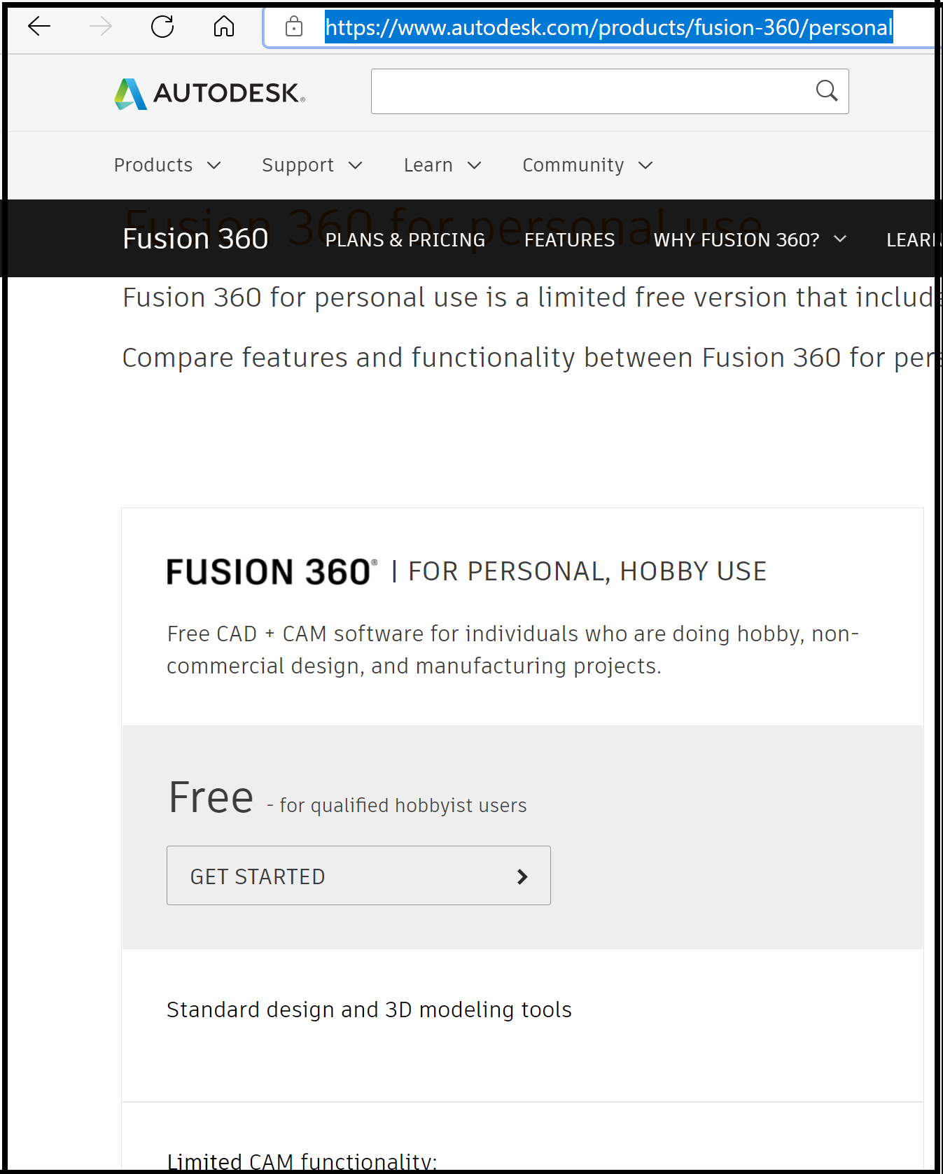
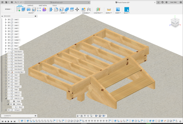
First, before you build this CNC or anything for that matter, you need to download Autodesk Fusion 360.
Autodesk Fusion 360 - coupled to some basic power tools and a 3D printer - will absolutely change your life. Nothing will be out of reach - whether your interests are with making nice furniture, home theater speaker design, IoT mechatronics, or anything else you dream up - it all starts with Autodesk Fusion 360. In fact, every project we do (about 3 big ones a year) starts with a full Autodesk Fusion 360 design - before we even pick up a screwdriver.
- Visit Autodesk.com and download the personal addition.
- Create your account per their instructions.
- Launch it!
Build Notes: This was one of our fastest ever builds because of two things: Autodesk Fusion 360's "insert McMaster CARR Component" and Grabcad.com. Between these two sources, 80% of the component design was simply placement of predesigned parts!
Review Our Top 10 Tips for Autodesk Fusion 360
Before we get too deep into this build, we'd like to bestow our top 10 tips for using Autodesk Fusion 360. This will allow you to have the most efficient overall design cycle. These were developed with 10 years of weekly use.
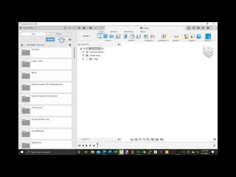
- Always Create a New folder for your projects
Once you are bit with the Maker bug, you'll find yourself starting a lot of designs. Those designs may include 2D drawings so you can head to the garage with a printed copy of dimensions. Or, they may have a complete PCB design suite including the schematic, board layout, and a 3D board with enclosure. All these files can bloat a root directory. So, step 1 is always create a new folder.
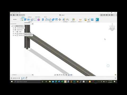
- When in a new design file for a project, immediately create a new component and start working from it versus the root of the default hierarchy.
Most often when you start a file, you aren't doing so to design a single component. Rather, your designed components are born from your projects. So, its important that component structures contain their sketches and other attributes. This won't be possible if you start hacking away in the root structure. So, as soon as you are ready to start, right click on the root node at the top of the hierarchy and select New Component.
- Pick a naming convention for your Components and their Bodies.
If you adopt a convention for naming, it will allow things to lay out the parts alphabetically such as on 2D drawings. Your eye will quickly navigate the structure. For bodies, its tempting to just leave them called Body1, Body2, etc - but that shows with poor quality on 2D drawings. We typically name bodies with Body_xxxx_yyyy, where xxxx is the component and yyyy is the description of that particular body.
- Set your first component's front to truly point to the front.
Sometimes you'll jump in and quickly design up a part and you have the front point up or to the back. Before adding more components, rotate it to the front. It will save you trouble later with your 2D drawing generation.
- Use the Move and Snap feature over eyeballing alignment.
We don't know when this feature showed up, but we were a few years in before we realized it was there. It's a game changer. When you need to separate bodies or components to rest against one another, we used to simply zoom in and eyeball it. Instead, in move mode, click the face that will rest against the other part. The gizmo should reflect your selection. Now, drag the arrow away from the other part to give you full view of that other face. You'll need to rotate your project to get a view of the other face so you can click it. When you click it, you will snap right to it perfectly. This works for 3D PCBs as well.
- Get a digital caliper and always validate borrowed models with the Inspect Measure tool.
You can use a canvas to trace a picture of a part, but it will only get you an inaccurately modelled part that will result in many issues for assembly. Instead, get you some digital calipers and measure every detail of a part you are modeling.
If you borrowed a model, be sure to hit the "i" key to measure critical dimensions and check against your real world part.
- Use pictures for texturing versus adding faces of stock textures.
When making a full design file, you may not need every face for every object - particularly if the component is solely a reference object. You just need the critical dimensions that you will reference to set the design of your component.
However, I'm sure you'll want a pretty render. To get a photorealistic render with minimum geometry, simply take a head on picture of the real world surface and upload it as a material using Modify-->Manage Materials. Taking this approach, you can consolidate an entire back of a house with a rectangle.
- Make a Prefab Folder
Your projects will most likely develop various components that could be used in future projects. Things like bearings, switches, and gears can take time to design and will show up often in your projects. If there is a chance to use a component again, right click it in the hierarchy and choose "Save As" to a folder called Prefabs. You can then drag and drop it in to future designs and updating it in the prefab folder will update it everywhere!
- Get the App
There is a companion app for your phone. You can see and share all your design files from your cloud storage. If you have buddies or anyone asks you about what you are up to, you'll have everything right in your pocket.
- Never delete a body or component - use Remove instead
Autodesk has an amazing system of using time to your favor. Parts are built from references and offsets of other parts and sketch objects. If you decide to delete something, you'll break that feature and regret it soon. Instead, right click-->Remove to turn it invisible and preserve its contribution to the design.
Build Notes: We chose these tips because over the years, we never had them jump out at us in tutorials by others. With frequent use of Autodesk Fusion 360, we apply of them all the time to stay efficient. We'd love to hear your tips in the comments below!
Basic Mechanical Assembly - Importing From McMaster-Carr

To jump right into this design, you can download our Autodesk Fusion 360 file here. With it, you can export and print the 3D parts. Then, to build the CNC, you just need some Allen wrenches and a screw driver.
To learn to design for your self, let's do some basic insertion of component and alignment. Once you have this down, it's easier than assembling a Lego kit. We'll start by designing the frame of the CNC Laser Etcher.
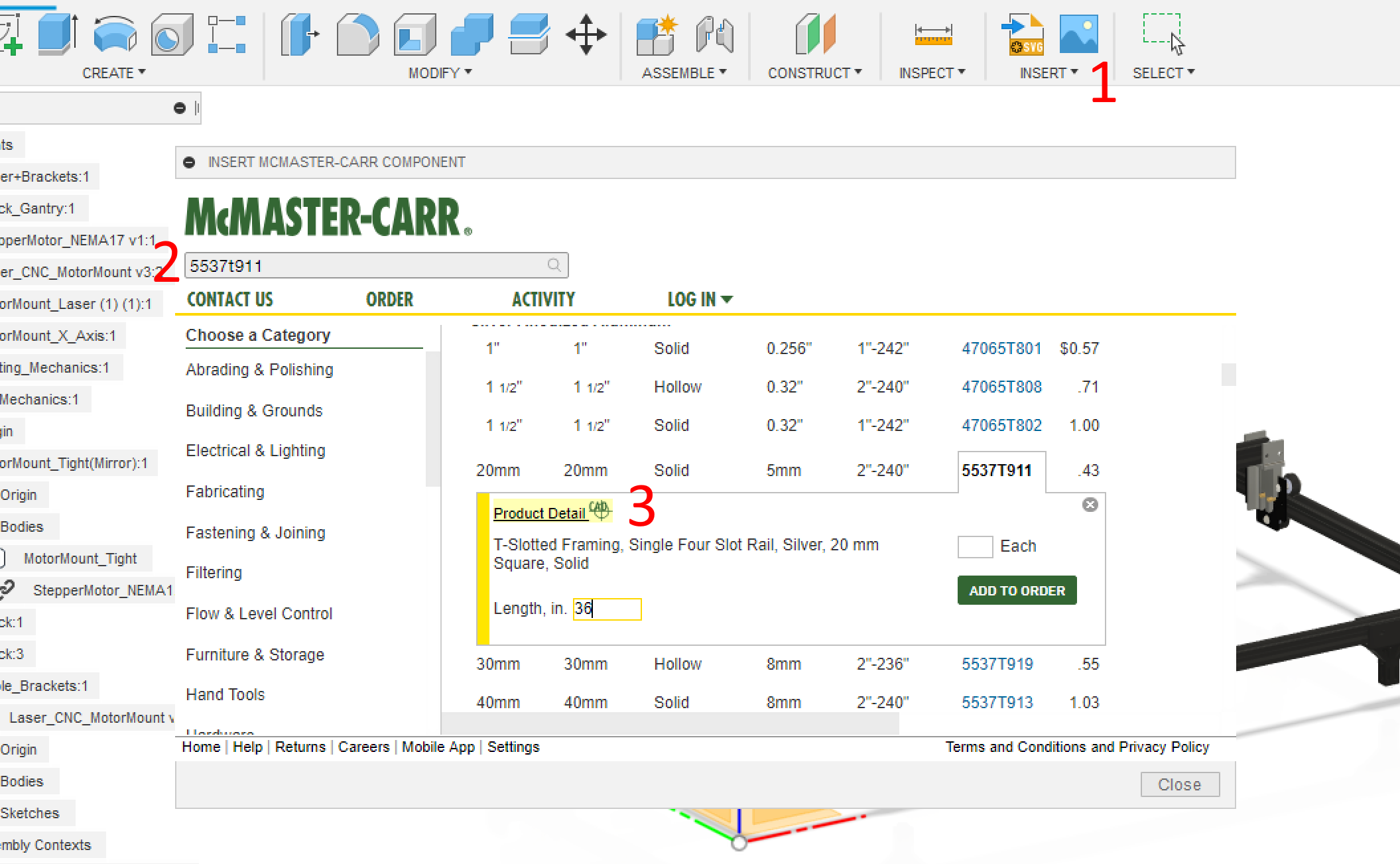
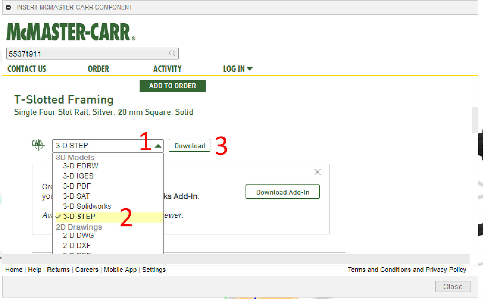
Referring to the screen shots above, try this:
- Click Insert-->McMaster-Carr Component
- Type 5537t911 in their search bar
- Click the Product Details icon
- Scroll to find the 3D CAD model download and download as shown in the screenshot above.
The above video demonstrates this process. It will land you some T-track that you can then extrude out to 1000mm as shown in the video. Repeat the process for McMaster-Carr # 5537T935 to get the corner brackets.
GrabCad.com is another essential source for designing. Many things such as the Arduino UNO, Raspberry Pi, and T-Slot Track components have long been designed and shared there. We'll import one of those files next.
Basic Mechanical Assembly - Importing From GrabCad.com
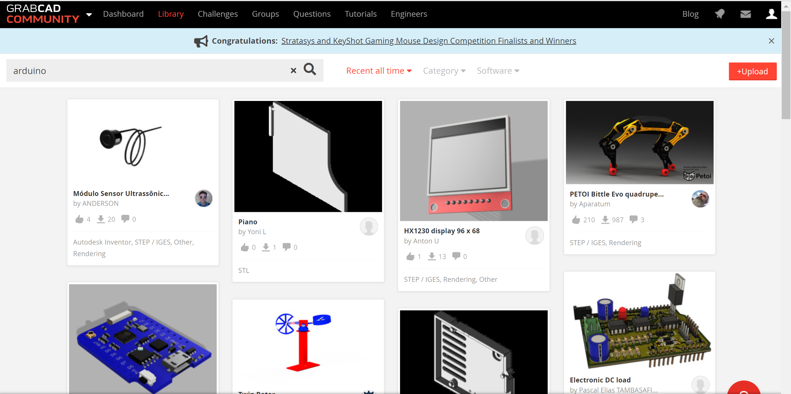
GrabCad.com is a community that loves to share their 3D designs. Most of the time, consumer products have already been modelled such as Arduino's and stepper motors. So, if its not in the McMaster-Carr catalog, chances are, you'll find it at GrabCad.com.
Procedure for using GrabCad.com:
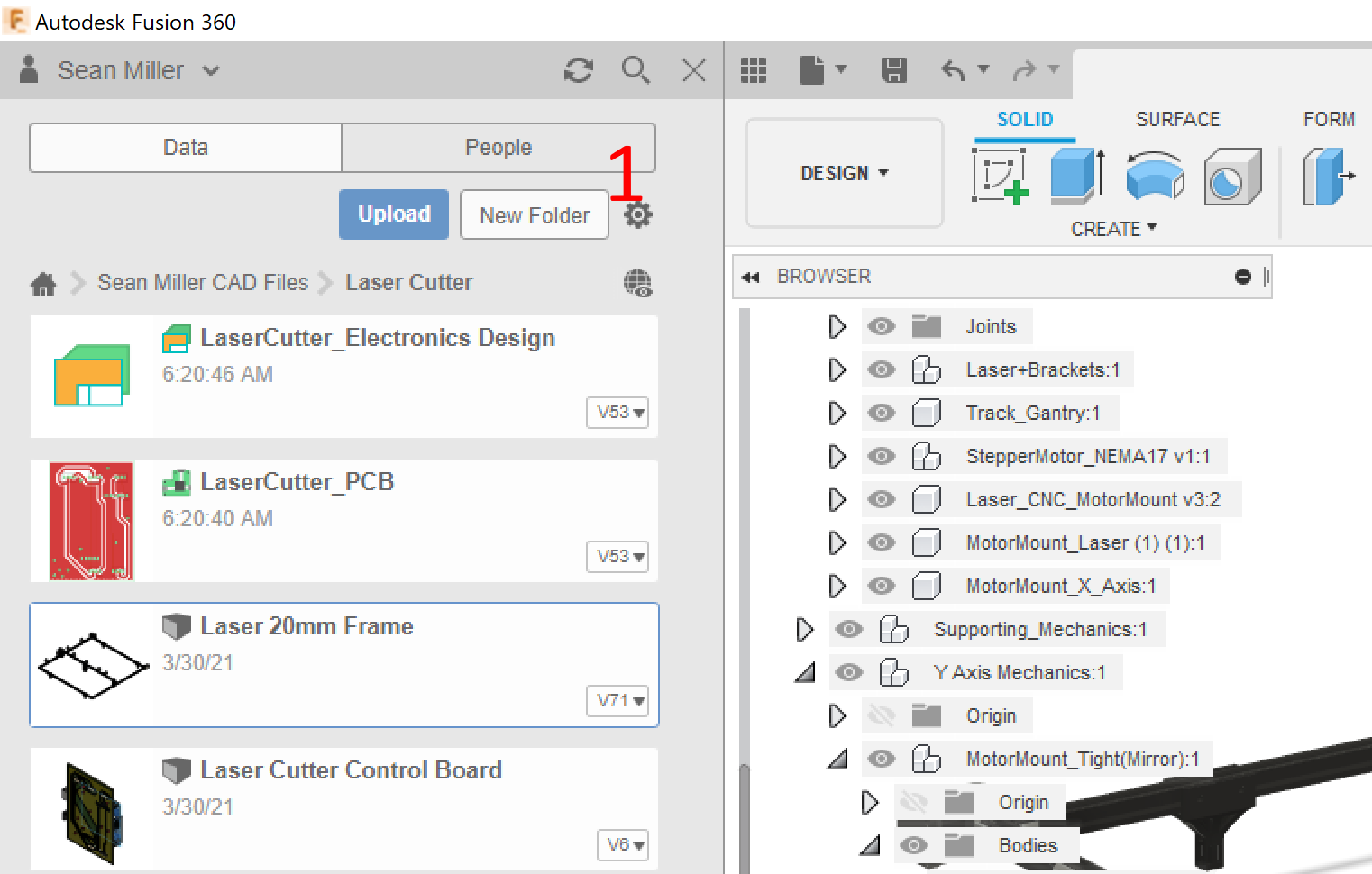
- First, create a new folder called Prefabs in Autodesk Fusion 360. See the screen shot above for reference.
- Visit GrabCad.com and search out an item of interest such as a Nema 17 Stepper Motor.
- Download the files to your local drive and unzip them.
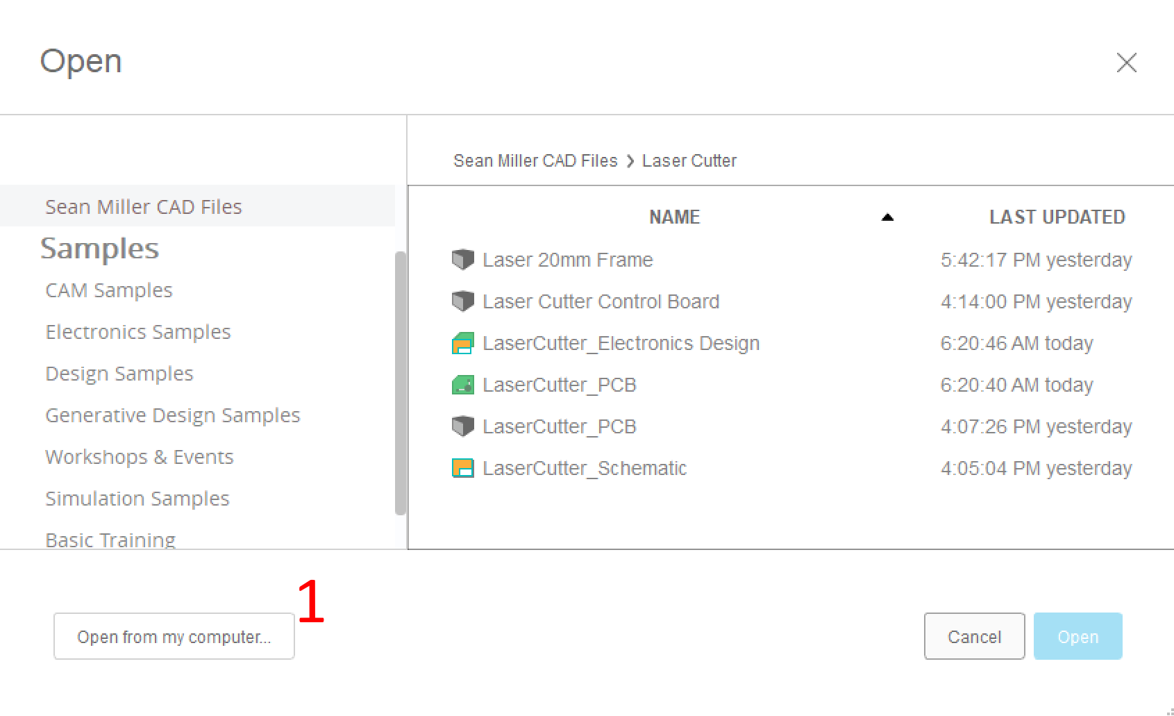
- In Autodesk Fusion 360, Flick File-->Open-->Open From My Computer and locate the file you unzipped.
- Autodesk Fusion 360 will accept many file formats, but if it says it can't, see if GrabCad offered other versions. The formats of STEP, STL, OBJ, FBX, and SolidWorks have always worked for us.
- Once the file imports, be sure to save it to your PreFabs Folder
- Once saved, you can now simply drag and drop it into your future designs. Updating that master file will update all your associated design files, too!
The extra items we used to visualize our build can be downloaded on GrabCad.com here:
Build Notes: When we first found GrabCad.com, it felt like we were cheating by not making our own models. We learned that - heck no - we are part of a global community working towards a greater good. Leverage what other people have made and free yourself up to design and contribute the things they haven't. In ten years, we'll have every object on earth in there!
Advanced Mechanical Assembly: Joints
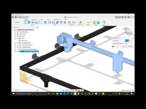

To ensure your components will travel without crashing, it's good to assemble it in Autodesk Fusion 360 with joints. You an then can simulate its movement. This will let you adjust your 3D models and how it all fastens together before you waste any elbow grease.
To start, you'll want to join any components that will travel together as a Rigid Group. This doesn't affect their geometries, just how they travel together. For example, for a Rigid Group, if you move one component, they will the rest of the rigid group will move with it.
For the CNC gantry (the Y axis movement of the laser), you'll want to make a slider group. Take a look at the videos above to see how to do this in Autodesk Fusion 360.
Rendering the Design
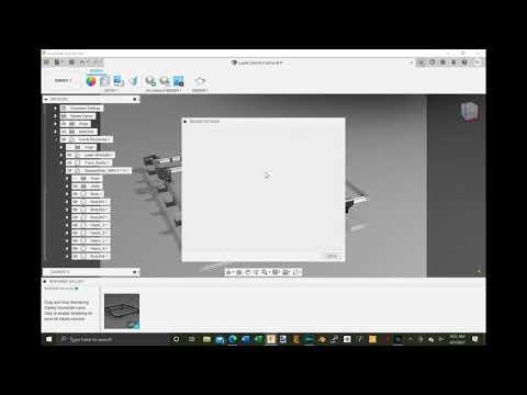
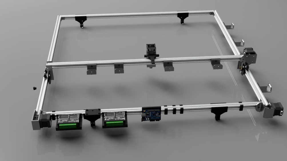
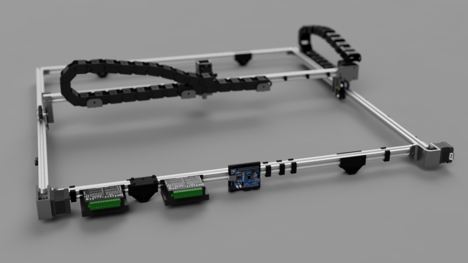
Autodesk Fusion 360 allows you to design and simulate the function of your project, but also it allows you to perfect its form. You can do this with the Render Workspace.
In the Render Workspace, you can put your project into an environment or use the canned environments available. Then, you can render it with photorealistic lighting and shaders to visualize how it will look. To do this, click the Render workspace and play with the options. When you have it the way you like it, click the render icon. See the video above for a demo.
3D Printing the Parts
You'll find the links to the 3D parts list below and in the Supplies section of this Instructable. If you have opened our Autodesk Fusion 360 file, you may also modify those parts and export them as STL for printing. Try adding your name to a motor mount for fun.
To build this giant CNC, you'll need to 3D print the following parts with at least 10% infill. By the nature of the parts, you don't need any more infill than that as you'll find them very strong with PLA or ABS.
If you already have the other supplies on hand, all that is left before we assemble is printing the following 3D Printed Parts:
- Legs (4 ea)
- Cable Bracket (6 ea)
- Cable Clip (6 ea)
- Laser Motor Mount (1 ea)
- Laser Gantry Mount Laser Gantry Mount (1 ea)
- Left Motor Mount (1 ea)
- Right Motor Mount (1 ea)
Also, if you are designing your file from scratch in Autodesk Fusion 360, then you can also import these files using the same technique as you did to import from GrabCad.com in the previous section.
Build Notes: We first thought that there was no way we could make an etcher so big with such small track and small parts. But we found every part was super light. In turn, we stuck with the minimalist design and are very happy with the results as it is easy to move around and store.
Designing and Making a Circuit Board
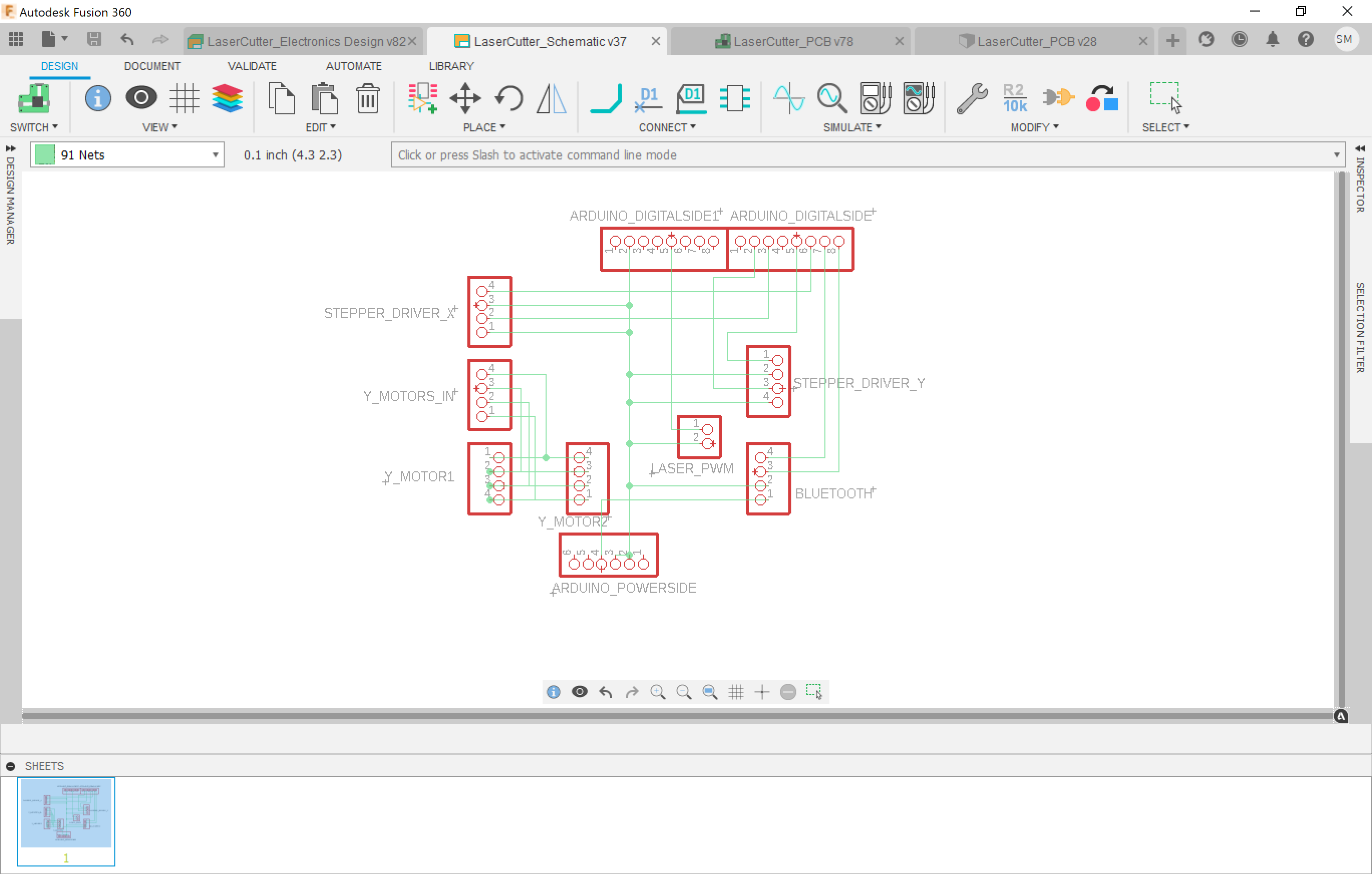
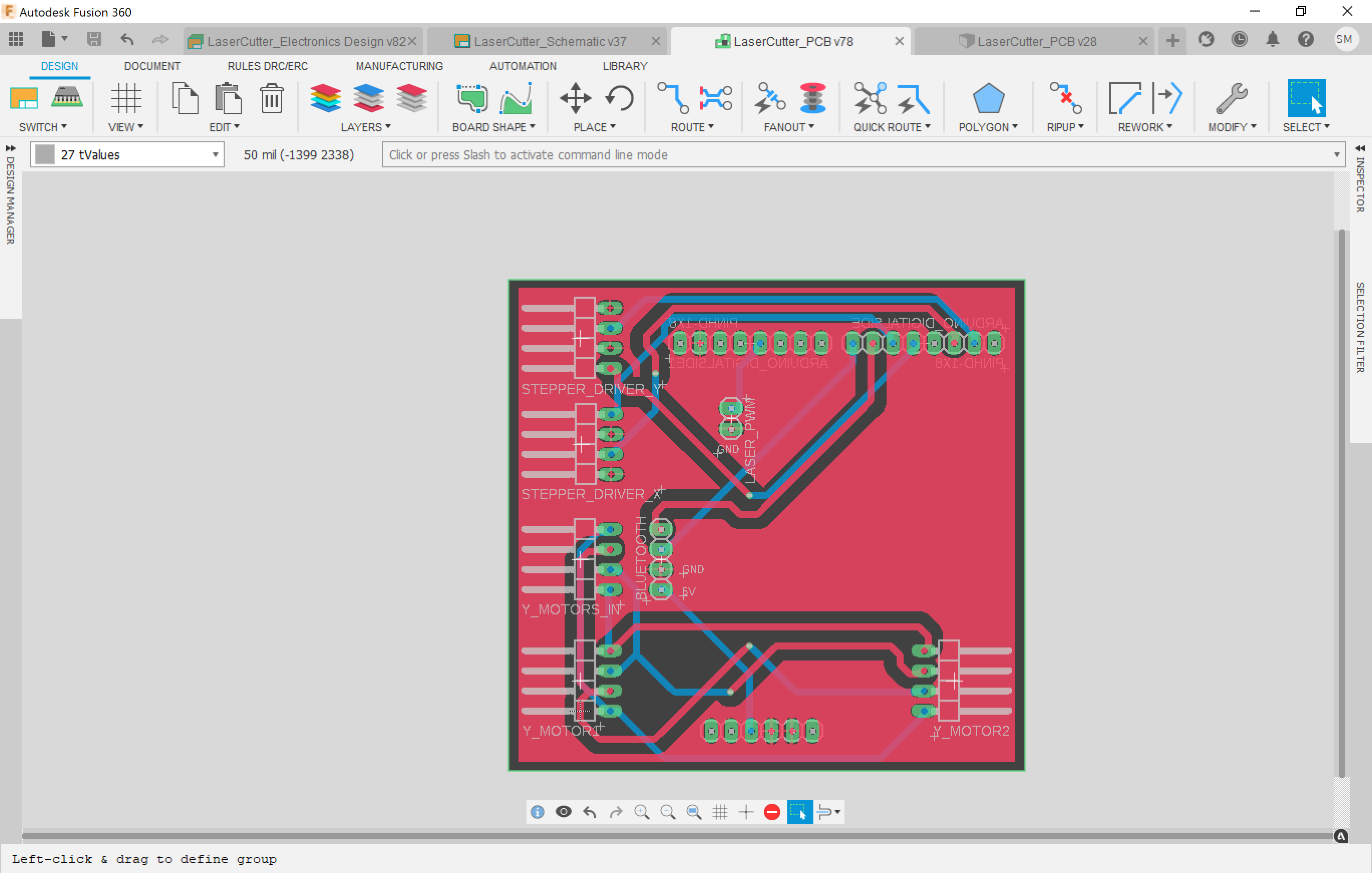
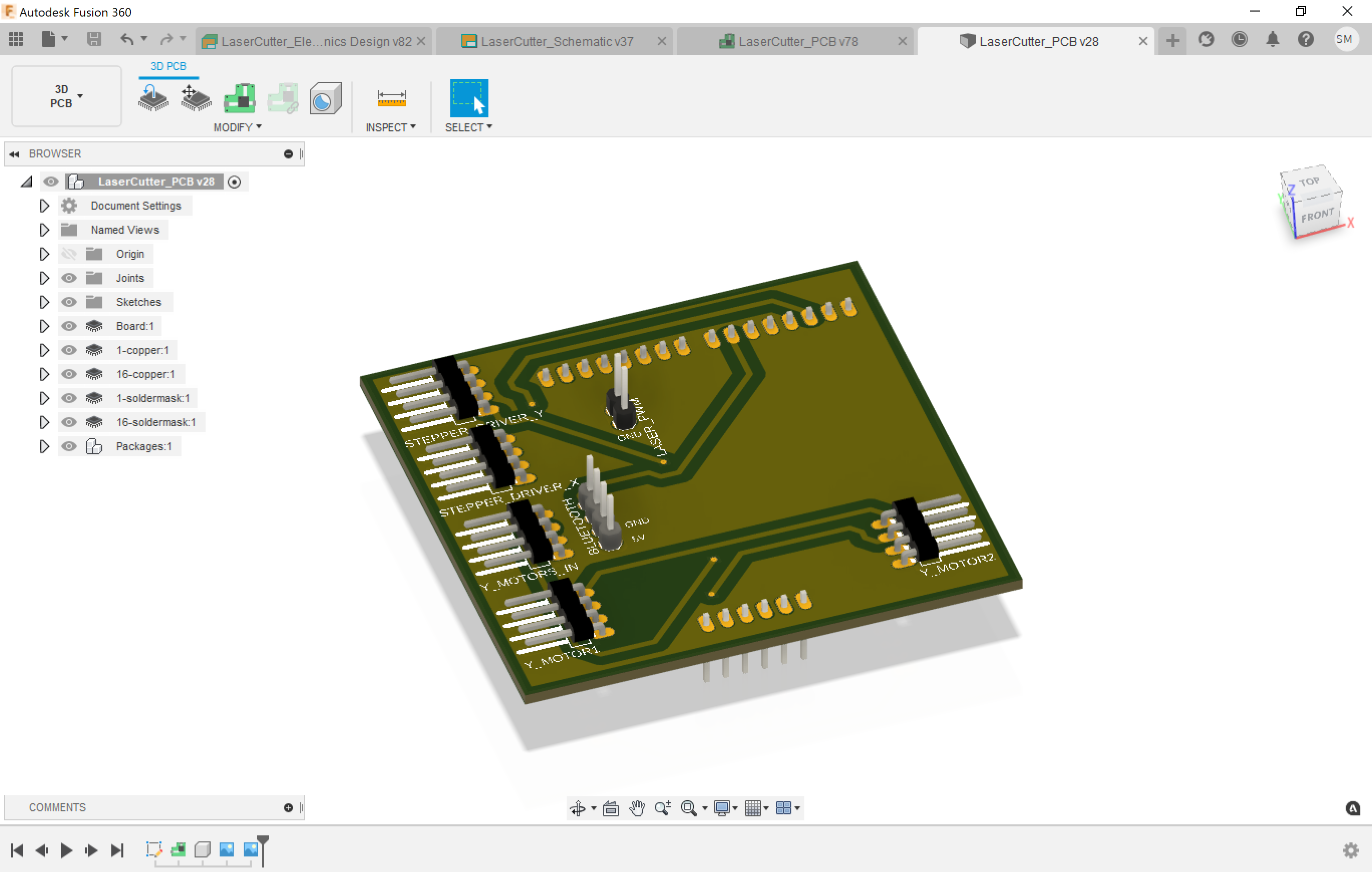
Another awesome use for Autodesk Fusion 360 is designing circuit boards. The design workflow seamlessly flows into your physical project design allowing you to design perfect enclosures.
Our design could use a circuit board that cleans up the all electrical connections. We are driving two stepper motors with one driver, so that will help a bunch.
To create a circuit board in Autodesk Fusion 360, it's easy as one-two-three:
- Add some headers to a schematic and wire them together.
- Position the headers on a 2D Board Layout.
- Switch over to the 3D view to see how it looks and drag it into your main project file so you can design a bracket for it.
Once you are happy with your design, you can then jump to OSHPARK.com to get an affordable PCB manufactured. It makes you awesome!
See the pictures above for reference of the 3 step process. For this build, we simply soldered up to a protoboard.
Creating and Printing Instructions for Yourself
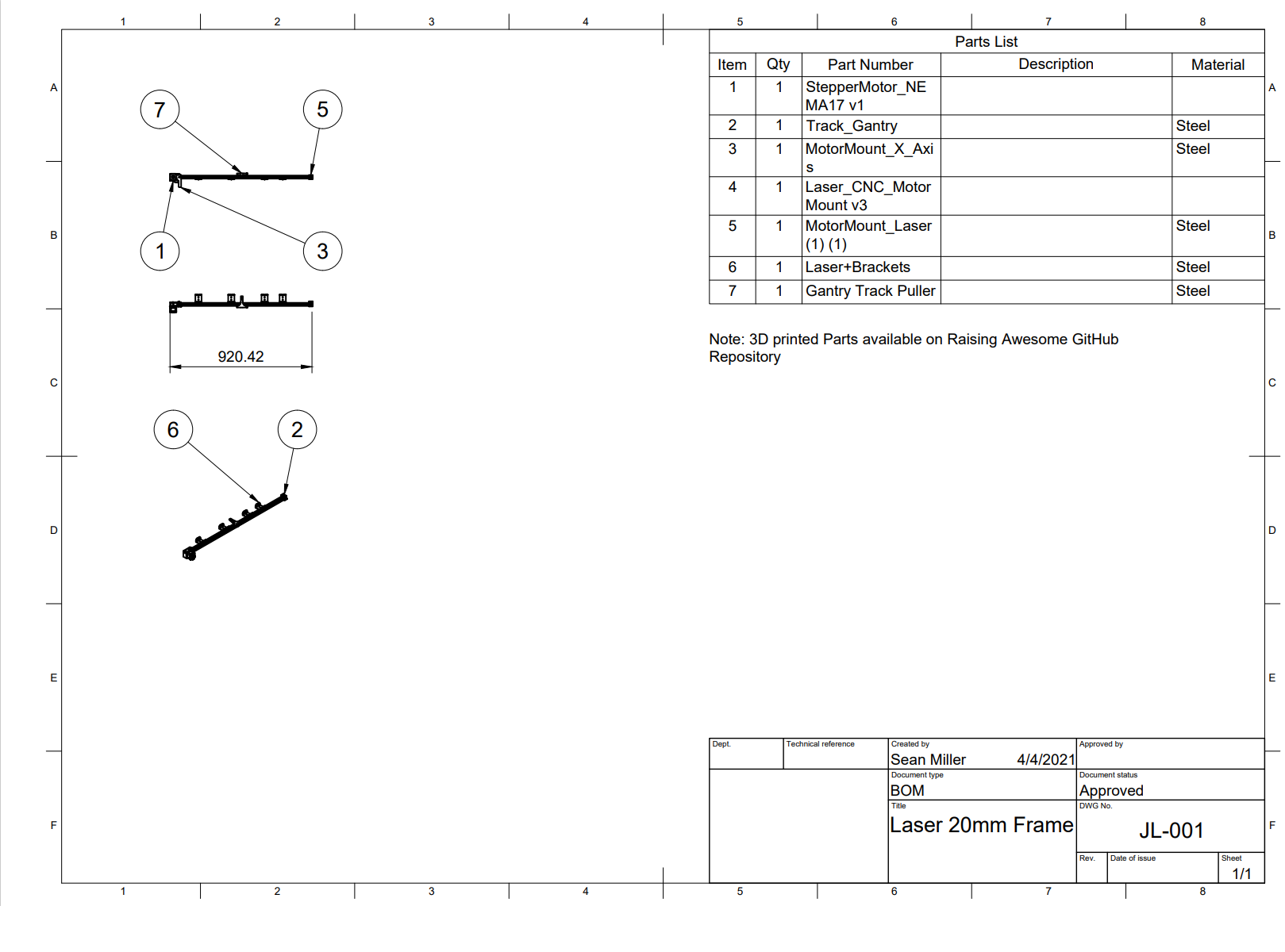
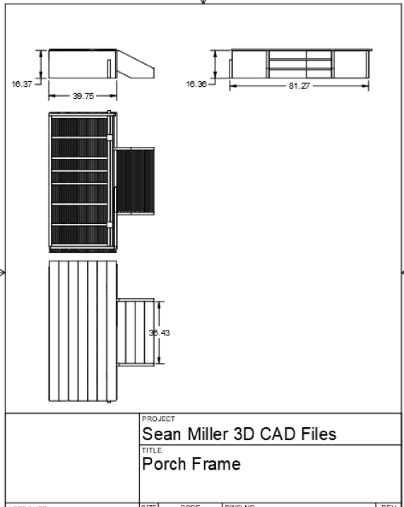
Autodesk Fusion has a great 2D drawing creation toolset. It lets you add drawing details for cutaways, views from all angles, and the bill of materials. It's linked to your design which eliminates the need for you to draw anything for the 2D printout.
To use it, simply click File-->New Drawing-->From Design.
You can then add annotations and different details that will help you assemble. See the picture above for an example.
Wiring the Controls
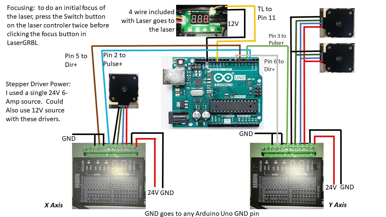
Since the Arduino came on the scene, CNC for the Do-it-Yourselfer has become as easy as one two three: Download LaserGRBL, Flash your Uno, Wire it up.
- Download LaserGRBL:
LaserGRBL is an open source software for controlling an Uno that has the GRBL firmware installed - which is also open source. You can download it here. - Flash your Uno
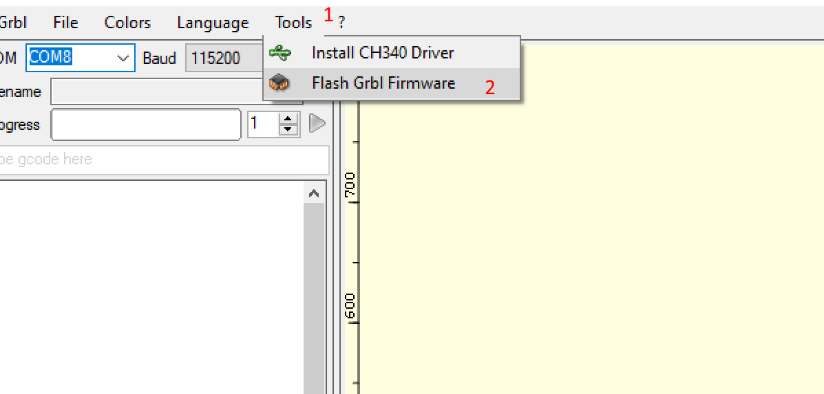
Hook your Uno to your PC with a USB cord. Launch LaserGRBL. Select Flash GRBL Firmware and that's it! - Wire it up
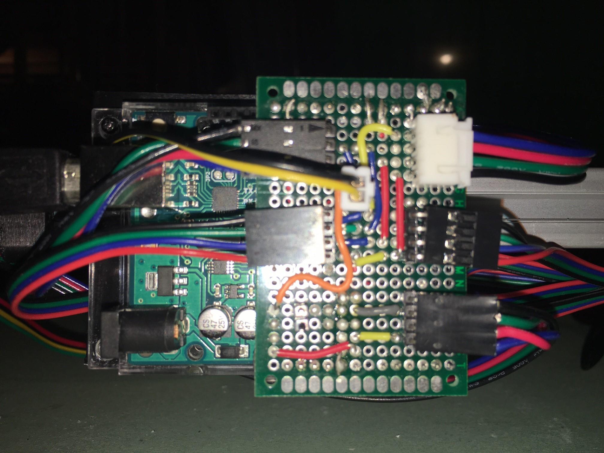
In our design, we are driving two steppers with one driver for the y-axis. This makes for its lightweight design allowing us to use belts instead of a heavy rod to transmit the motion to for the other side. The wiring for this approach is handled in the previous section with the protoboard we made. However, you can just simply omit the board and connect two wires to one terminal for each of the 4 stepper positions.
See the images above for the hookup guide.
Physical Assembly
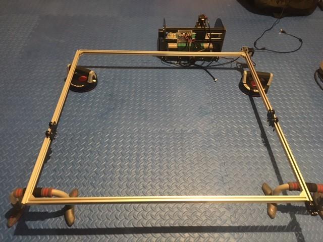
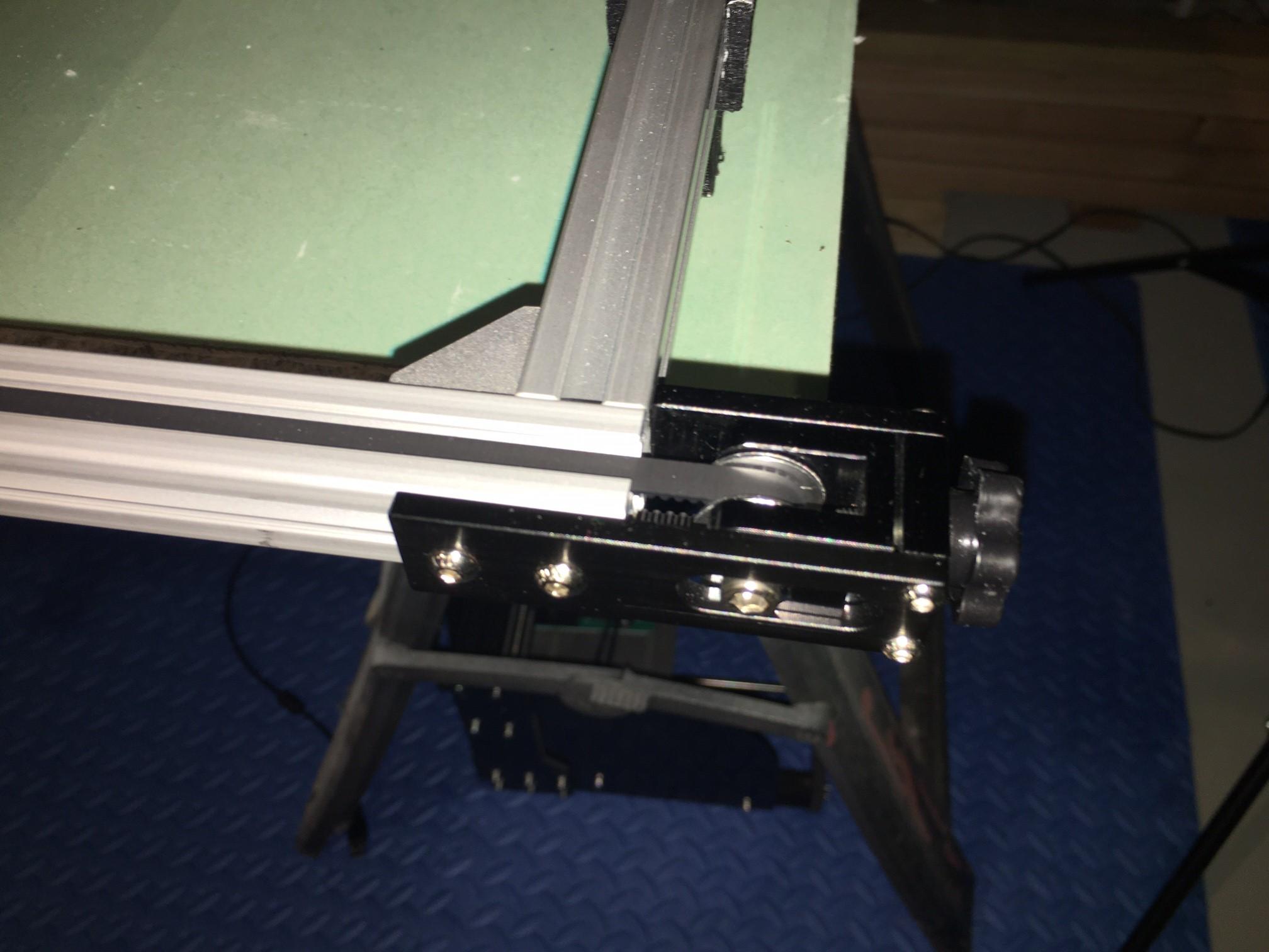
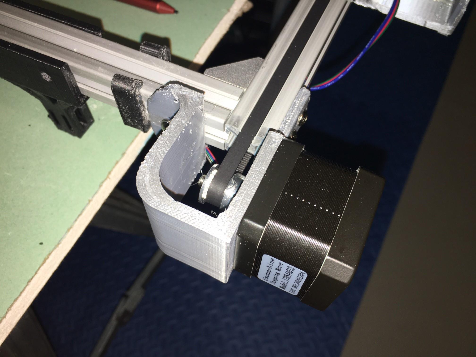
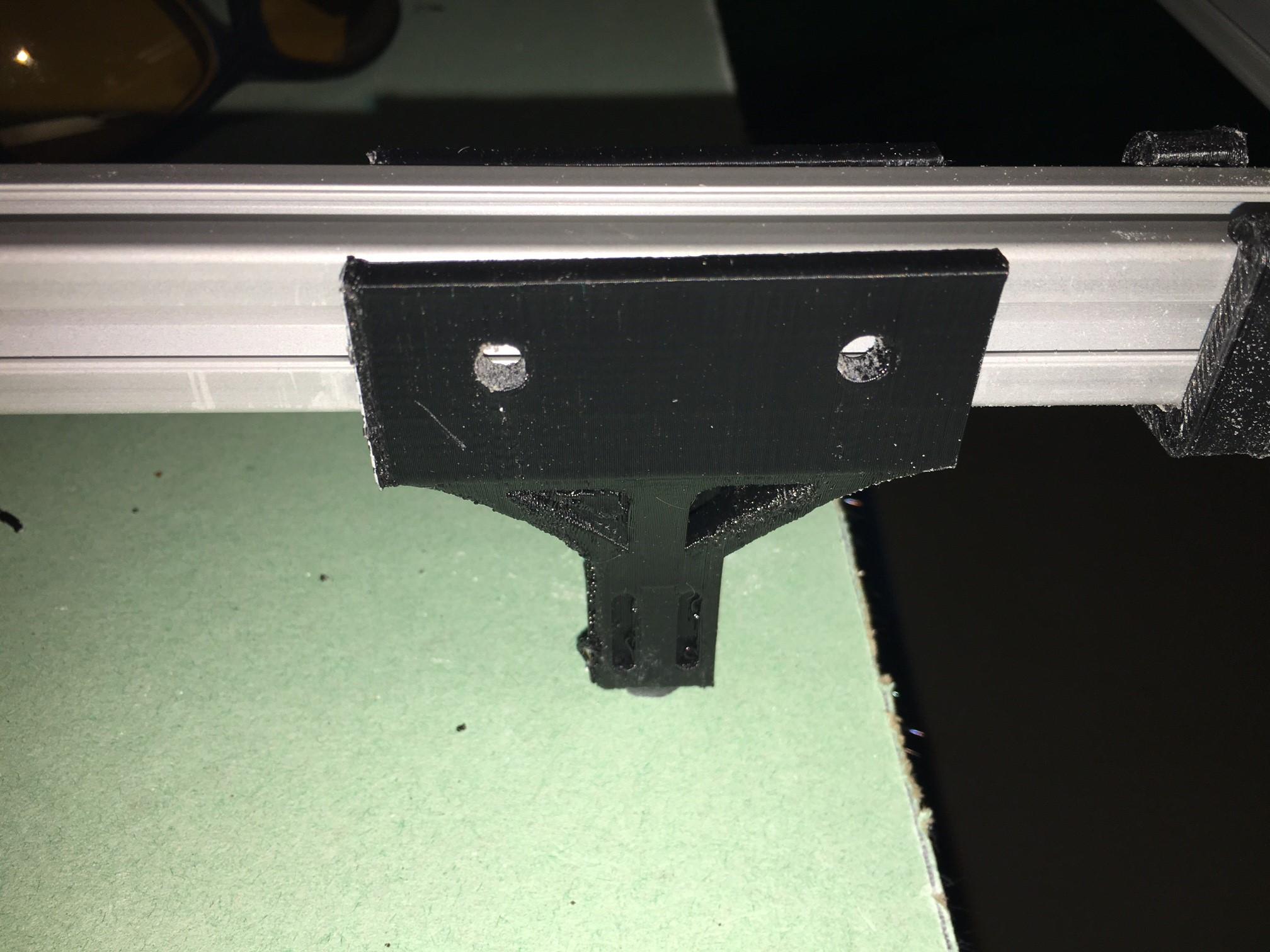
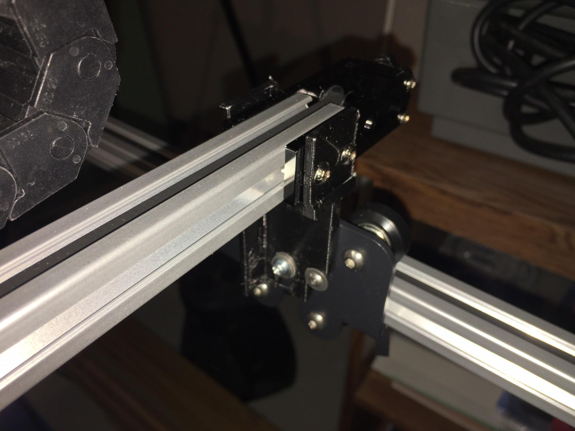
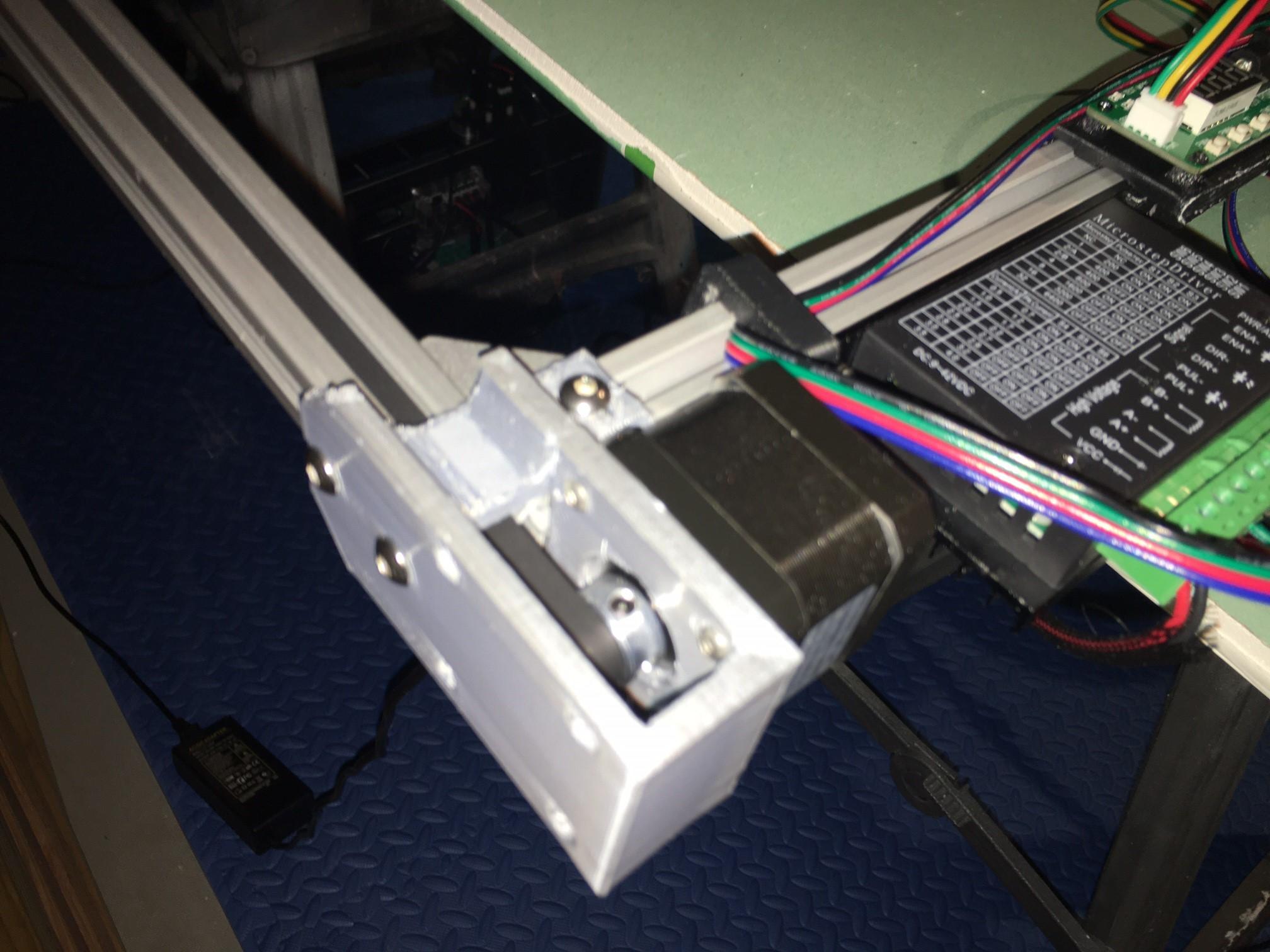
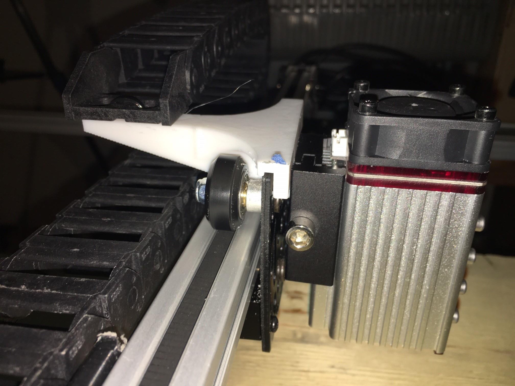
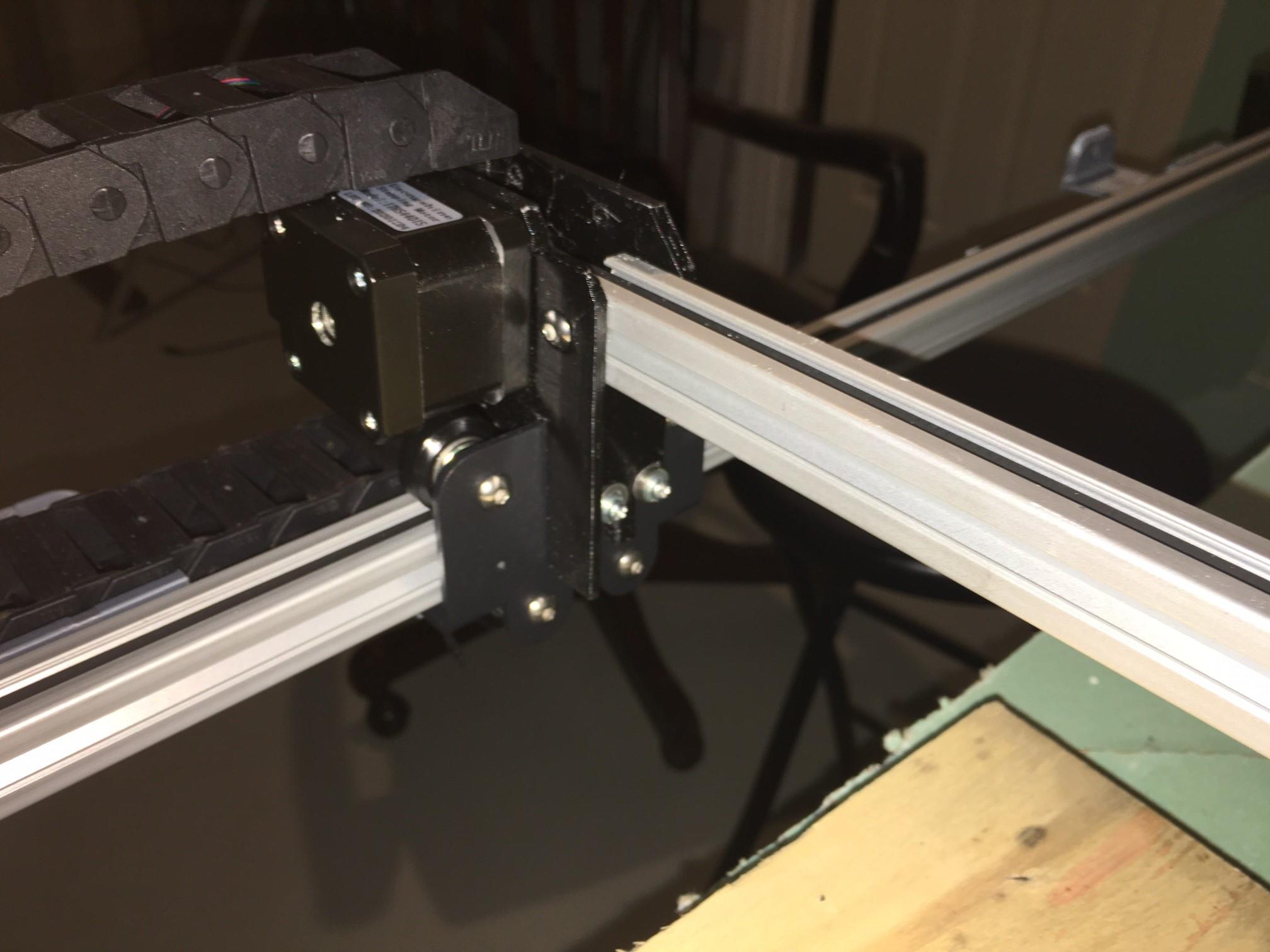
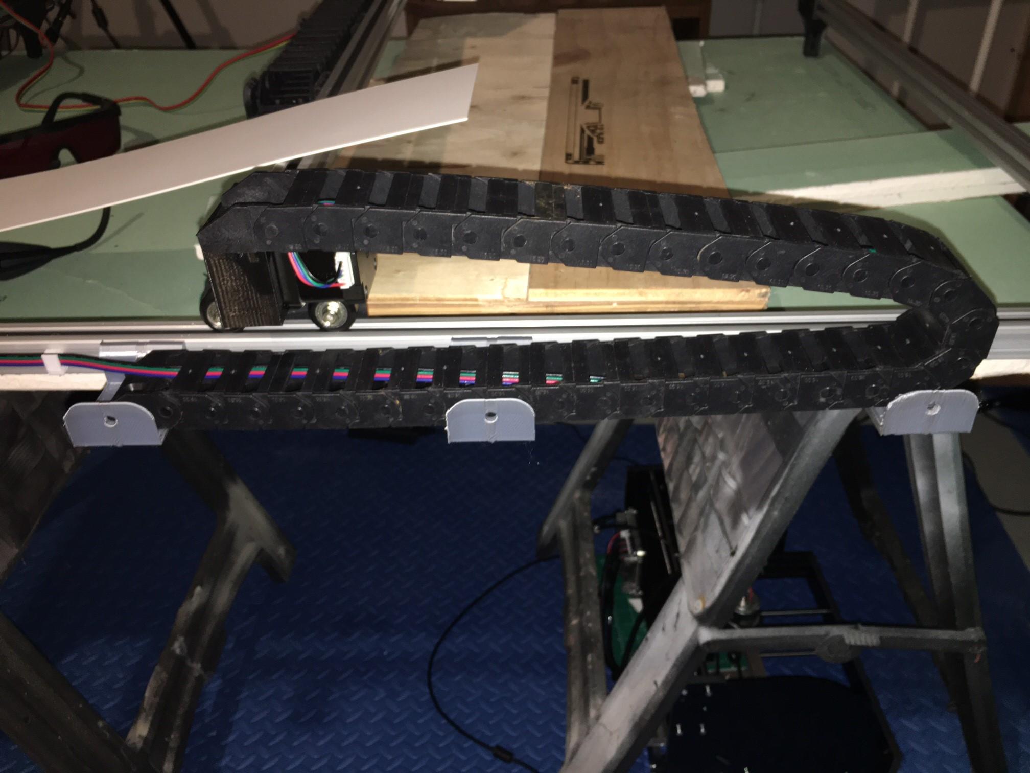
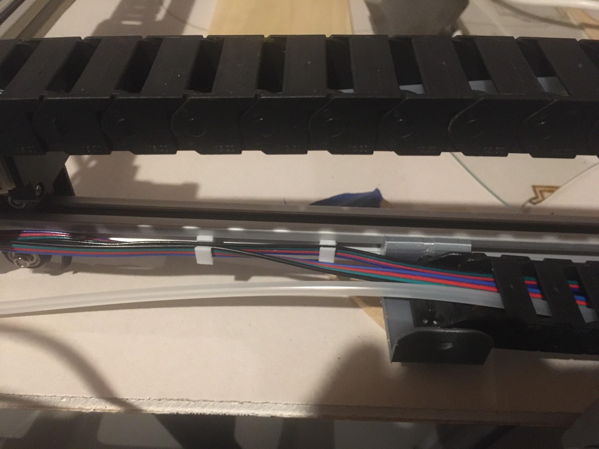
And now for the fun part - Assembly! You just need a couple of Allen wrenches and about one (1) hour of time and you'll have yourself a completed Laser Etcher!!
The first picture above is mine partially assembled as the parts were printing. I did an early test of the steppers by cheating the controls with my CNC 3018 - a DIY CNC engraver. The rest of the pictures simple show the fasteners applied to each component.
The components simply mount using the T-Slot hardware. We found the legs didn't need the fasteners as they were a good snug fit.
One thing with assembly of printed parts, you don't want to tighten and break a part. With variation between parts, printers, and printer slicer software, here are some tips for quick fit up adjustments to save a reprint:
- If your screw is too big for the printed hole, use a drill to step up the hole size.
- If a 3D printed hole doesn't line up with its mate, use a drill to step up the hole size.
- If a hole is bigger than the screw head you are using, add a washer.
- If a tolerance is too tight, use a metal file to take away a little material on the printed part.
- If a tolerance of a joint has a gap bigger than a millimeter, add a shim, spacer, or washer.
For the y axis wheel plates, you need washers for the bottom screws to bind it to the gantry brackets. The design is made to allow the top to be easily slid down into place. In turn, you need screws with washers to catch the bracket.
Adjusting for Perfection
There are three adjustments to make for it to perform perfectly:
- Gantry Alignment:
This is to ensure the left and right y-axes rails are in alignment. Simply take a tape measure to both sides and push the gantry by hand to get them to match.
- Steps per millimeter
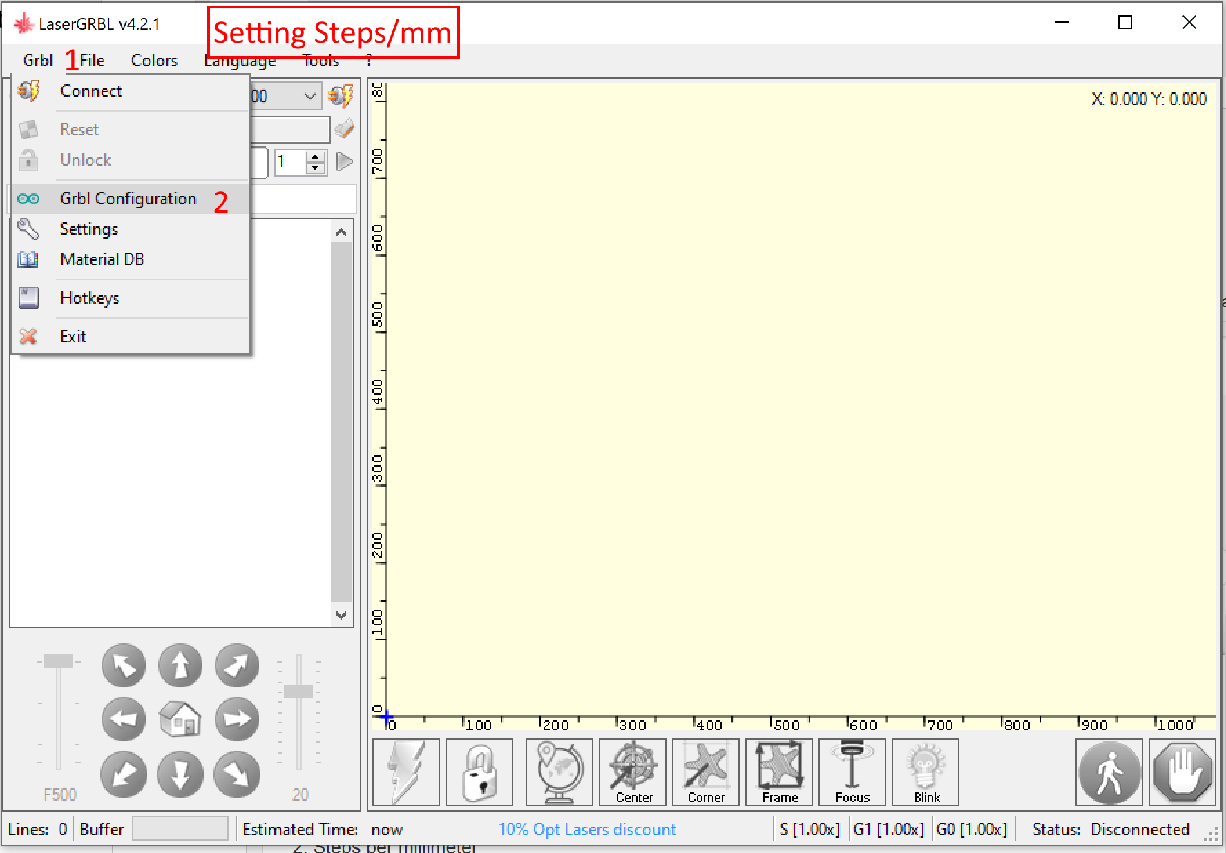
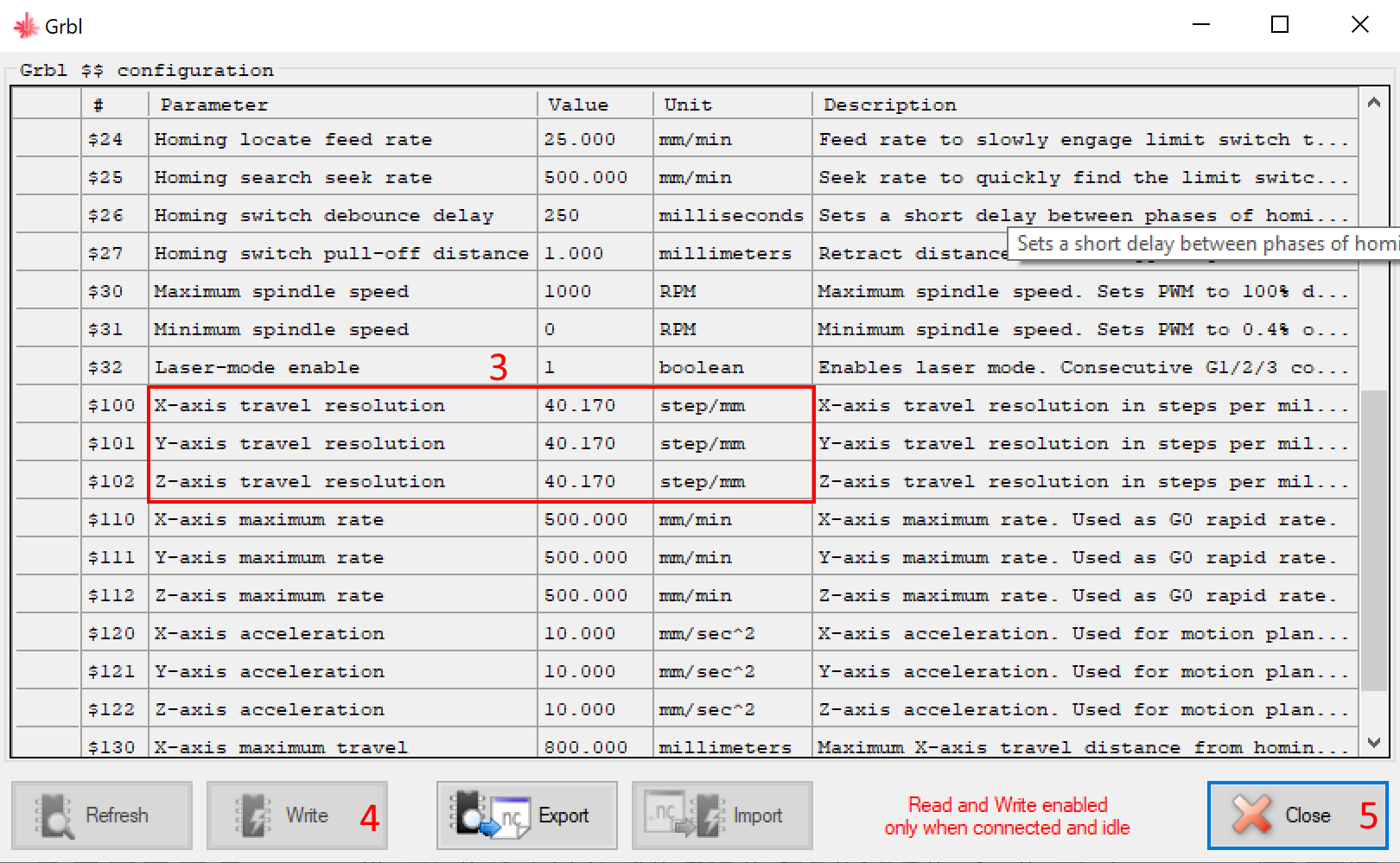
By default, the Arduino's firmware will be 250 steps/mm as installed by LaserGRBL. Since it doesn't know our mechanics, this isn't a match. When you move 10mm, it will move about 6 times that distance. It's pretty cool to watch because its so fast, but it will be too difficult to work with always having to do math each time you use it.
Based on the 5mm pullies with the 2mm timing belt pitch used in this design, the steps/mm needs to be set to 40.170. I actually derived this empirically; that is, I told it to etch a 50mm line, took its true measurement, and then got the fudge factor I needed to apply. To change it in LaserGRBL, click the menu Grbl-->Grbl Configuration as shown in the pictures above.
- Laser Focus
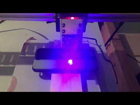
There is a small wheel in the front of the laser that is turned one way or the other to adjust its focus. However, it will be limited by the distance to the object being etched or cut, so you may need to place more scrap material under it. (Never just etch without scrap material under the laser or you'll etch your furniture!).
You'll see my first etch job in the video above where I built elevation with some scrap wood and sheetrock until I got the focus. Last, LaserGRBL has a focus button that turns the laser on low power - this too, you'll want to point at scrap as it still will burn a little mark.
GRBL With Autodesk Fusion 360

I use LaserGRBL as the controlling software for our CNC as it is compatible with the Arduino UNO. I chose it as it is quick for beginners and is very popular. Although it can import images and generate g-code to drive the CNC, you are waaaaayyyy ahead to use Autodesk Fusion 360 to generate your g-code.
This is why I prefer it:
- Using it will expose and educate you on everything possible in the world of CNC (laser, milling, plasma, etc) - it does this with popup help that has pictures and definitions for everything!
- You get clean, precise paths for etching and cutting. No more sloppy imported jpeg approximations.
- You can chain etching and cutting operations in one program
- You can simulate the process to ensure nothing will physically go wrong
- If you had multiple heads, you could pause and switch to milling
- You can autogenerate some instructions for your CNC operator
- Your physical project can encompass all aspects of the design and fabrication in one file
The above video walks you through the workflow to generate G-Code for your new laser etcher. Follow along with the following in Autodesk Fusion 360:
- Open a new file and create a sketch
- Add some Text.
- Click the Manufacture Workspace button
- Click the Fabrication menu item.
- Select Cutting.
- Set your tool to Laser and select Etching.
- Select the profiles to etch.
- For fun, simulate the process with Actions -->Simulate
- Click Actions-->Post Process to generate your G-Code
- Open LaserGRBL and choose File-->Open and you are ready to etch!
Optional Upgrades
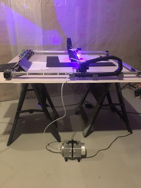
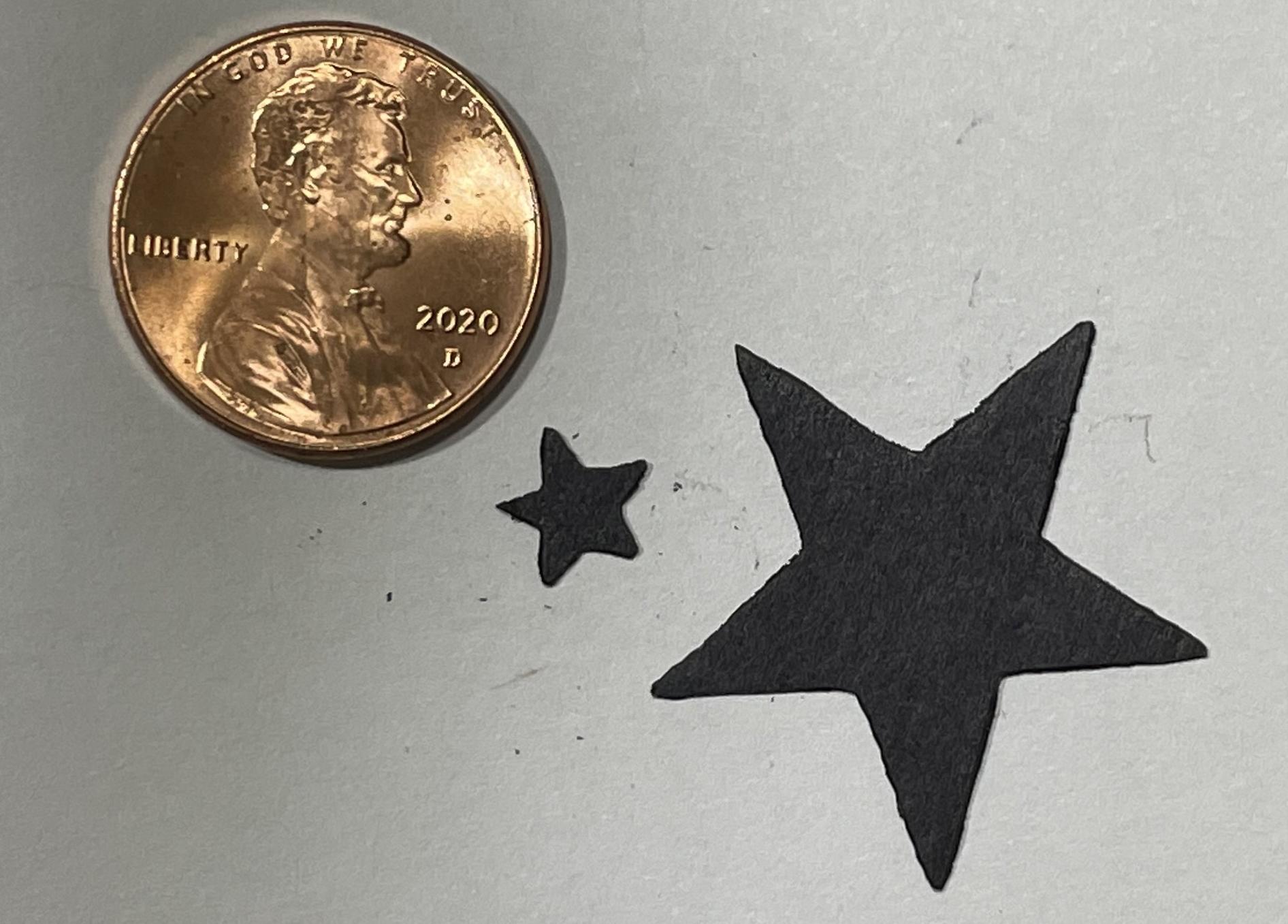
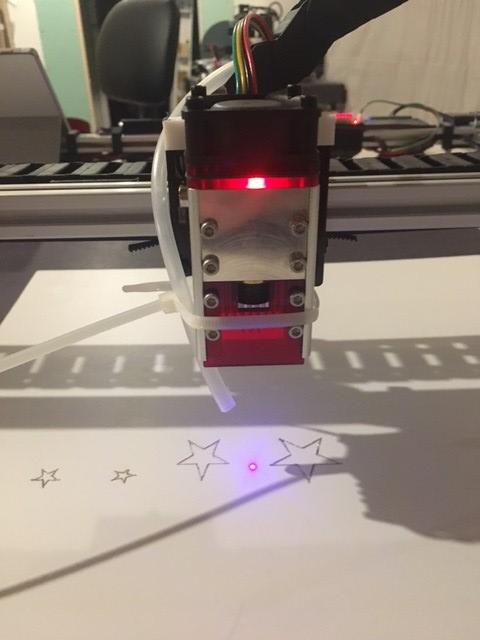
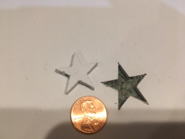
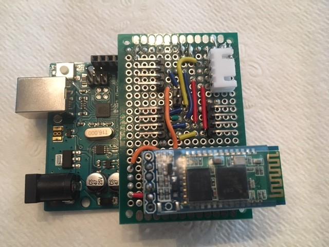
Air Pump:
The major upgrade to the quality of cuts is an air pump:
I simply ran 3/16 ID tubing through the cable track and zip tied it to the laser..
The results were great particularly for materials that can catch fire easily such as poster board. I was able to cut poster board on 100% in one pass with great results. Without the air blowing at the laser point, I caught the poster board on fire! Prompted my wife to by a can of suppressant:
First Alert AF400 Tundra Fire Extinguishing Aerosol Spray - Fire Extinguisher Can - Amazon.com
It also did well to reduce melted edges when cutting through 3mm High Impact Polystyrene as shown in the pictures above.
Bluetooth:
It got old hovering close to the laser with my computer, so I added a Bluetooth module to the circuit. See the picture above.
IP Camera:
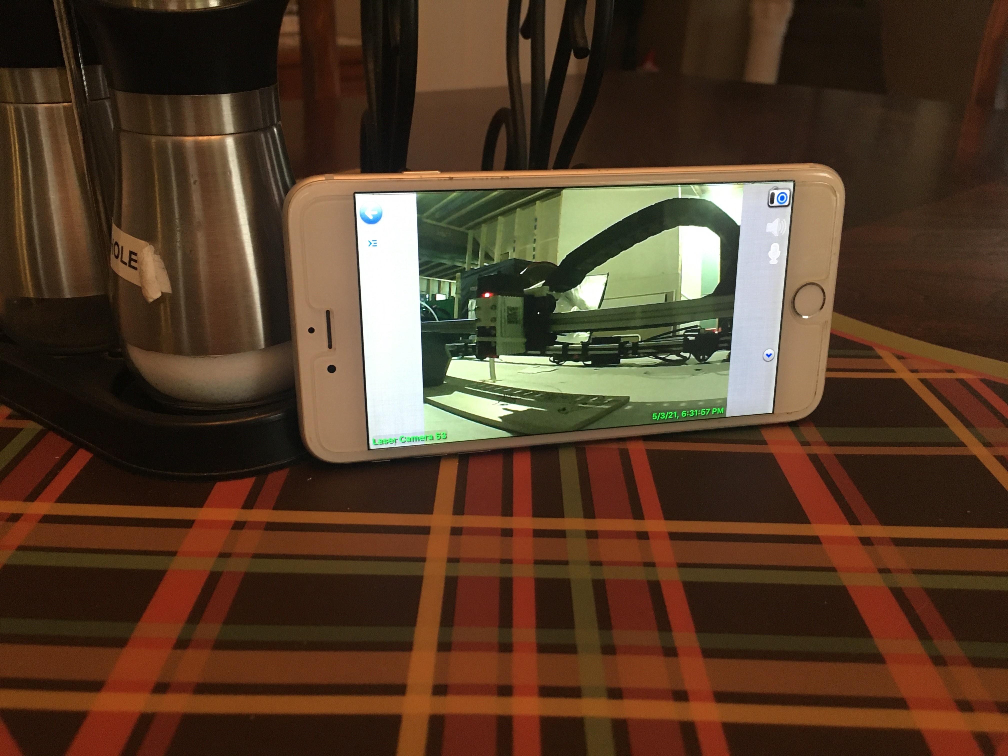
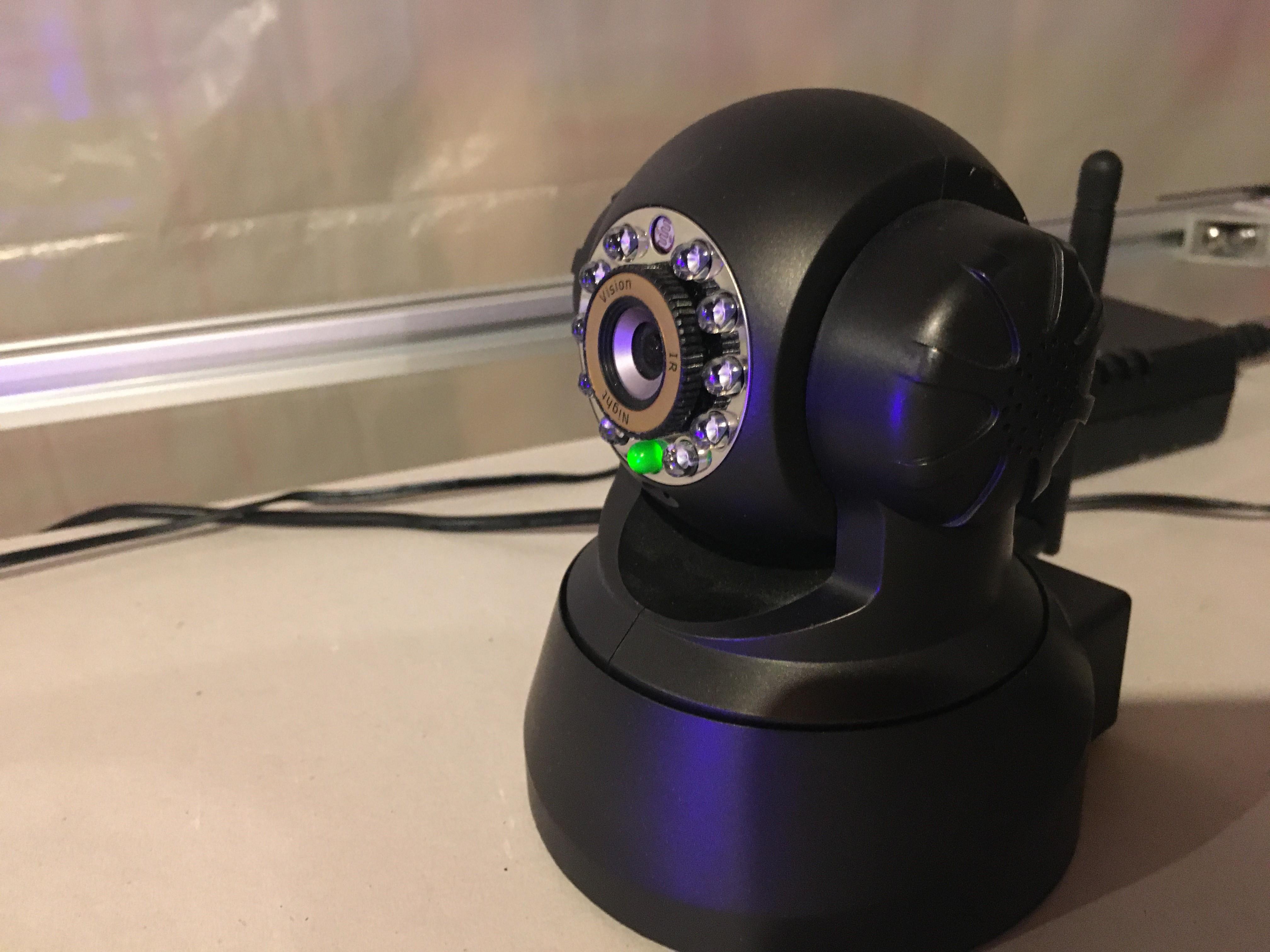
Deep engraving with a few passes can take at least a half hour. To stay productive, an IP Camera can set you free. Sure, you could even mount a camera to the laser, but I like simply setting the IP Camera that I can "look around" the machine while it's running. These are cheap on eBay. Also, it's a good use of an old iPhone that's just been sitting in a cupboard from two upgrades back. See the pictures of it above.
Limit Switches:
Another great add on, particularly if you are new to LaserGRBL, is limit switches. The GRBL firmware already is ready for them. You just run the wire from the corresponding GRBL limit switch pin back to ground. When the pin pulls low, it will immediately stop. Saves you have to pull the cord in a panic - but that works too. Shout out to wrbonomo for his design and pics in the comments!
Conclusion

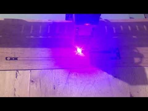
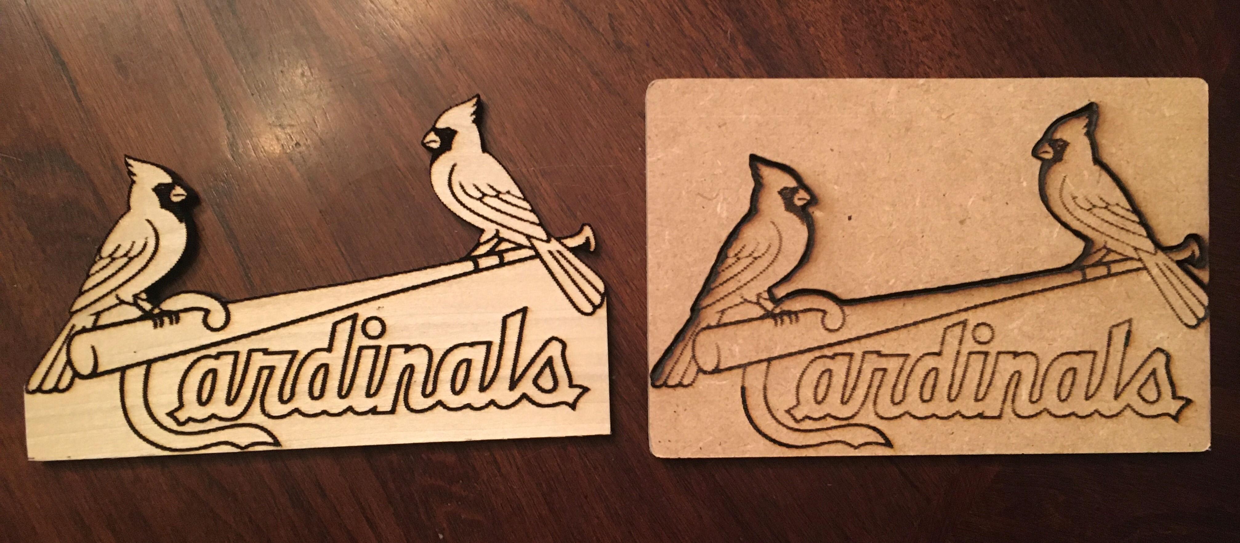
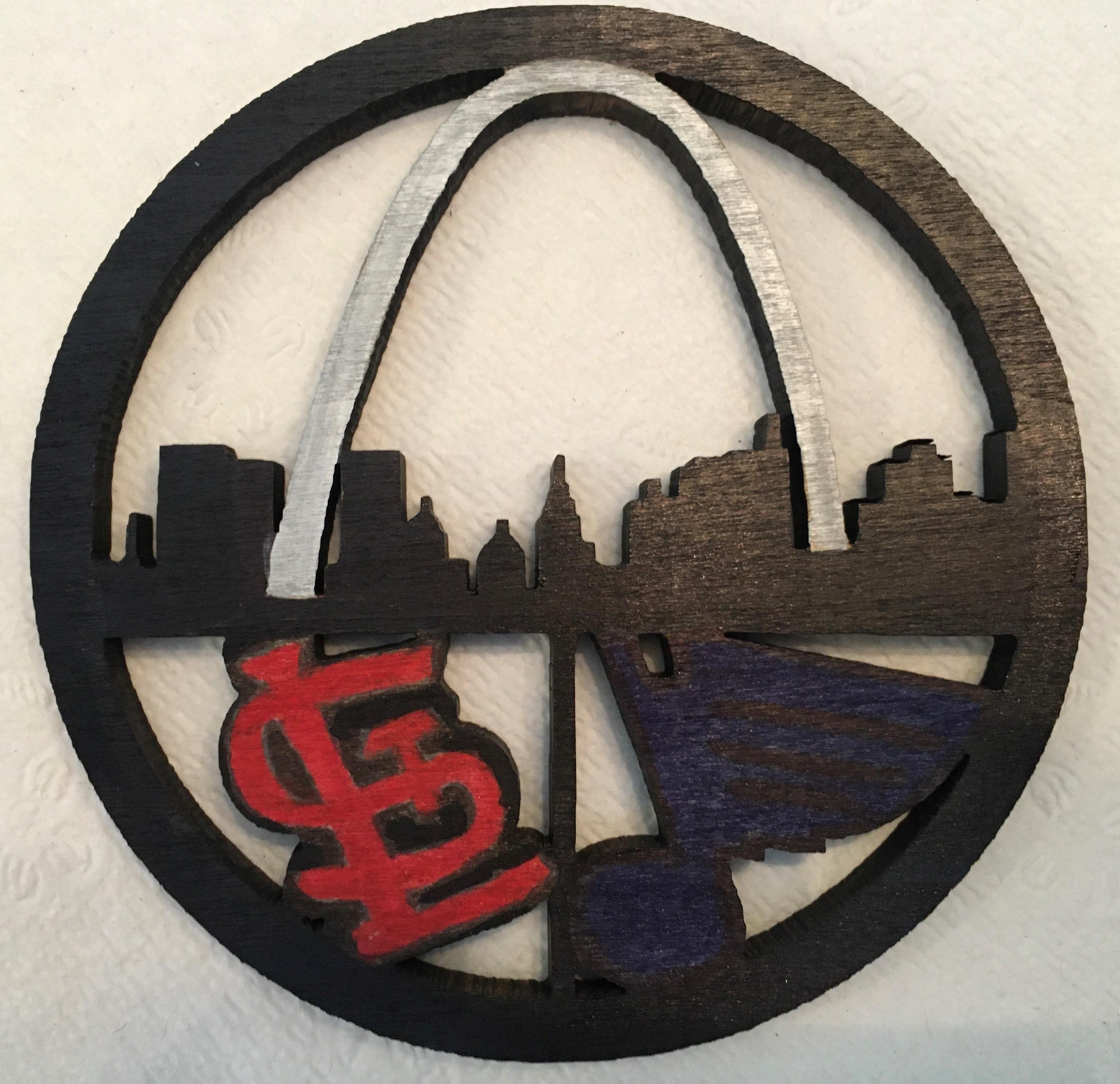
If you are new to the maker community, this project may seem out of reach. However, if you complete it, you will reflect that it really is simpler to assemble than a Lego kit. However, the skills you will pick up with Autodesk Fusion 360 will have you ready to make the most advanced mechatronics projects you can imagine.
If you have any questions, please comment below and we'll quickly get back to you.
Visit us at Raising Awesome on Youtube for other maker projects.
-Sean and Connor Miller
Our Projects: http://www.raisingawesome.site