January 2014 Build Night With CoolNeon Part II - Parking Proximity Indicator
by h3-JG in Circuits > Wearables
4314 Views, 24 Favorites, 0 Comments
January 2014 Build Night With CoolNeon Part II - Parking Proximity Indicator
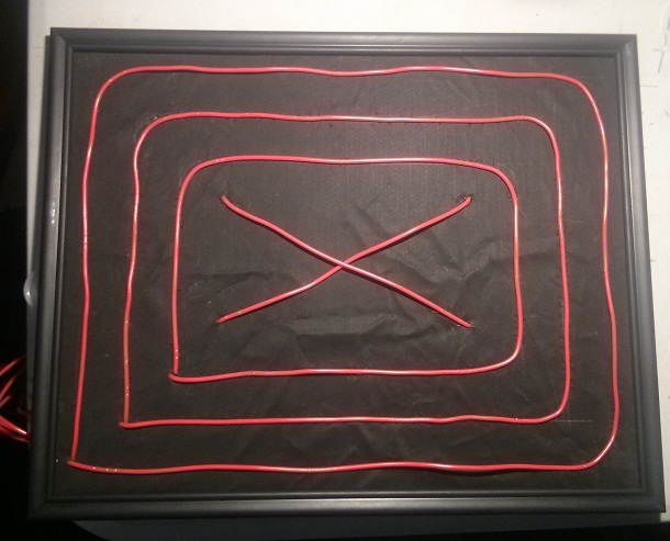
Ever have trouble parking in your garage? Do you hit the back wall or stop too far back to close the garage door? In this instructable we'll be building a parking proximity indicator using EL wire and CoolNeon's EL Wire shield.
We use an ultrasonic sensor to detect a vehicle approaching. As the vehicle gets closer, the lights on the indicator will light up in sequence. A red X will light up at the center when the perfect distance is reached.
Step 1: Materials & Tools
Materials:
- 1 - Arduino Uno
- 1 - CoolNeon EL Wire Shield
- EL Wire (Amount needed will vary depending on your design)
- 1 Ultrasonic proximity sensor
- Fishing line
- Picture frame
- Wire
Tools:
- Sewing needle
- Wire cutters
- Ruler
- Pencil
Step 2: Make the Display
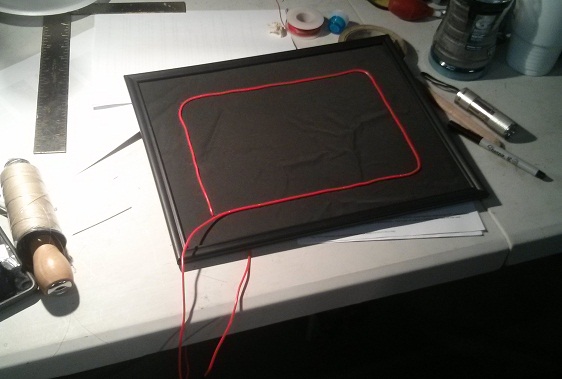
We decided to arrange our EL wire in a series of concentric rectangles with an X in the middle. Feel free to arrange the design any way you want. You can make arrows, bars, letters. Use your imagination.
The display is mounted in a 10 x 14 inch dollar store picture frame with some nylon cloth glued to the cardboard backing. You can use a bigger frame if you'd like or you can even use the back wall of your garage if you want.
We attached the EL wire to our frame by sewing it to the cardboard backing. If you're using a hard backing you can use staples or glue to attach the wire. Make sure to leave extra slack at the connector end to plug in the electronics.
Step 3: Electronics
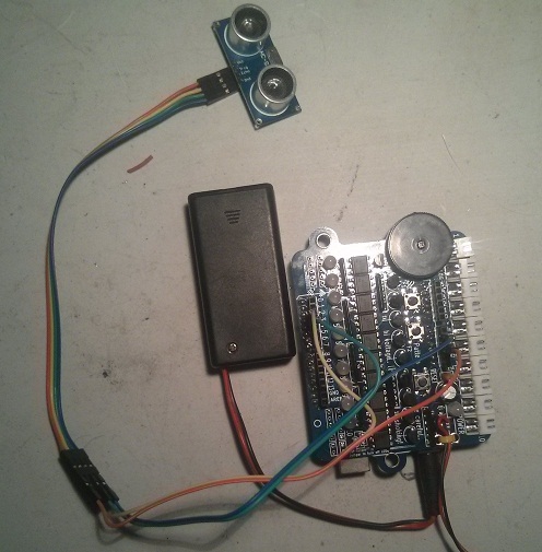
In this step we'll wire the whole thing together.
Prepare the Arduino and shield
- Plug the CoolNeon shield into your Arduino.
- Plug the EL Inverter into the shield
Connect the EL Wire
Plug the EL wire ends into the CoolNeon shield. The light sequence starts at one and goes up with the light sequence.
Proximity Sensor
Some ultrasonic proximity sensors use 3 pins others have 4 pins. Ours is a 4 pin style. Don't worry if your sensor has three pins. We'll explain how to wire both styles.
- Wire the +5V pin to +5V on your Arduino
- Wire the GND pin to GND on your Arduino
- For 3 wire sensors, connect the Signal pin to pin 2 on the Arduino
- For 4 wire sensors, connect the Trigger pin to pin 2 and the Echo pin top pin 3 on the Arduino
Step 4: Arduino Sketch
Load this sketch onto your Arduino. If you're using a 3 pin ultrasonic sensor, go to line 7 and change the value of the EchoPin constant to 2.
Downloads
Step 5: Mounting
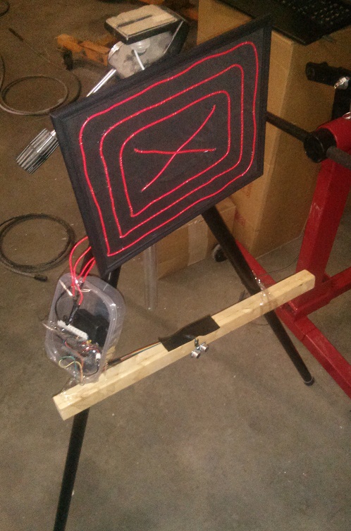
Mount your display where you can see it clearly from your vehicle.
Place your proximity sensor at bumper level with your vehicle. The sketch is configured to light the final wire when the vehicle is eighteen inches from the sensor.
For demonstration purposes, we mounted our display on a tripod with a piece of wood to hold the sensor. The electronics are housed in a food container taped to one of the legs.
Step 6: Testing
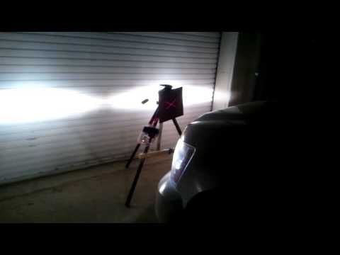
Test the proximity sensor with something other than a vehicle. We approached the sensor with a piece of cardboard.
Test with your vehicle. Make sure you have an observer to check the distance as you approach the sensor.