DIY JAAR - Just Another Autonomous Robot
by sghosh21 in Circuits > Microcontrollers
7827 Views, 33 Favorites, 0 Comments
DIY JAAR - Just Another Autonomous Robot
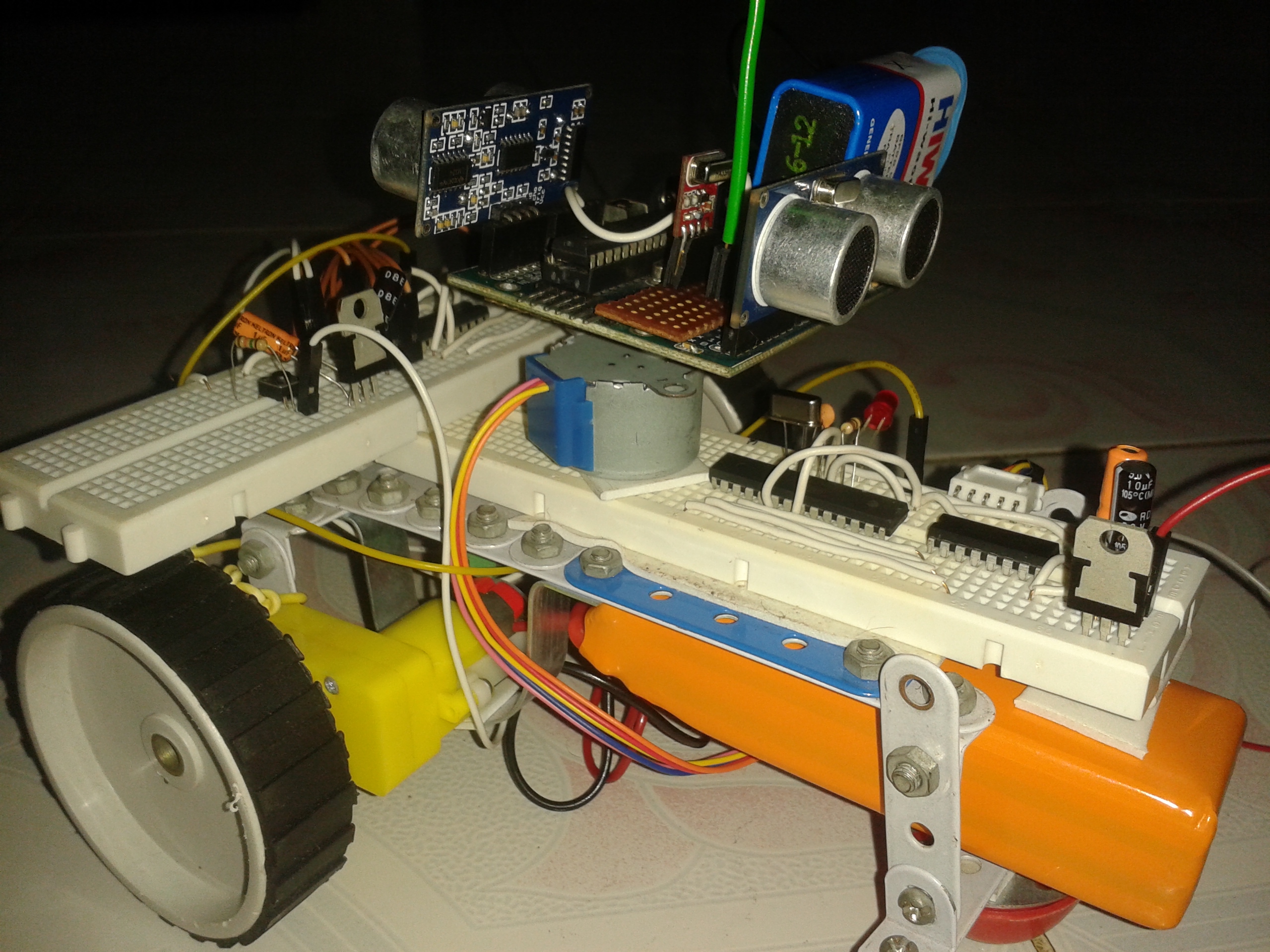
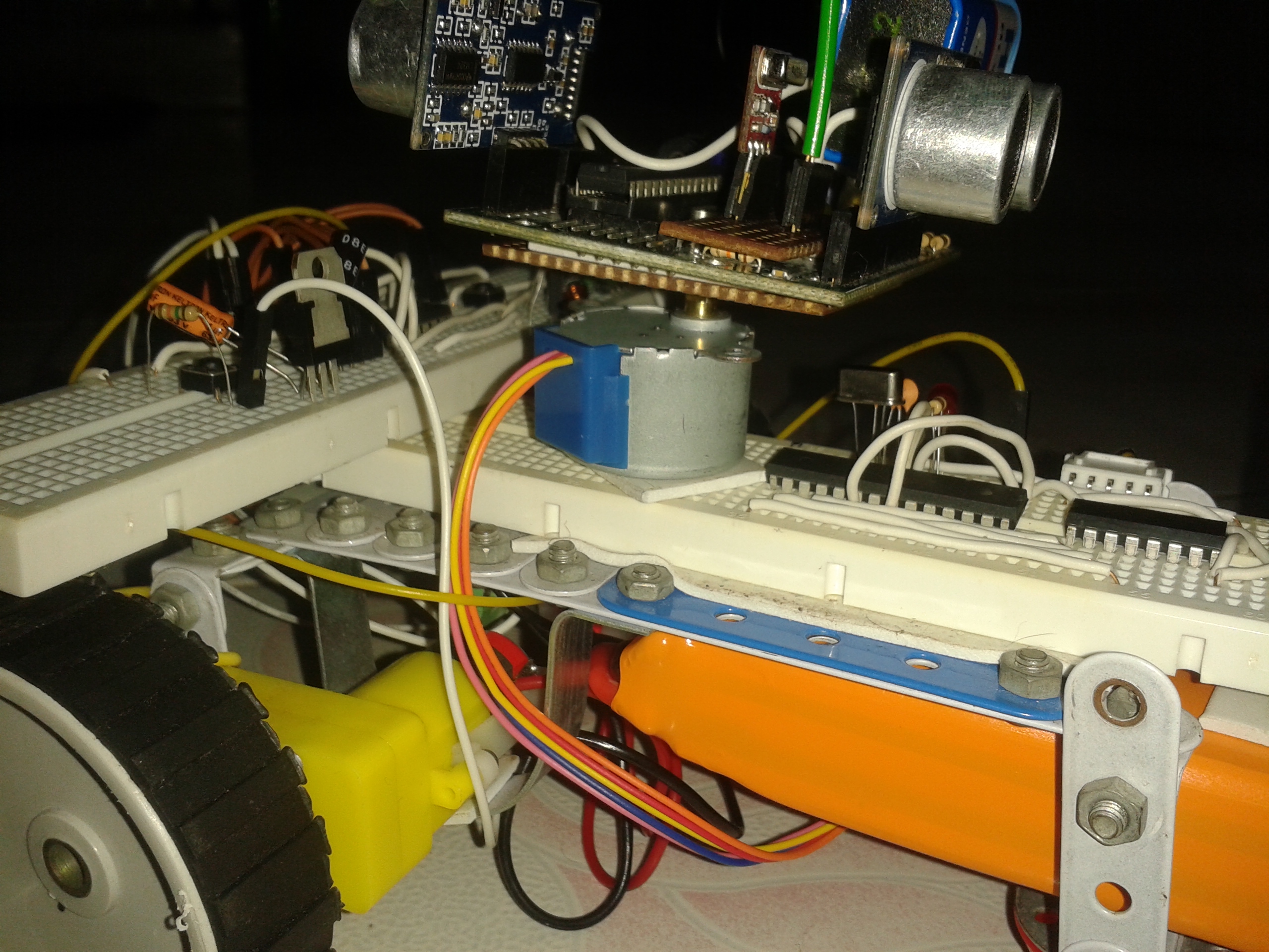
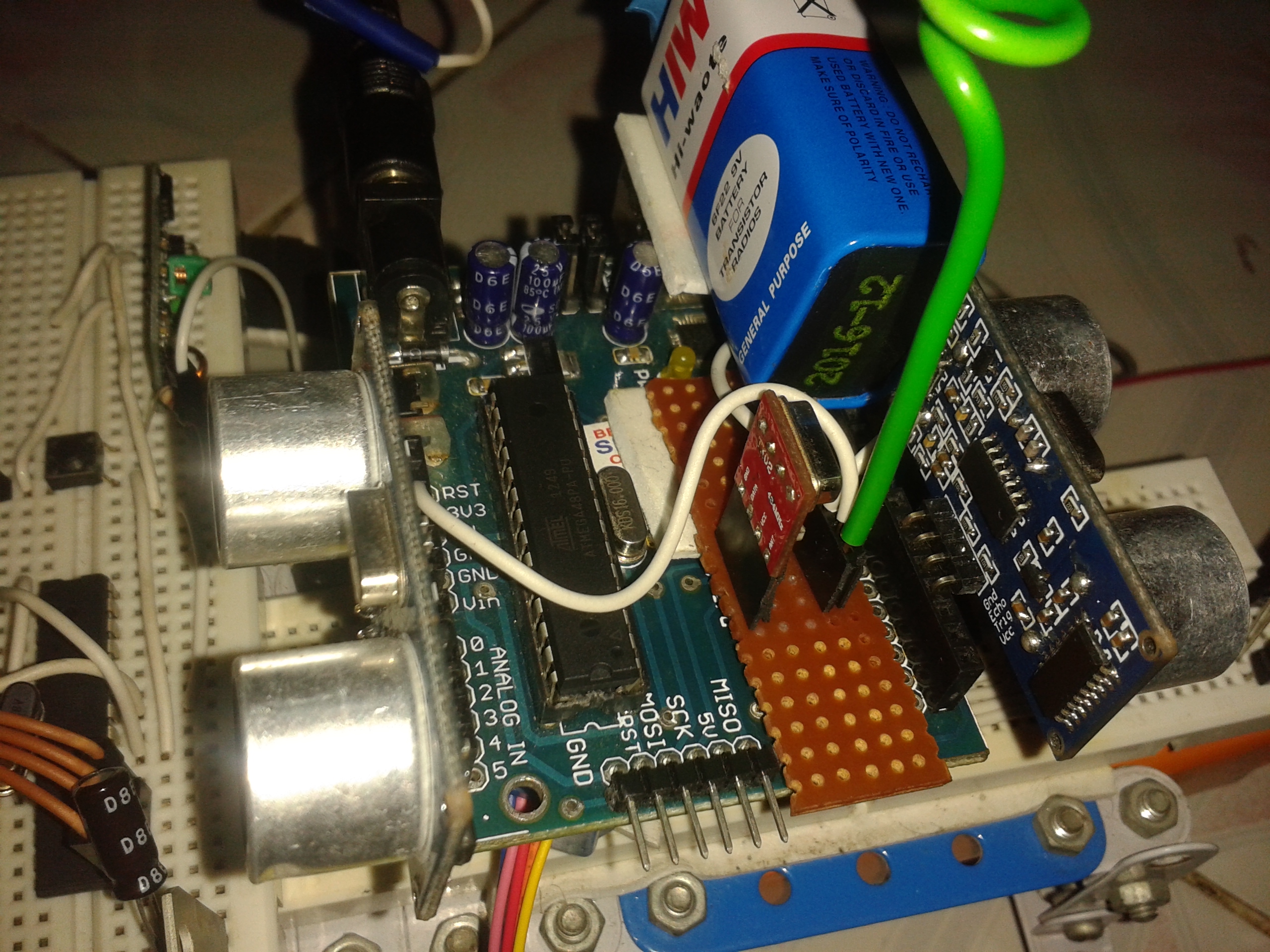
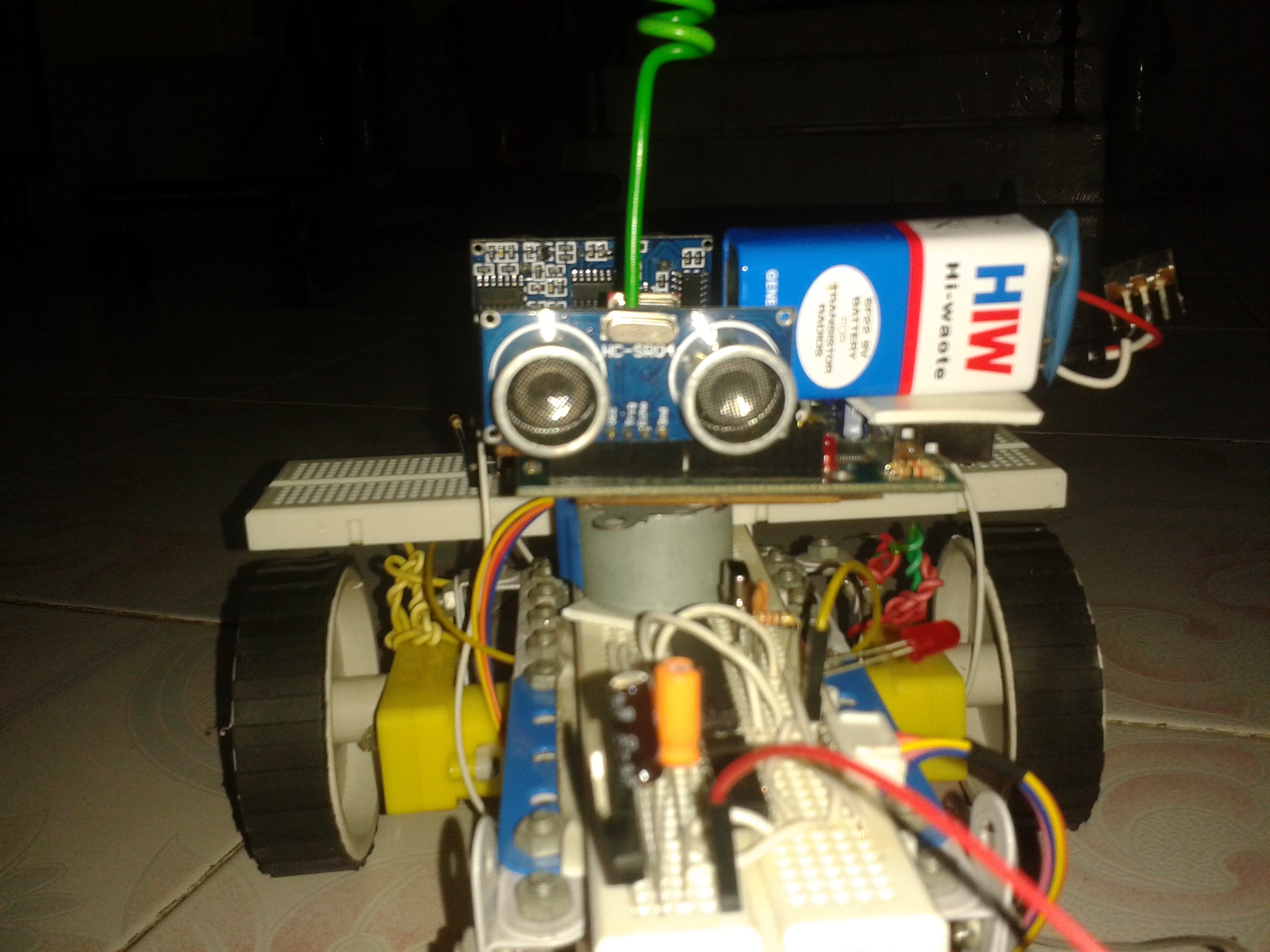
JAAR's concept is not just about making a Rover ....blindly as i tell you to and fool around........its more than just making a Robot........i have incorporated most of my learning from the past 6 months to this project.........seriously speaking i am just a beginner trying to teach another beginner something useful through a cool project .......My first project with Arduino was an obstacle Avoiding Robot , but that rover was quite dumb in many ways, so i decided to improve its concept and tried to map the whole surrounding instead of just some selected parts , thats how i ended up with JAAR.......i checked out many instructables but didn't see my concept any where so thought of making my first instructable ever so viewers plzz help me improve
AIM :- The primary motive of this instructable is to bring up a new concept and starting to do it from some simple and basic experiments and finally completing the robot.
This tutorial has detailed instructions about every small element present in JAAR, so guys and gals plzz be patient coz its lengthy.......!
Concepts which are taught through this Project :-
1. Switch Debouncing (Software)
2. How to measure run time of a program and use it as an advantage.
3. Proximity Sensor Controlling (HC-SR04)
4. Stepper Motor Control (28BYJ-48 – 5V) with a Darlington Transistor Array (ULN2003)
5. DC Motor Control using a Motor Driver (L293D)
6. Wireless Communication between two Atmegas (434 MHz cheap RX and TX modules)
7 .Making an Atmega Standalone
8. Serial communication between two Standalone Atmegas
9. Synchronizing 3 Atmegas to run the robot (Divide and Rule)
10.Programming the Atmegas using the Arduino IDE and an Arduino development board (primary objective) . Without which all the above mentioned concepts are meaningless.
Note 1 : - This instructable assumes that the reader has very nominal experience with the Arduino IDE
Note 2 : - Viewers Suggestions are Mandatory (Plzz comment what you think about this Instructable)
Switch Debouncing (Software)
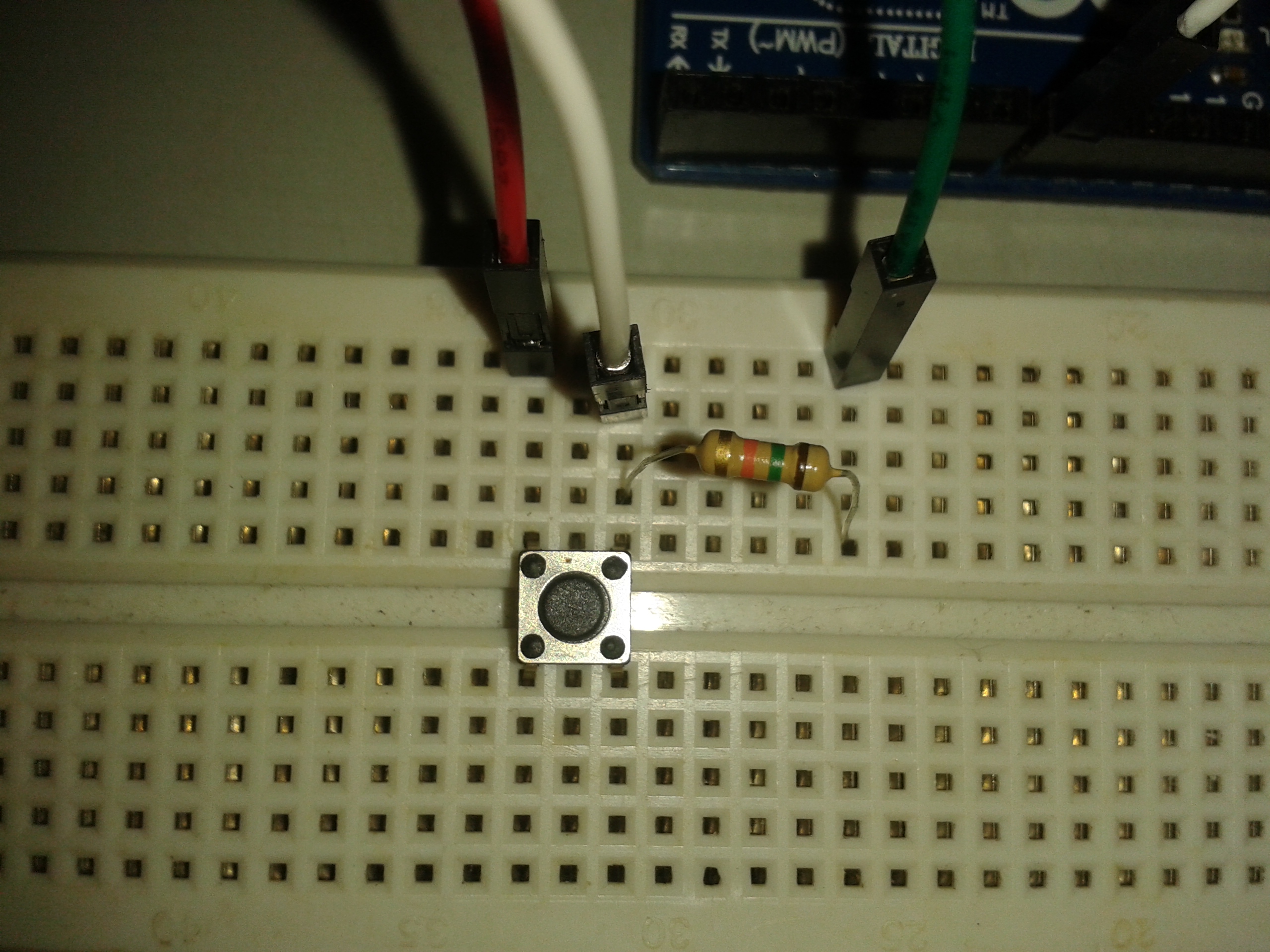
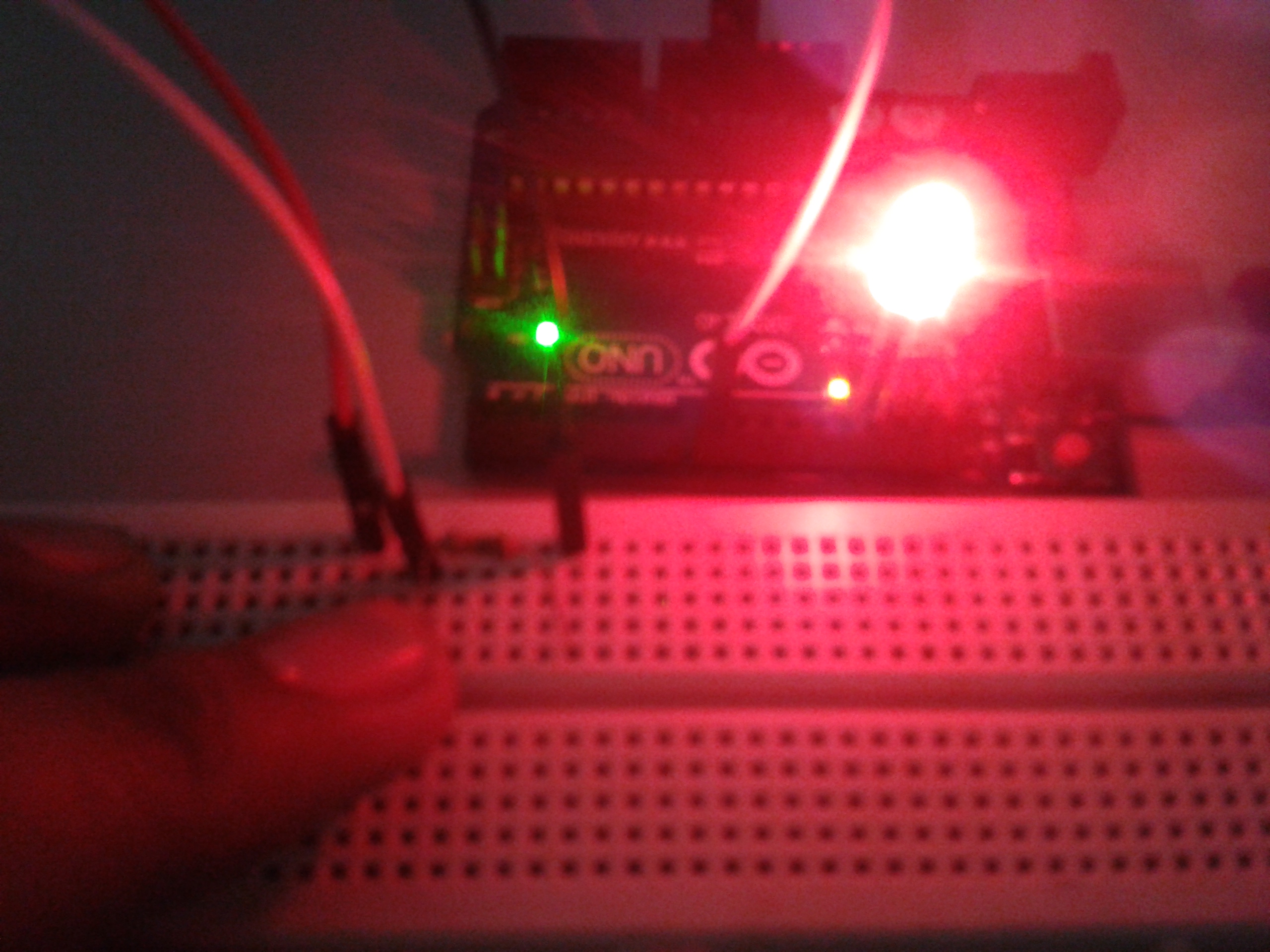
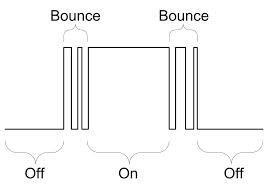
First, we need to know why debouncing a switch is required . So we need to do a simple test of how not to debounce a switch
Objective 1 :- To switch on the Led when the button is pushed switch it off when pushed again
Things required :-
- 1X Push Button
- 1XAny resistor above 1k ohm (resistor required to avoid the electrical noise)
- 1XRed Led (for better visual)
- 1XBreadBoard
- 3XMale to Male Jumper Wire (Common wire should also do fine)
- Arduino Uno or whatever you have at hand
- And obviously a power source for the Arduino
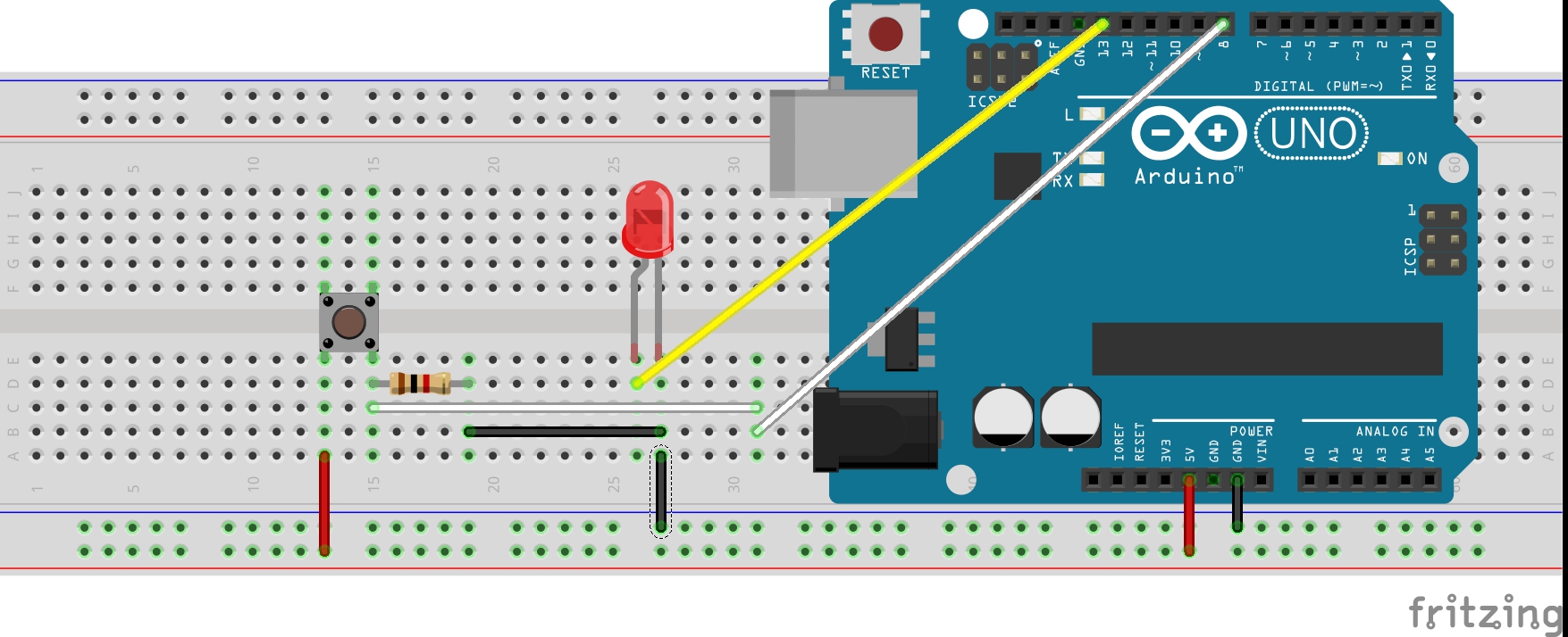
The first picture shows how to connect it :-
1. Red ---> 5V
2. Green ---> Gnd
3. White ---> Digital Pin 8 (Or whatever you wish , just remember to change the pin definition in the Sketch)
4. LED+ ---> Digital Pin 13 ( i would suggest not using another 220 ohm resistor)
5. LED- ---> Gnd (just beside Pin 13)
The second pic has the breadboard view......in case you want everything on bread board
Note :- Instruction about the code is commented nicely in the Sketch . Just download the first file and Upload it to the Arduino IDE......and plzz read the comments carefully.
Inference 1 :- I would like to hear it from the doers. Try to figure out why is this happening ,don't google it plzz. After figuring out go for the next objective.
Objective 2 :- After failing to do what you want, make a little function named "debounce()" to deal with the problem.
Things required :-
- Nothing required just the the second file attached.
Note :- Just upload the second file to the Arduino IDE and see the magic and again read the comments carefully.
Inference 2 :- Works exactly how it should i believe.
Conclusion :- So, you just made your first debounced switch........ok ok i know whats going on in your mind......you are thinking why do i need to know about debouncing to build a robot.....just be patient and move on to the next step.
Experiment Yourself :- Check out what Electrical noises are Google it or do whatever you like, repeat this Step Again and this time with out using the Resistor , Keep me posted what you saw.
Keep me posted for any doubts , queries and suggestion
Distance Sensor - HC-SR04 { Library Used - NewPing }
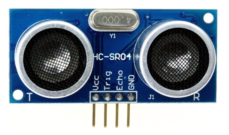
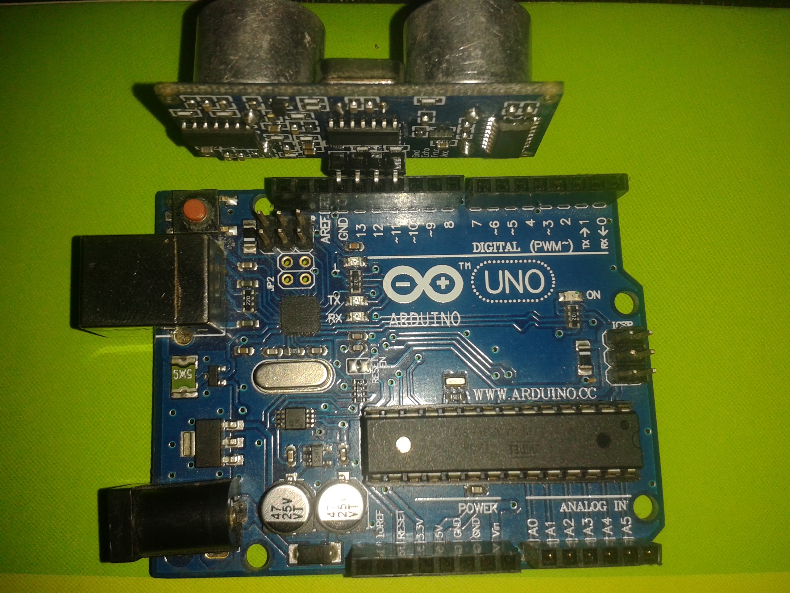
The library used in this objective is known as NewPing by Tim Eckel just to make the code much more simpler to understand for the beginners ..........For those who want to know more about how the function works.....i have also included a Sketch with details
For more details about different function and methods of NewPing library plzz vist :-
http://playground.arduino.cc/Code/NewPing#Methods
Objective 1 :- To add the NewPing Library to the IDE
Note :- Skip this Objective if you already know how to do it.
Step 1 :- Download NewPing.zip
Step 2 :- Open Arduino IDE
Step 3 :- Sketch menu > Import Library > Add Library
Step 4 :- Locate the NewPing_v1.5.zip
Step 5 :- Click Open
Step 6 :- Check out File > Examples > Find NewPing ....to confirm
Objective 2 :- To know some functions of the library and to play a bit with the sensor
Things Required :-
- 1XArduino UNO R3 (Or whatever you want) plugged to an USB cable to communicate with the computer.
- 1XHC-SR04.
Step 1 :- Attach the HC-SR04 as shown in the image
Gnd ---> Gnd
Echo ---> Digital pin 13
Trig ---> Digital pin 12
Vcc ---> Digital pin 11
Step 2 :-
Option 1 :- Copy the code from HC_SR04 .txt Upload it [ Understand first, then upload ]
Option 2 :- Open the IDE , Go to File > Examples > NewPing > NewPingExample . Then declare pin 11 as power pin , then set it to HIGH on the setup() function and change the 'echo' and 'trig' pin definition
[ Understand first, then upload ]
Note :- Opt for Option 2 , its better i think, i mentioned it in the previous step and i am also doing it now
Read the comments carefully, they describe everything [Do this for every Sketch]
Step 3 :- Open the Serial Monitor Ctrl + Shift + M . Play around with your hand for some time
Note : - if the distance is >=maximum distance set .......then the ping() function returns zero
Suggestion 1 :- Plz read the HCSR04.pdf file and the link mentioned above for better understanding.
Suggestion 2 :- Check out 'without_library_HCSR04.txt' file to know how to do it in your way without using the library and saving some program memory.
RF - RX and TX Modules { Library Used - VirtualWire }
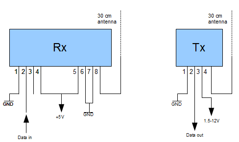
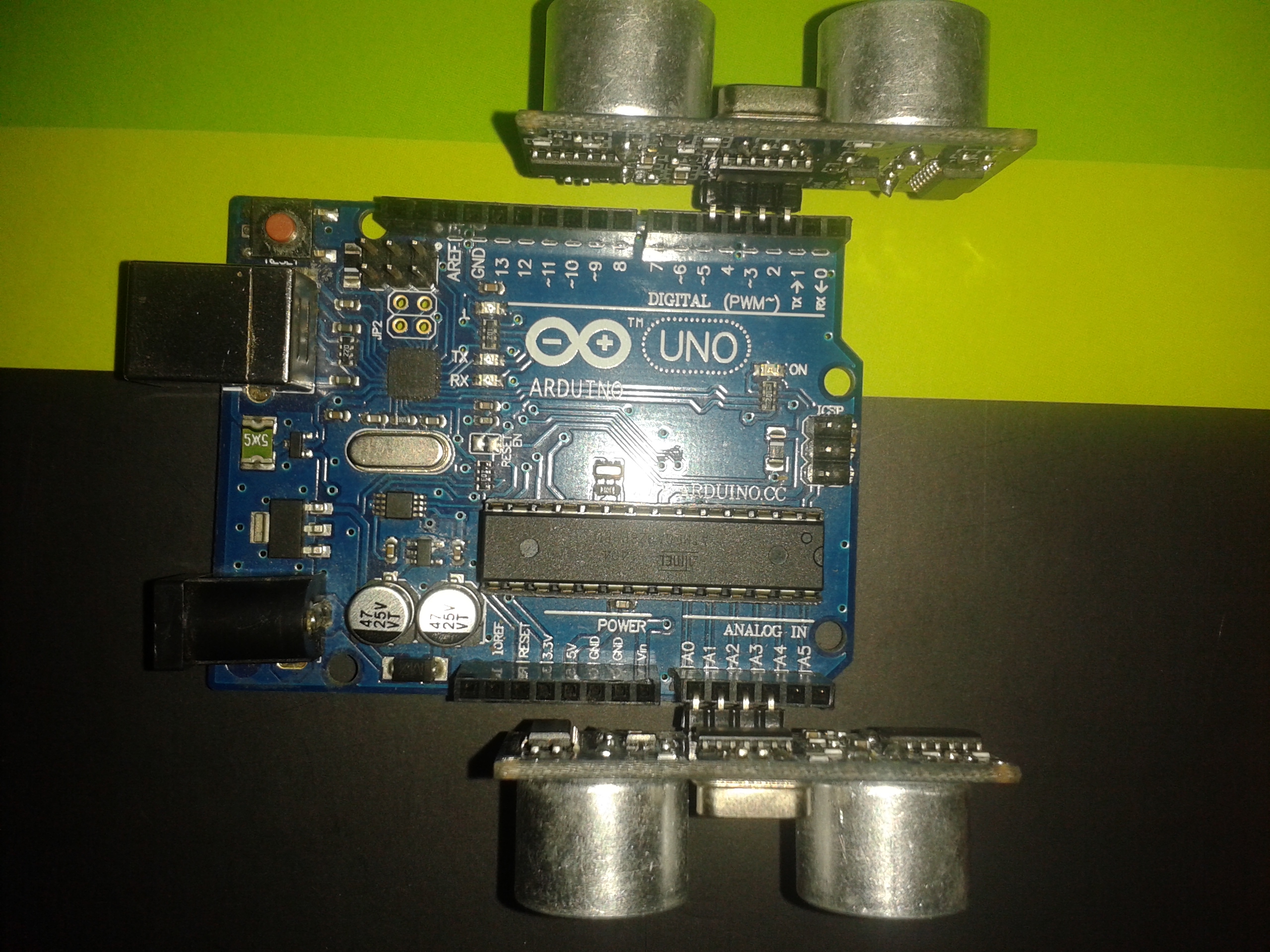
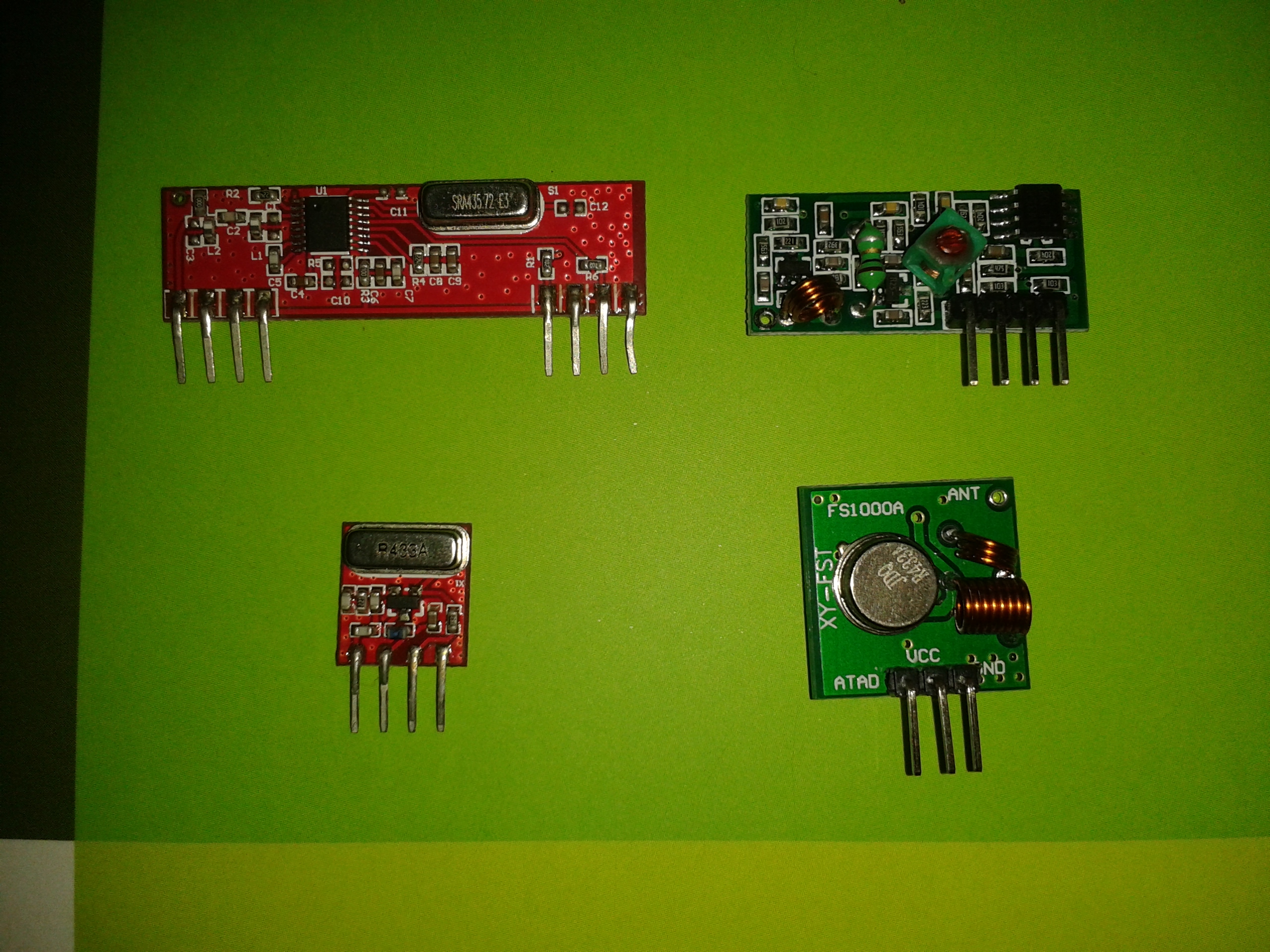

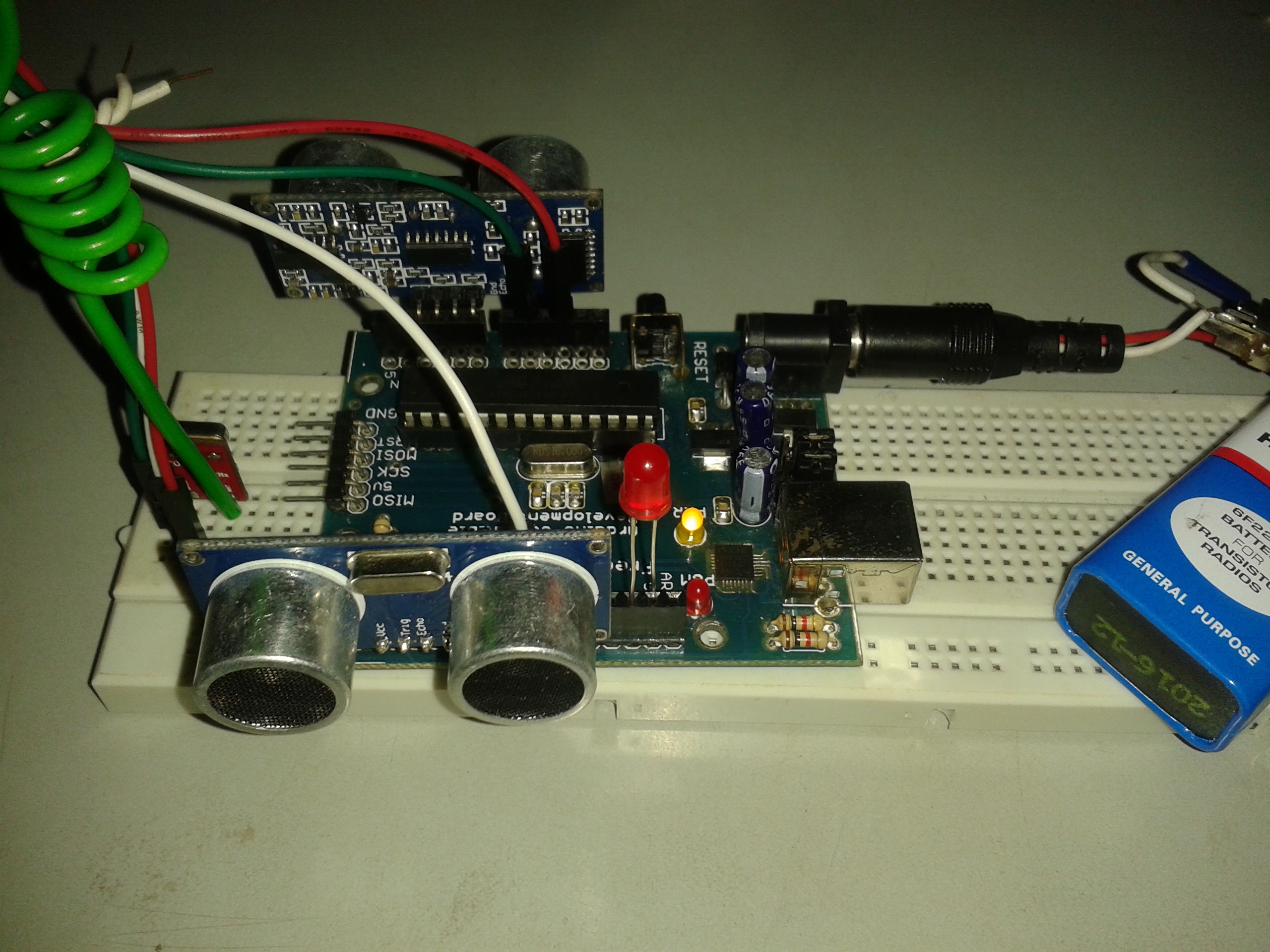
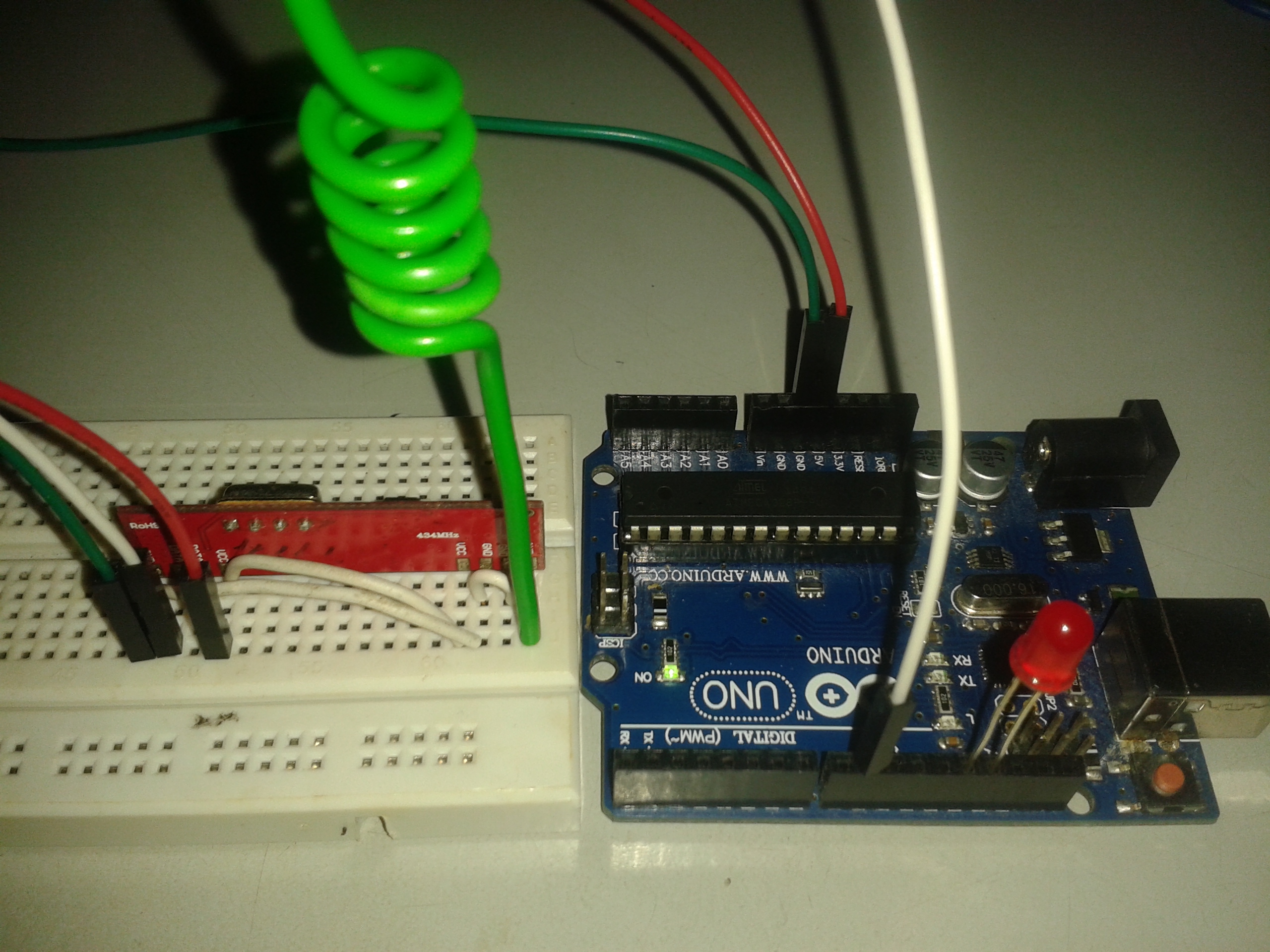
Now its going to be a little complicated .......the main objective is to send wireless data from two HC-SR04 into another Arduino which in turn will display the distances in the Serial Monitor via USB.......The RF_TX_test.txt may seem a bit confusing but go through the comments very thoroughly ........The New and Confusing Lines are explained in a way as simple as possible.......plzz keep faith move on to the next STEP you wouldn't believe whats coming.
Download the VirtualWire .zip file and Add it to the library
Plzz read the VirtualWire.pdf file first and ,then proceed.
Check out this instructable for better perception about those cheap RF - RX and TX modules
Objective 1 :- To wire up the TX module and the HC-SR04 to the Arduino and program it to send wireless data
Things Required :-
- 2 X HC-SR04
- 1 X Arduino [ If 2 Arduino boards are not available, then i would first suggest them to check the StandAlone Atmega Step first ] . You definately should have another Atmega then.
- 1 X Red LED
- 1 X BreadBoard [ People with 1 bread board plzz adjust somehow you will be needing two]
- 1 X RF - RX and TX module [ I used the Red one, there are many models available , feel free to choose]
- 1 X 30cm Wire [ the Helix effect in the picture is not necessary, just did it make the wire short in length ]
- 9v Battery and Snap with DC Jack and a Slide Switch [ To power the TX Arduino ]
- Jumper Wires [ As many required]
Procedure :-
- Check out the First image , and wire up the TX module to the Arduino
- Check out the Second image , and attach the 2 HC-SR04 as shown
- Go through RF_TX_test , and understand first , read the comments and instructions carefully
- Upload the RF_TX_test file attached. After Uploading you may see the LED flashing very fast
- Disconnect it from the Computer. Power it up with the battery
- Go to Objective 2.
Objective 2 :- To wire up the RX module to the Arduino and display the received distances to the Serial Monitor
Things Required :-
- 1 X Arduino [ If 2 Arduino boards are not available, then i would first suggest them to check the StandAlone Atmega Step first ] . You definately should have another Atmega then.
- 1 X Red LED
- 1 X BreadBoard
- 1 X 30cm Wire [ the Helix effect in the picture is not necessary, just did it make the wire short in length ]
- Jumper Wires [ As many required]
- Some small wires (Optional) [ Just to make the wiring neat ]
Procedure :-
- Check out the First image , and wire up the RX module to the Arduino.
- Your wiring should somewhat look like the last picture.
- Go through RF_RX_test , and understand first , read the comments and instructions carefully.
- Upload the RF_RX_test file attached. After Uploading you may not see the LED flashing coz probably the TX Arduino is switched off.
- Switch On the TX Arduino and after the LED starts flashing.
- Reset the RX Arduino once. Then the RX LED will start flashing after a second
- Ctrl + Shift + M to Open the Serial Monitor
- Check out the readings.Play with your hands a bit and check the change in data.
Inference :- Thus you got both wireless and Serial Data Communication. Seems like we are going somewhere interesting now i believe. Just wait and watch.
Suggestion :- Don't rush it and be patient and curious both, just take you time.This is not a single day project.
Stepper Motor(28BYJ-48) Control [AccelStepper]
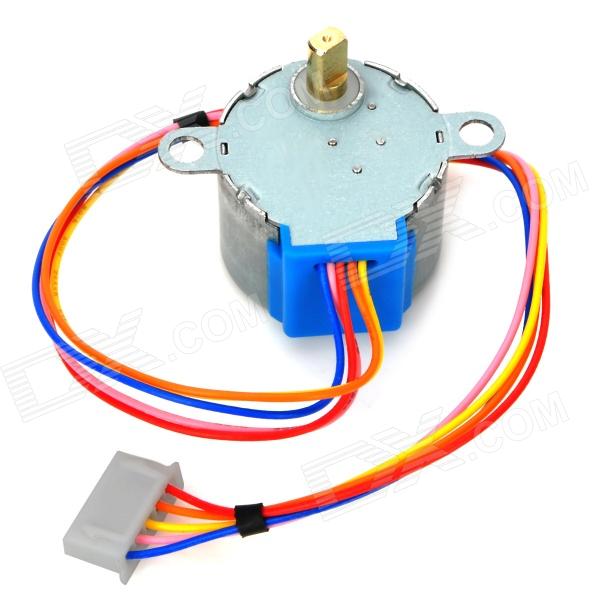

The 28BYJ-48 is a 5v Stepper, the most commonly used Stepper for Arduino , confused to see the Push Button image again, told ya we will do something very interesting with it now . Much more to explore just be patient
Check out this instructable Great Job done by Mohannad Rawashdeh [This was the first instructable which i tried when i first started with 28BYJ-48]
But my one is a bit easier i believe , coz i am a using a library named AccelStepper
First download AccelStepper.zip and Add it to the library
Then go through the docs folder and read the classAccelStepper-members .html file , it would help understanding the Sketch
Objective 1 :- To rotate a stepper motor clockwise and anti-clockwise using a Darlington transistor array (ULN2003)
Things Required :-
- 1 X Arduino board connected to the computer
- 1 X BreadBoard
- 1 X Stepper Motor (28BYJ-48)
- 1 X L7805CV (Or any other 5 v voltage regulator should work) (The DataSheet may help)
- 1 X ULN2003 Transistor Array IC
- 1 X 100 uF electrolytic capacitors
- 1 X 10 uF electrolytic capacitors
- 1 X Heat Sink (Optional)
- Jumper Wires (As many required)
- 9v - 12v external power source
Procedure :-
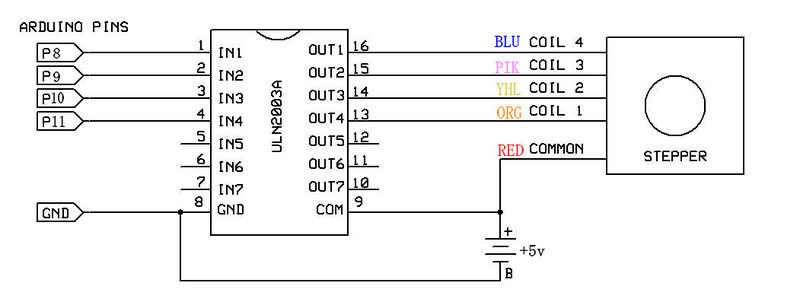
- Connect the Stepper motor to ULN2003 as shown on the schematic (Figure 1)
- Connect the pinouts from ULN2003 to the Arduino as shown on the schematic (Figure 1)
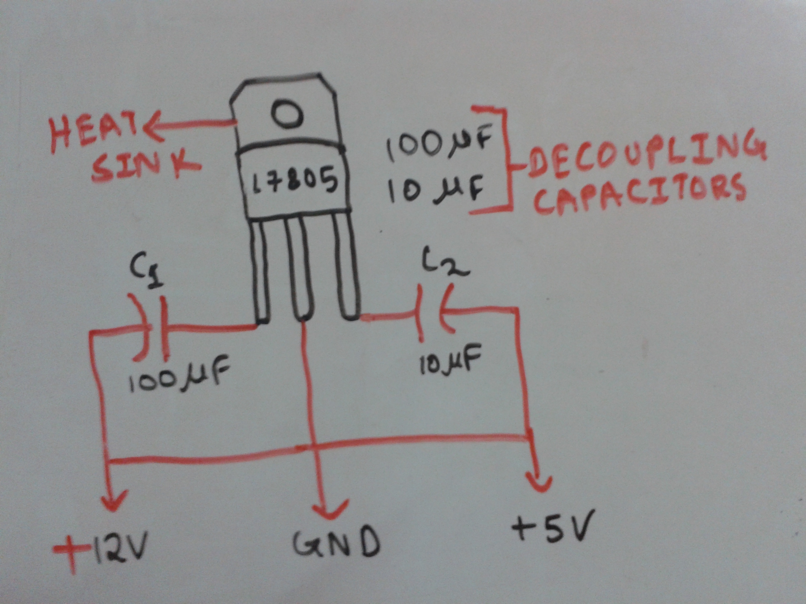
- Check the third image and connect the de-coupling capacitors to the voltage regulator (i dont really know much about the decoupling capacitors plzz feel free to explain me if i am wrong).
- Connect the (5V) output voltage pin and the GND to the transistor array
- There should be a common ground from the ULN2003 to the Arduino too. As shown in the 1st pic.
- Plug in the power source
- Understand and Upload the Sketch "AccelStepper_test .txt"
You should see that the Motor rotates once clockwise and then once anti-clockwise and repeats.
Objective 2 : - To control the clockwise rotation with a Push Button
Things Required :-
- Everything mentioned above.
- 1 X Push Button Switch.
- 1 X any resistor greater than 1k ohm
Procedure :-
- Just do exactly what was said in Objective 1
- Connect the Switch to the Arduino just like it was done in Step 1 . Just that this time the white jumper goes to Digital Pin 7
- Understand and Upload the Sketch "button_controlled_stepper.txt"
- Push the Switch to see the effect .
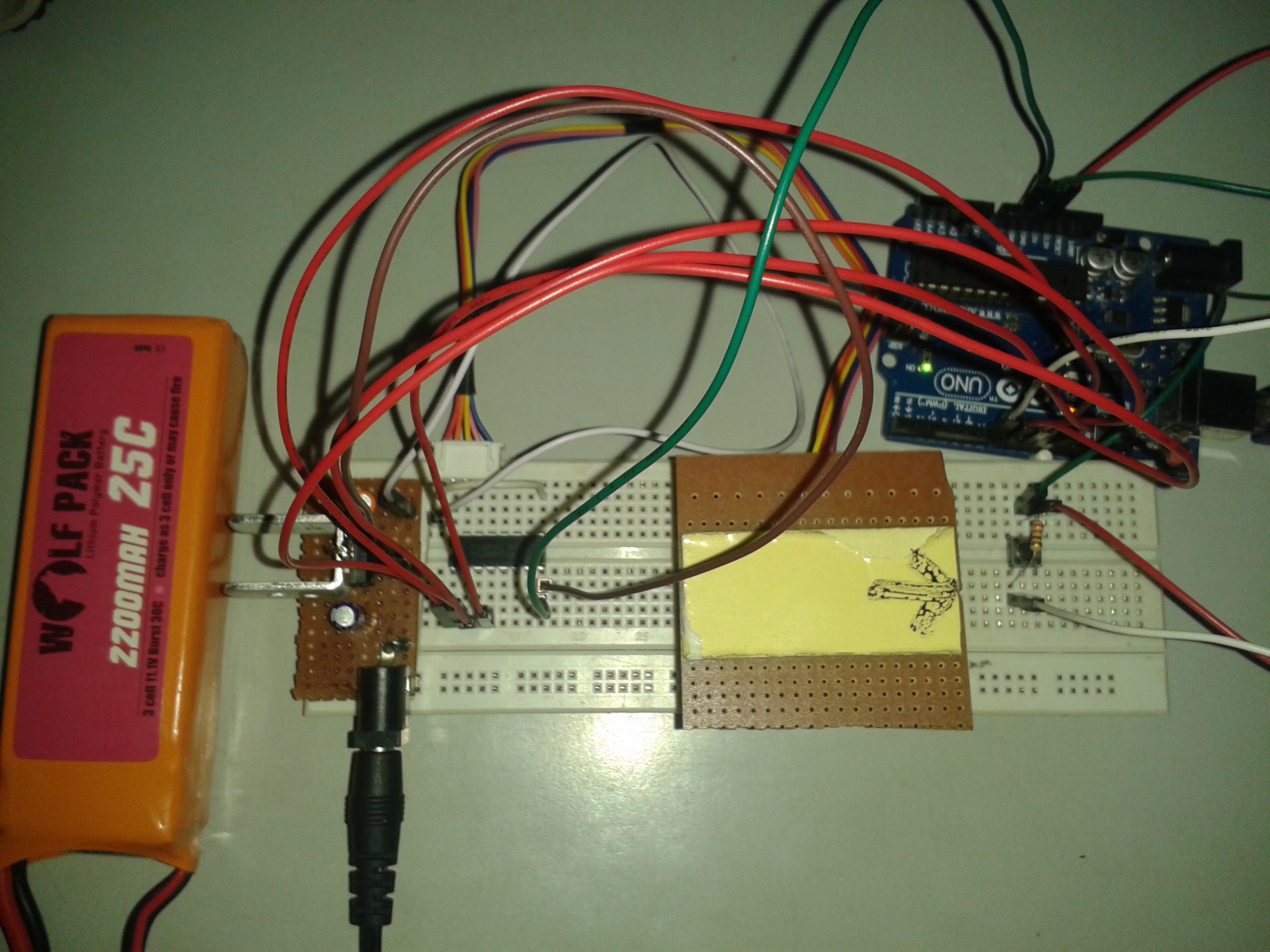
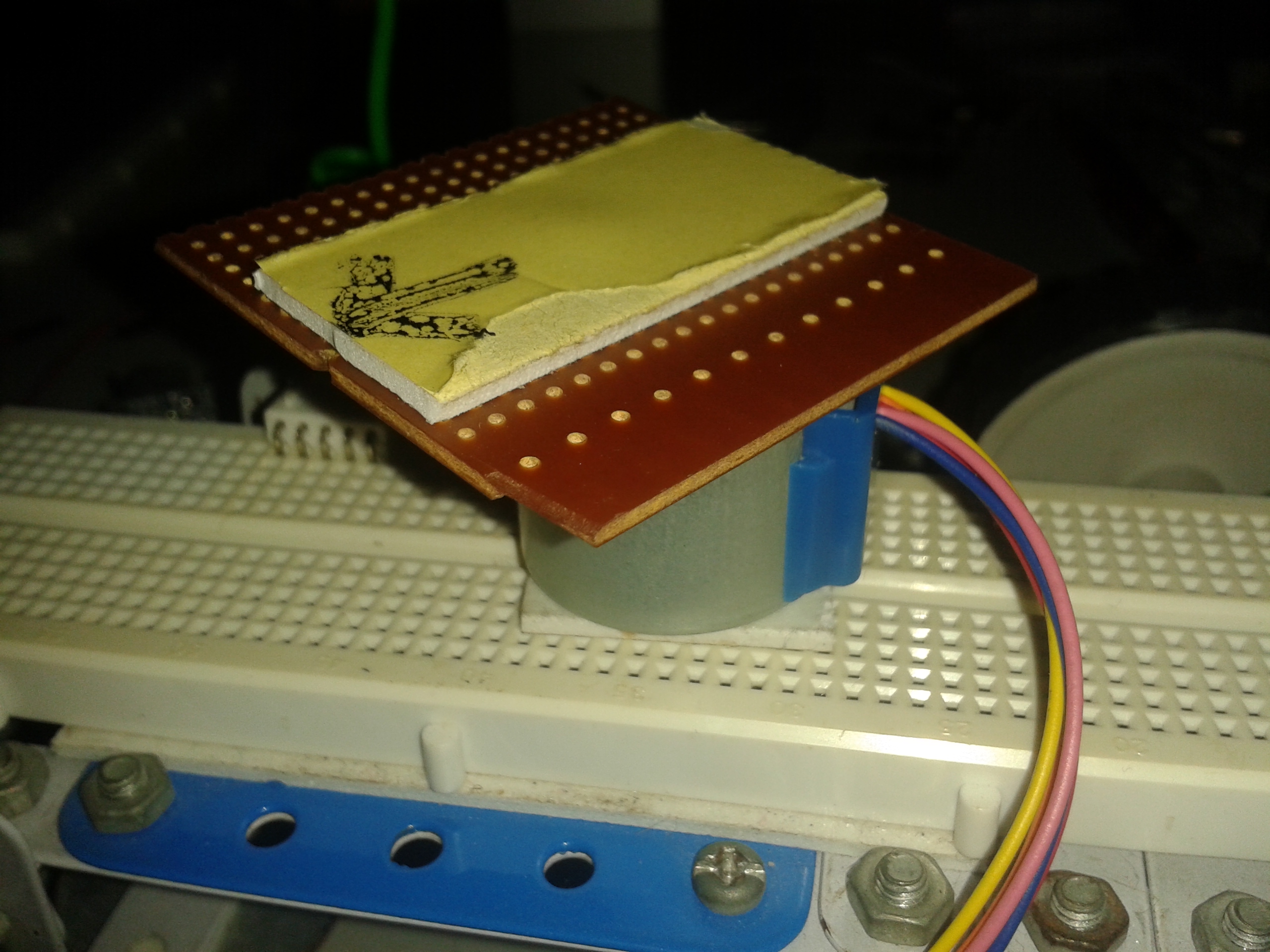
Your final work should look somewhat like the 4th picture i believe. Ignore the arrow and the platform over the stepper motor for now, but you will need it later on while making the Robot.
Check out the video if you want to.
Note :- The Stepper will rotate only 10 times , if you want to rotate it more, just press the Arduino's reset button.
Suggestion :- Read the AccelStepper library's docs. And again read the comments slowly but steadily
More Steps you go more Interesting it becomes , isn't it ?
DC Geared Motor Control (L293D)
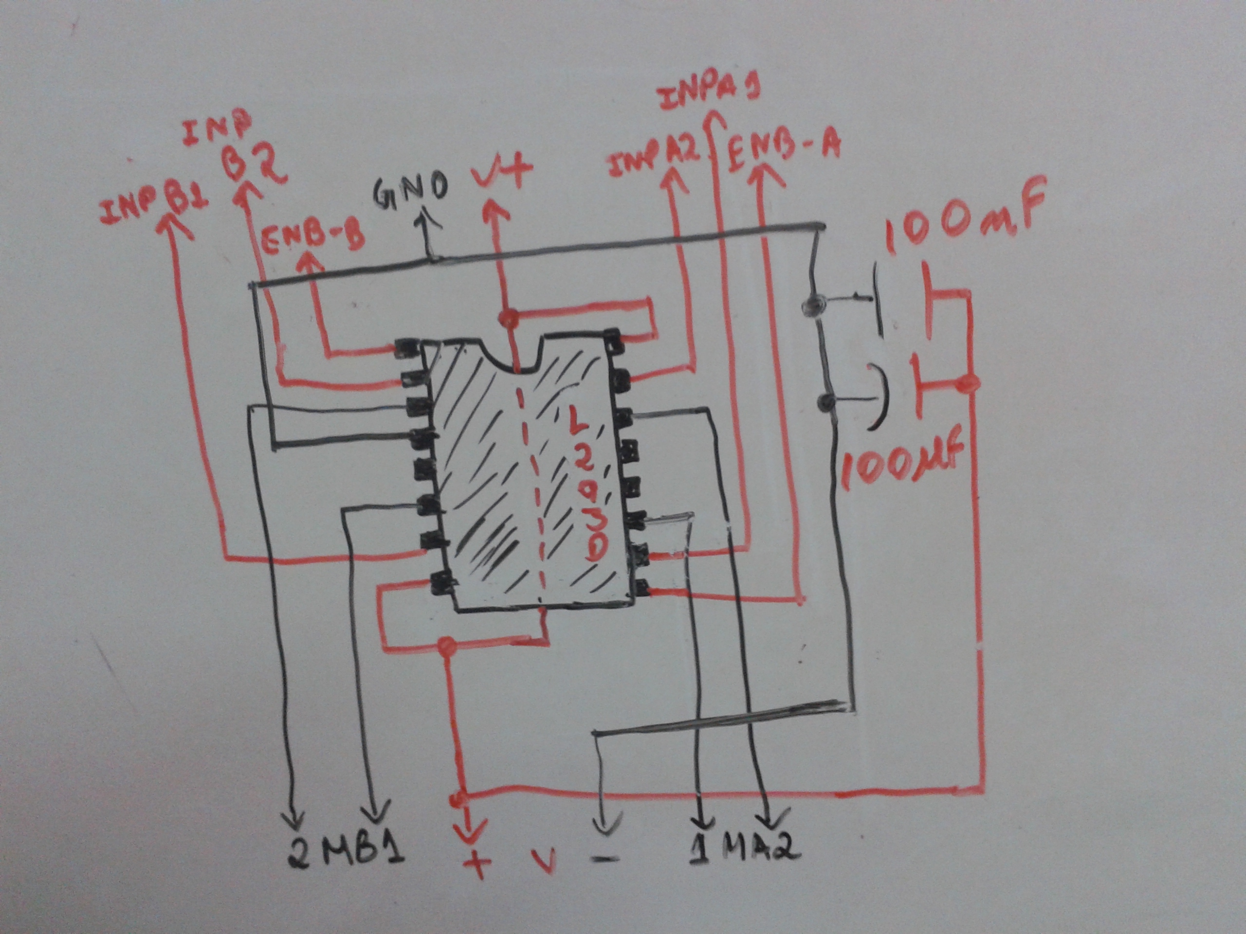
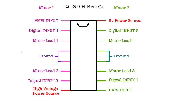
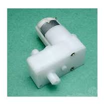
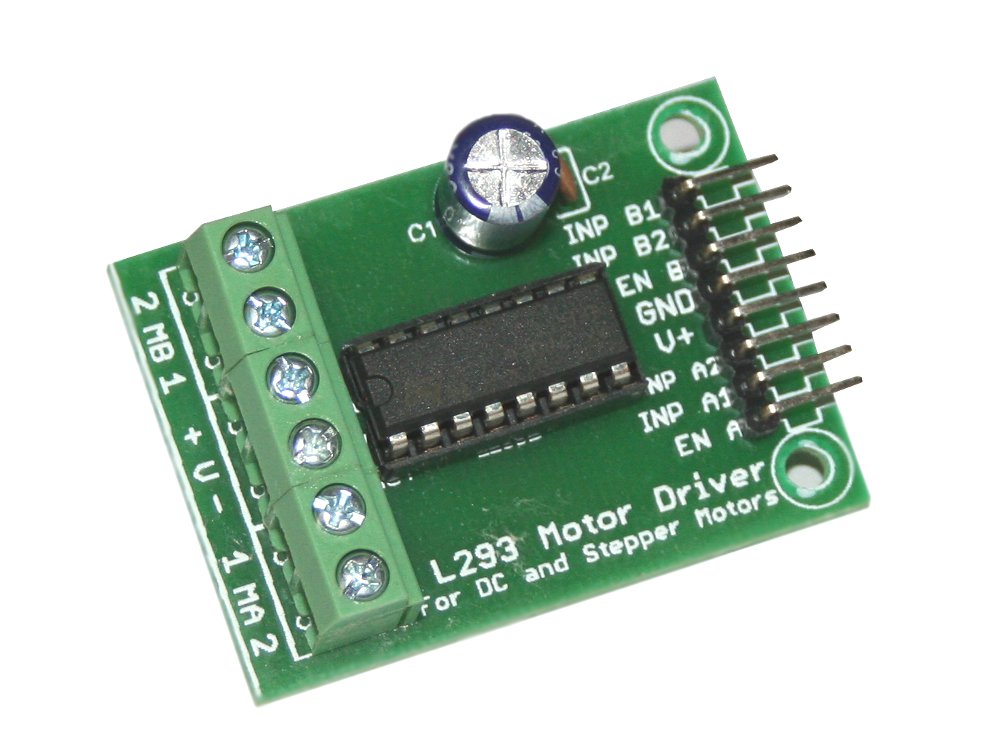

This tutorial is the most easiest and Mostly important , this is the thing which will make the Robot a Rover
This tutorial will be very easy to follow and not so complicated code
Objective :- To Check that two DC- Motor is working as we want it to using a motor driver
Things Required :-
- 2 X Geared DC BO Motor (Offset or any other DC motor will work just fine)
- 1 X L293D Motor Driver Module ( Can make it Stand Alone too ).
- 1 X Bread Board
- Jumper Wires (As many required)
- 1 X Arduino Dev Board(UNO or whatever)
- 1 X L7805 5v voltage regulator ( from previous tutorial )
- 1 X 10uf Electrolytic Capacitor ( from previous tutorial )
- 1 X 100uF Electrolytic Capacitor ( from previous tutorial )
- 1 X 100nF Ceramic Disc Capacitor (Optional)
- 1 X 100uF Electrolytic Capacitor (Optional)
- 1 X 9 - 12 V Battery
Procedure :-
- Setup the Voltage regulator with the de-coupling caps just like the previous tutorial.
- Just like in the schematic for L293D connect the four terminals of the DC motor to the driver Note :- MA - Motor A...........MB - Motor B, the final Output result will totally depend on how you connected the Motor to the Driver.
- If you do not have a Driver Module then connect two caps (100nF and 100uF ) on the bread board as shown in the schematics
- The upper pin outs,all of them goes to the Arduino except the V+, it is just for any alternative power source INP-A1, INP-A2, INP-B2, INP-B1 goes to Arduino pin 2,3,4,5
- Connect the Vin as shown in the image, the dotted line dividing the Driver actually signifies that the wire is under the motor Driver , use your Analyzing skills and make all the connection properly Note:- Wrong connection can permanently damage your Motor Driver (Know it from experience)
- Connect the lower V+ and V- to the Battery
- Understand and Upload the program to the Atmega.
- Plzz dont be baffled to see unexpected results , its just because of you motor connection
- Play around with the code , change the delay() s , add new function , and do some experimentation
- Change the pattern of the Input Pulses to match you Motor connection
Conclusion : - Can you get some hint about How the robot is going to work , i am clearly going to define what its going to do just wait for it.Keep me posted with doubts and suggestions.
Downloads
The Brain Stands Alone ?
20110821-6067-176tx2q.png)
.jpg)
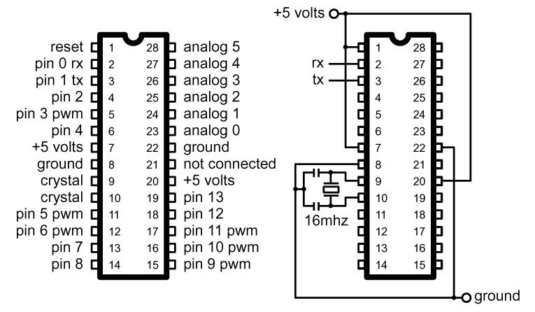
The Atmega is literally the brain of the Arduino , and Also it can Stand Alone without the Arduino dev board, Lets see how z that possible
Objective 1 :- To make the Atmega 328 work on a bread board
Things Required :-
- 1 X Arduino UNO(the SMD versions of Arduino wont work)
- 1 X Bread Board
- 1 X 150 -250 ohm resistor (I used 220 ohm )
- 1 X Red LED
- 1 X 16 MHz Crystal Oscillator
- 2 X 22pF Ceramic Disc Capacitors
- Some small wires or Jumper Wires [ As many required ]
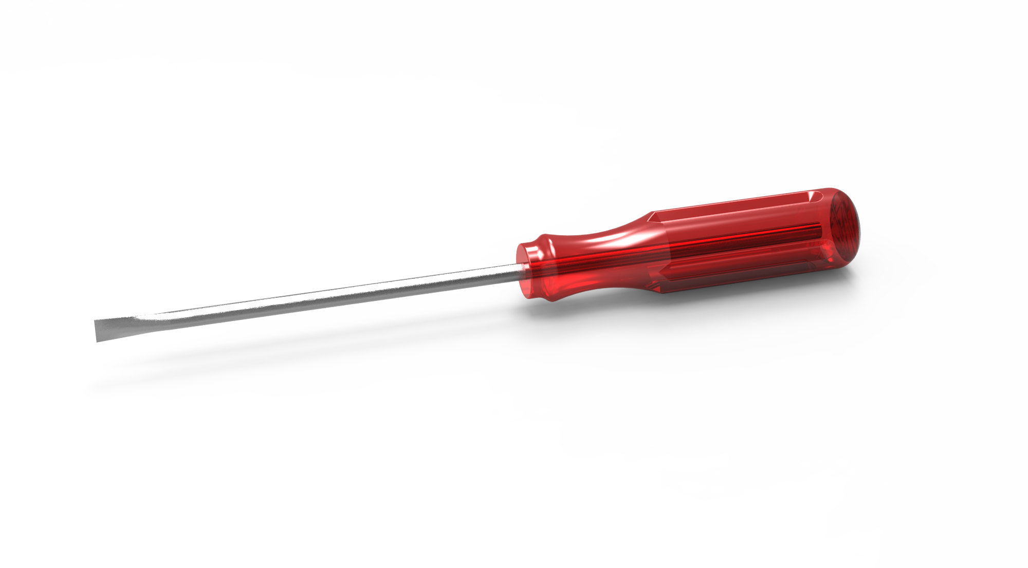
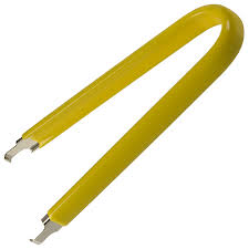
- IC Extractor , or a Screw Driver , as shown on the images
Procedure :-
- Connect the Arduino to the Computer
- Open the IDE
- Go to File > Examples > Basics > Click on Blink
- Upload the program to the Microcontroller (Atmega 328 (DIP) )
- Disconnect the Arduino
- Extract the Atmega out of the board carefully either using a Screw driver or an IC Extractor ( Its much easier to do with a Screw Driver but a lot Safer to do with an Extractor) . Be careful the pins may bend.
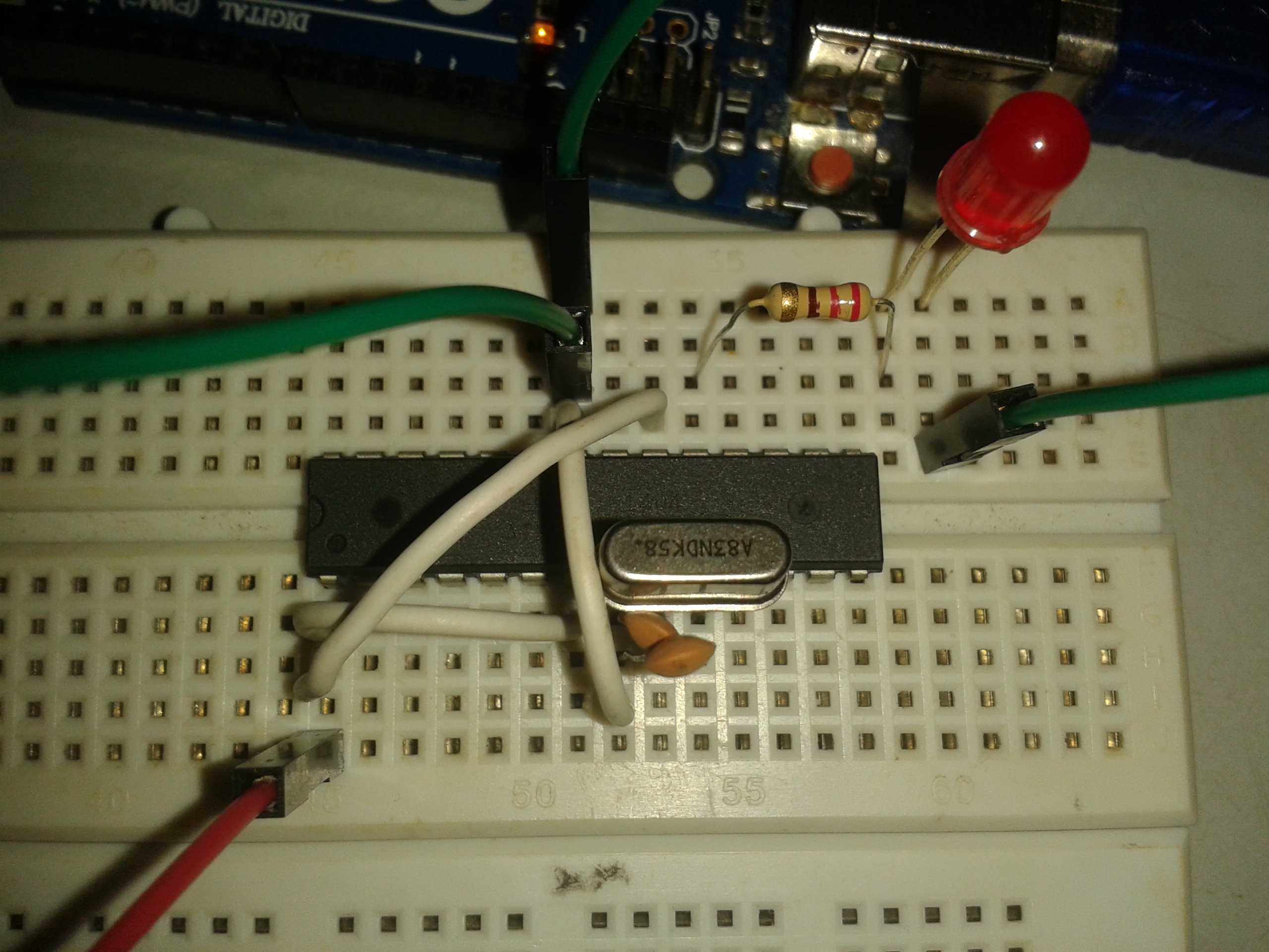
- Fix it in a Bread Board , as shown in Figure 2.
- Follow the schematics(Image 1) and connect the Crystal and the Capacitors and carefully do the gnd and Vin connections using some small wires
- Attach the LED and the resistor in serial to Digi Pin 13 and Ground the Cathode
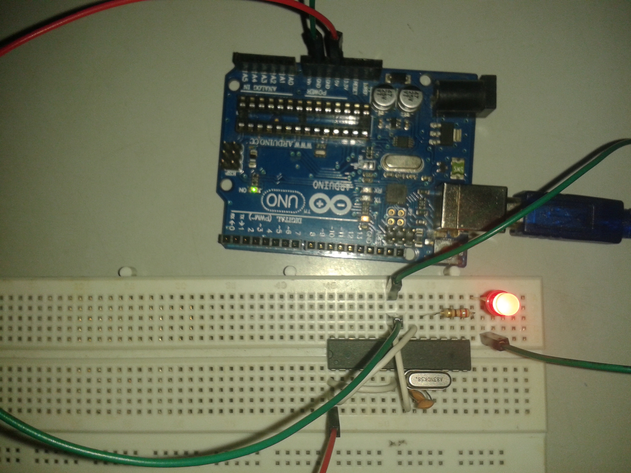
- Take the 5v and Gnd feed from the Blank Arduino Board to power the Atmega microcontroller. Connect the Arduino board to the computer. Check out the 3rd picture.
Note :- The Arduino Board can still feed 5v , 3.3v ,Gnd, and Vin, even when the Atmega is absent . Don't power the board above 5 V , this may damage the Micro controller permanently
Conclusion :- The LED should Blink as it should have while on the Development board . Hurrah! The Brain Stands Alone
Suggestion 1 : - To those who don't have 28 pin DIP Atmegas they should probably buy some Atmegas ( 3 X Atmega 8A PU to be exact, they come for around $1.5 / piece) You will need them later on for the rover.
Suggestion 2 :- To those who want to program the microcontroller with another Arduino while its standalone check out this link , its quite awesome.
I hope you all liked so far , if someone is disappointed with anything plzz feel free to comment and help improve the tutorial. Once again to clear doubts is my first priority, so keep me posted.
Serial Communication Between 2 StandAloned Atmega Microcontrollers
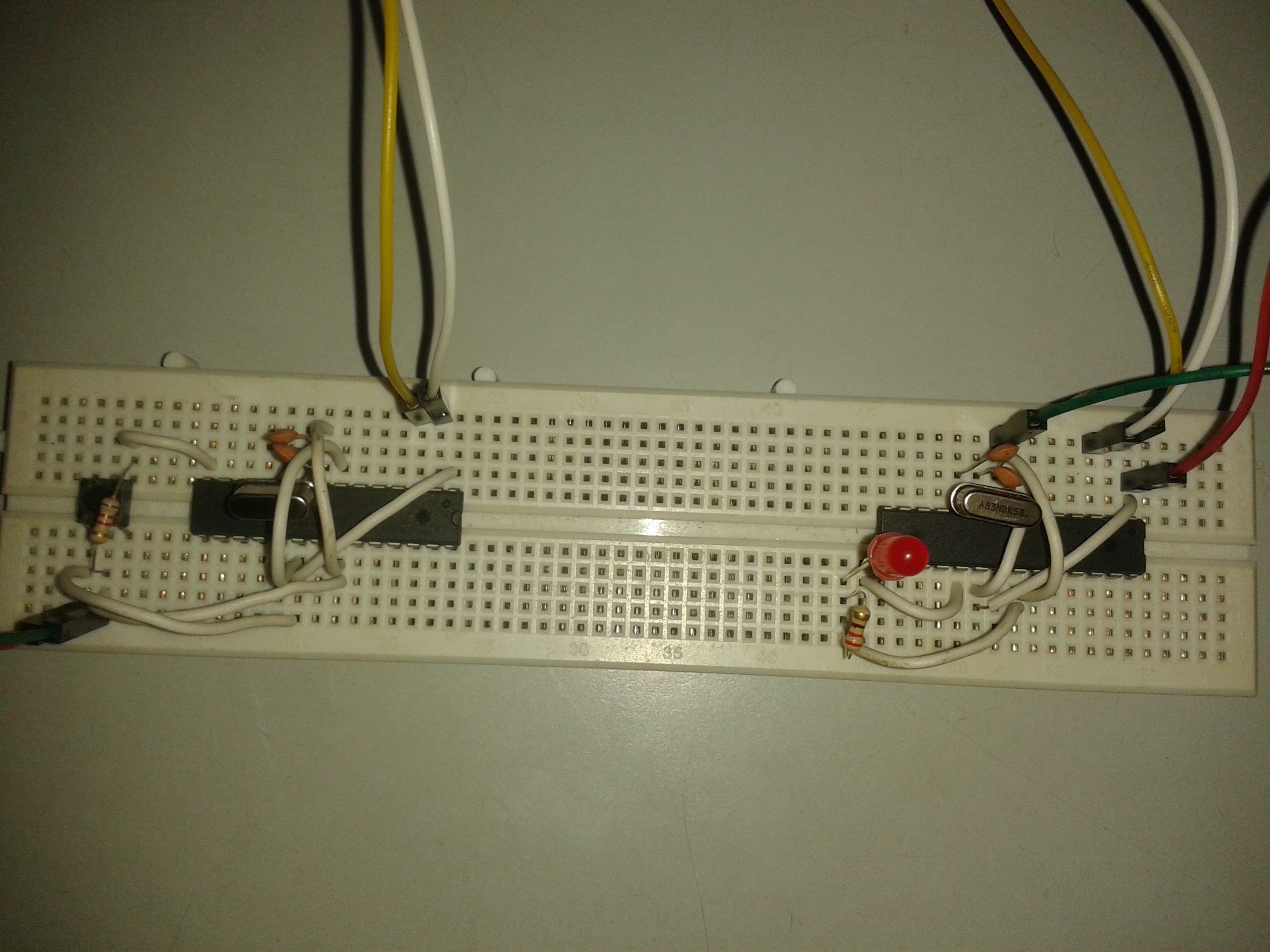


You did Serial Communication with The Computer many times on the previous Steps . But microcontrollers are also tiny Computers indeed. So did you ever wonder about How to have Serial communication between two microcontrollers. That's what this tutorial is all about.
This will be one of the most easiest tutorials in this instructable if you have done the Steps below sincerely :-
Step 1 : Switch Debouncing (Software)
Step 6 : The Brain Stands Alone ?
Objective : -To have Serial communication between two Atmega 328 microcontrollers
Things Required :-
- 2 X Atmega 328 PU microcontrollers
- 2 X Arduino UNO ( One Board will also do , the bootloader should be installed)
- 1 X Bread Board
- 1 X RED LED
- 1 X Push Button Switch
- 1 X 1k ohm or greater resistor
- 1 X 150 - 250 ohm resistor ( I used 220 ohm )
- 4 X 22pF ceramic disc Capacitors
- 2 X 16 MHz crystal oscillator
- Some small wires and Jumper Wires ( As many required )
Procedure :-
- Plug In the Arduino .
- Analyze the code and Upload the Sketch "TX_Atmega .txt" .
- Disconnect and Extract the Atmega out of the board. Fix the microcontroller to the left side of the bread board as shown in figure 1, then standalone it just like in the previous Step(without the led and resistor)
- Fix another Atmega to the Arduino UNO.
- Connect the Arduino to the computer.
- Analyze the code and Upload the Sketch "RX_Atmega .txt" .
- Disconnect and Extract the Atmega out of the board. Fix the microcontroller to the right side of the bread board as shown in figure 1, then standalone it just like in Step 6. Just that this time the Led pin is assigned to digi pin 9
- For the left microcontroller connect the switch and the 1k ohm resistor as it was demonstrated in STEP 1 just beside the microcontoller.
- See the schematics and connect the TX pin in the LEFT Atmega with the RX pin in the RIGHT Atmega, then power both the Atmegas with just like in Step 6 , and also power the push Button.
- See what happens when you press the push Button Switch.
Note :- If the Arduino bootloader is not installed in the microcontroller i would suggets them to visit ArduinoISP page
Conclusion :- The Easy concepts ends with this Step, in the next Step i will describe fully about the concept of JAAR and you will know why all these tutorials are so important.
JAAR - Just Another Autonomous Robot ( the Concept )
Getting Straight to the point
Primary Things Required :-
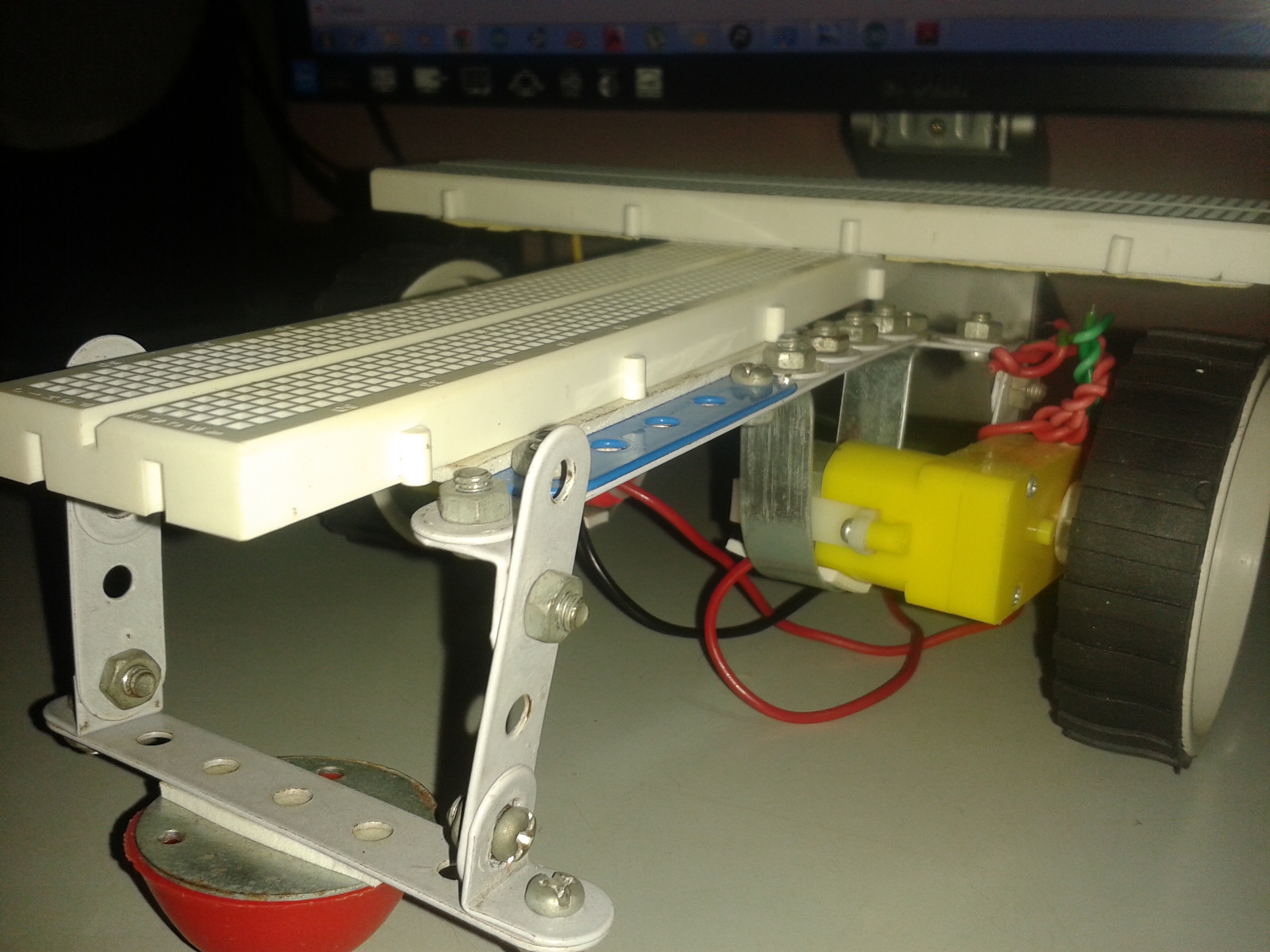
- 1 X Chassis with two DC - Motor and Wheel Affixed ( Figure 1 )
- 2 X Atmegas microconttroller
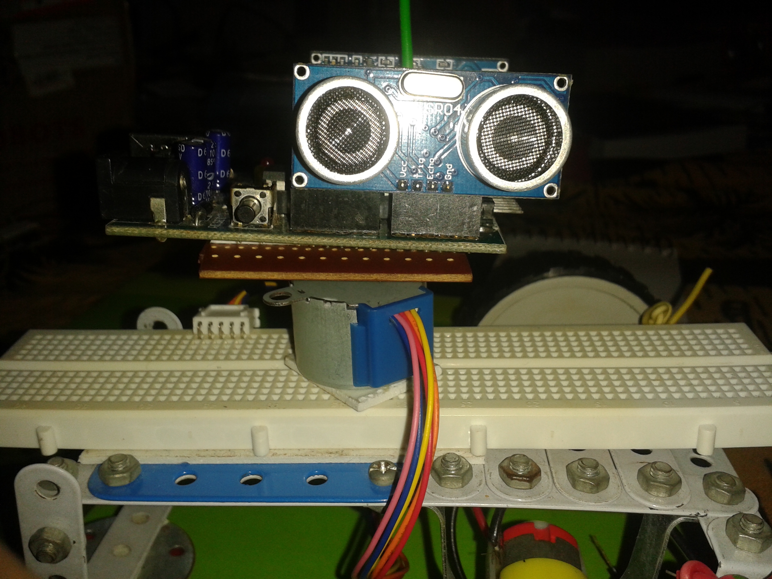
- 1 X Stepper Motor( 28BYJ-48 5V ) with a platform (Figure 2)
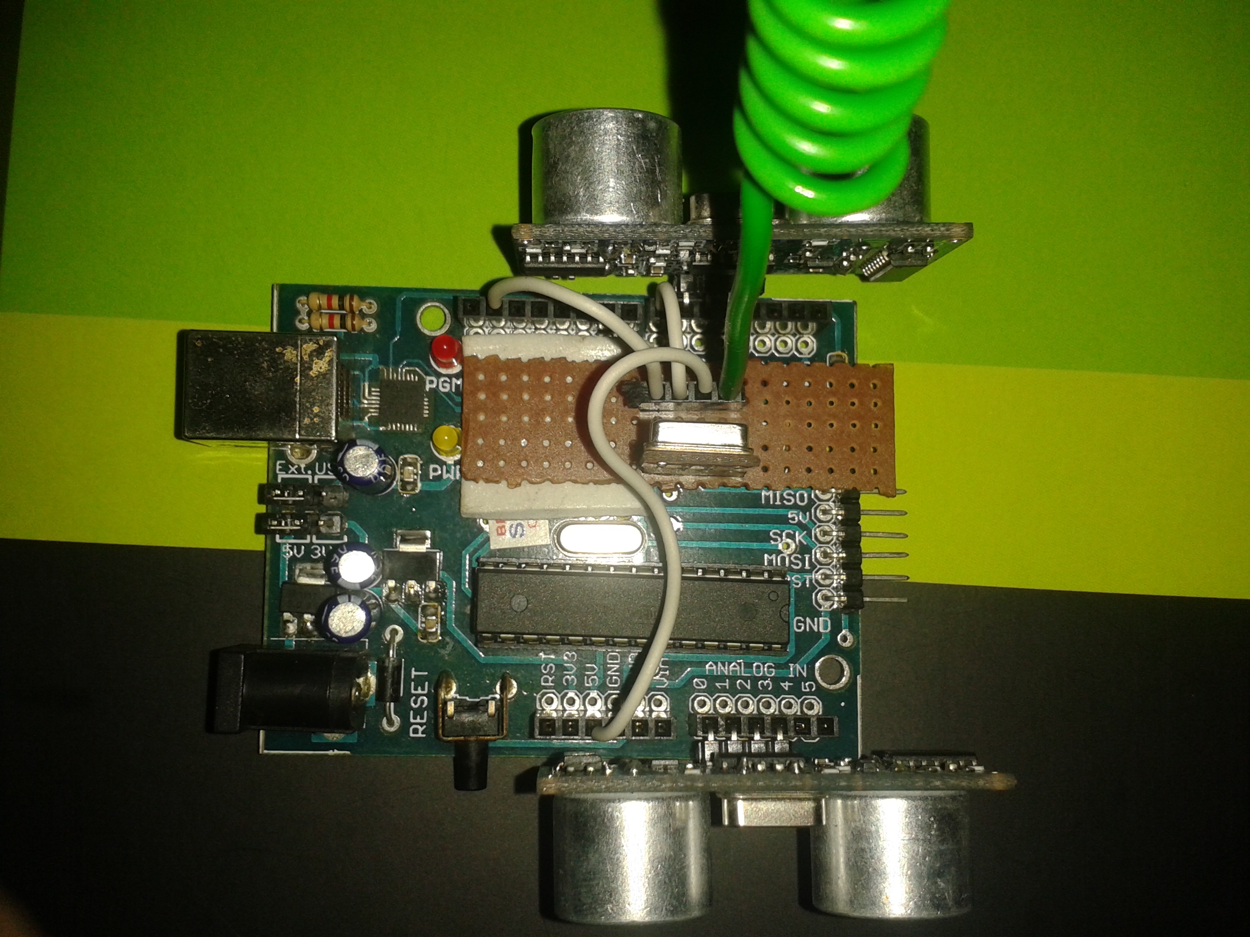
- 1 X RF- RX and TX module (Figure 3)
- 1 X Arduino Development Board with a Atmega 328 pu microcontroller (Figure 3)
- 2 X HC-SR04 (Figure 3)
- 1 X ULN 2003
How everything will work :-
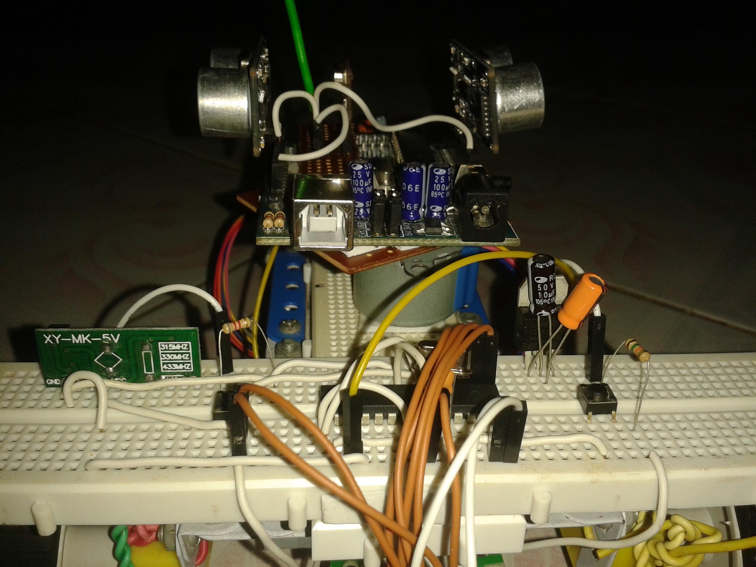
- Check out the 3rd image. This will be the Transmitter Section
- The Transmitter Section will be on top of the Stepper Motor platform.
- Now you may get some idea about the concept , yahh you guessed right the whole platform will rotate with the Stepper Motor
- The Rotating Transmitter Platform will send wireless distance data of both the HC-SR04 every 5.625 degrees moved from the initial position that is exactly 64 steps for the Stepper Motor
- This Stepper goes 4096 steps for 1 complete rotation . Every 64 steps the distance sensor will be pinged (triggered) and the distance data will be sent wireless to another Atmega which is Fixed to the Bread Board
- So there will be 4096 / 64 distance data per HCsr04 , that is 128 distance data total to be sent for 2 HCSR04
- Those 128 data which has been transmitted will be processed and a SONAR map of the obstacles within 200 cm will be created and it will get updated after every rotation.
- By processing the map the DC MOTOR will react to the obstacles
Where the problem lies :-
1. Sound is itself the problem, it gets absorbed , reflected and needs a fair amount of area to actually detect any obstacle
2. If you unplug the whole robot while it is rotating the Stepper Motor gets misplaced from its initial position again while start up the robot thinks the misplaced position to be its initial position .
Solution :-
1. This step cannot be changed for now , but i will surely do sometime later on , in another Instructable
2. Check out the Last image to see its solution. The idea's quite simple , a human needs to adjust it .
See how interesting it has become now, we have come a long way from debouncing a switch . But see its just another obstacle avoiding robot , just comes with a different concept.
For any queries or suggestion plzz feel free to comment
Wiring Up JAAR - Implementing Your Understandings

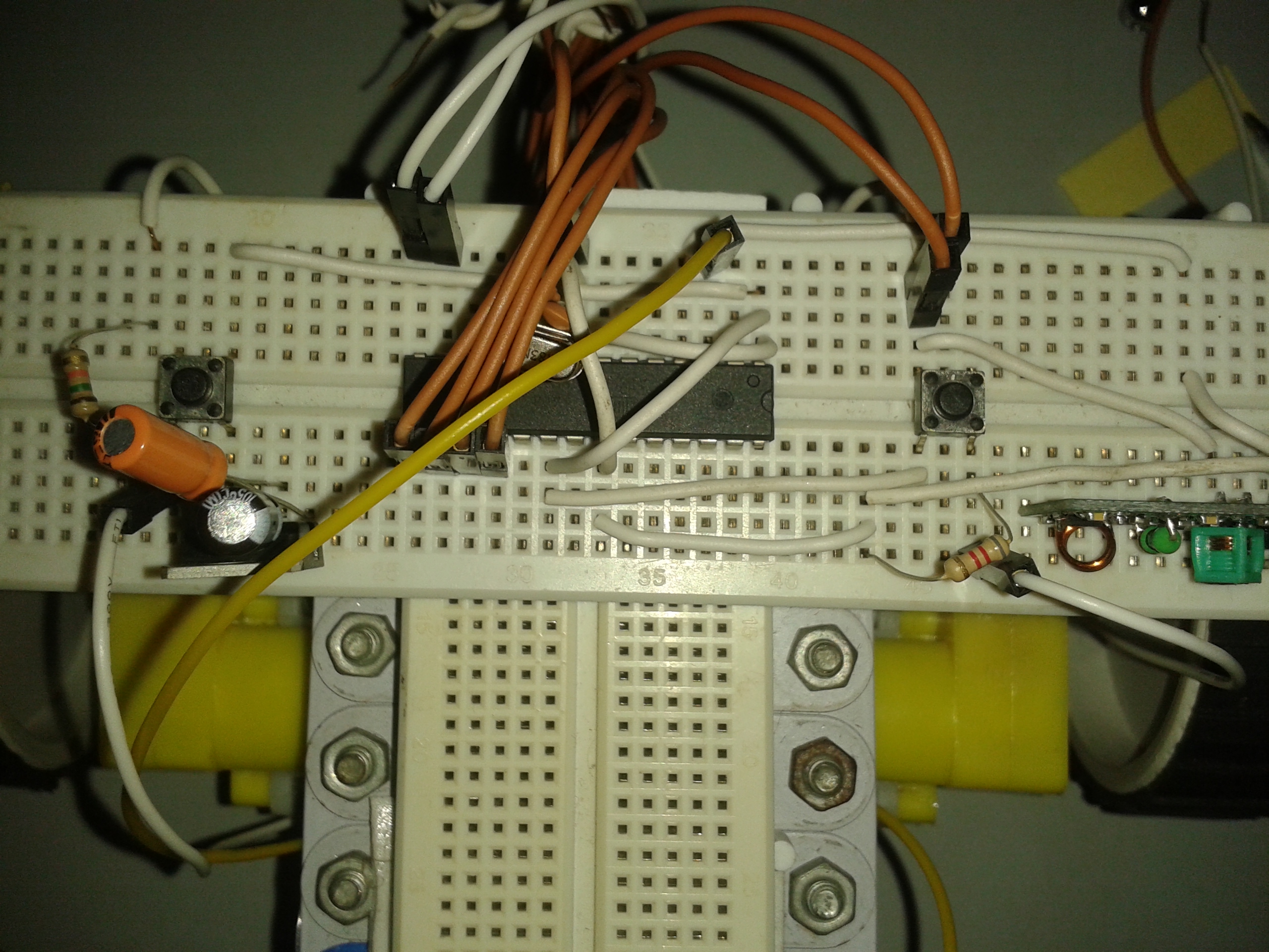
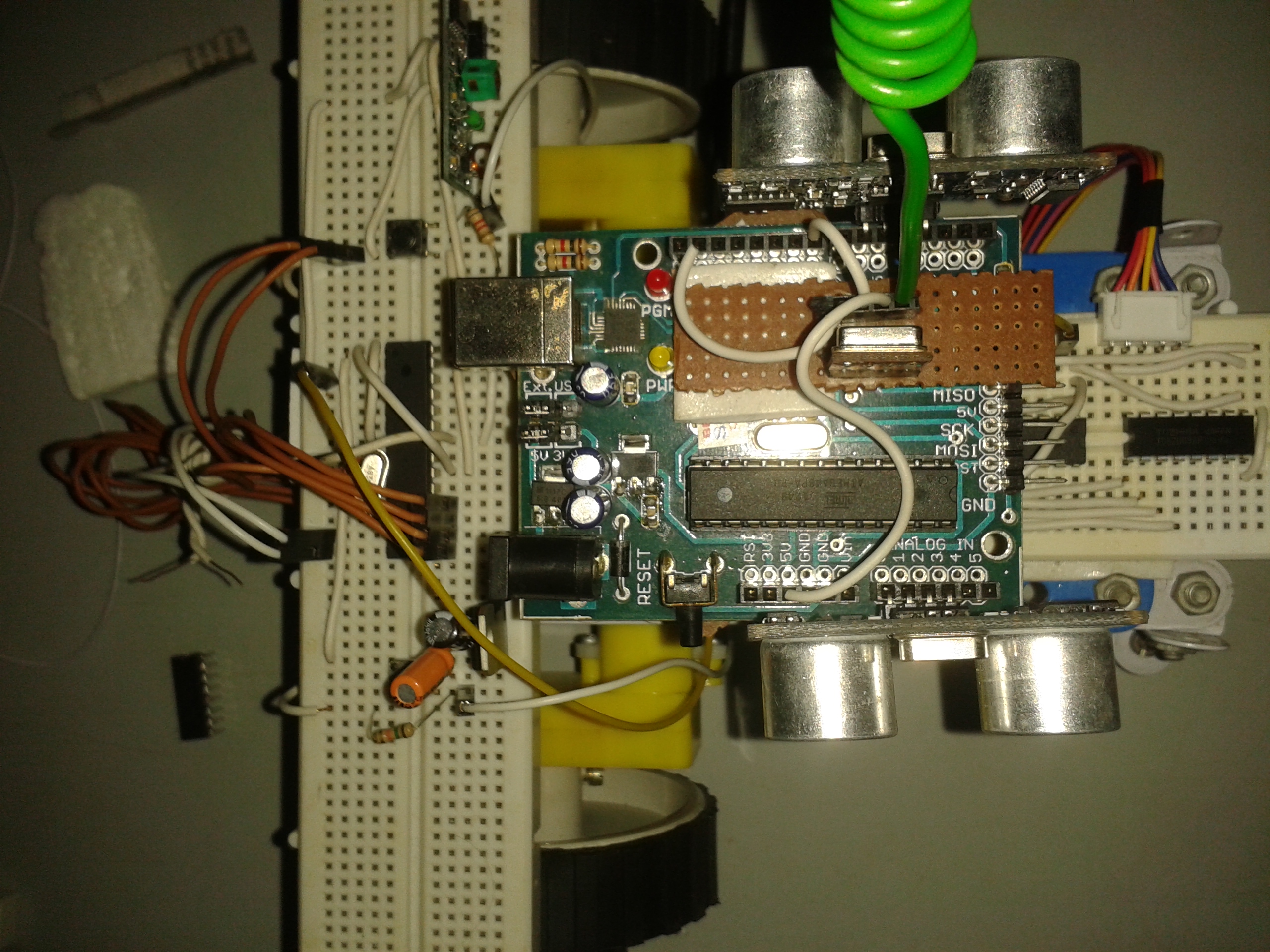
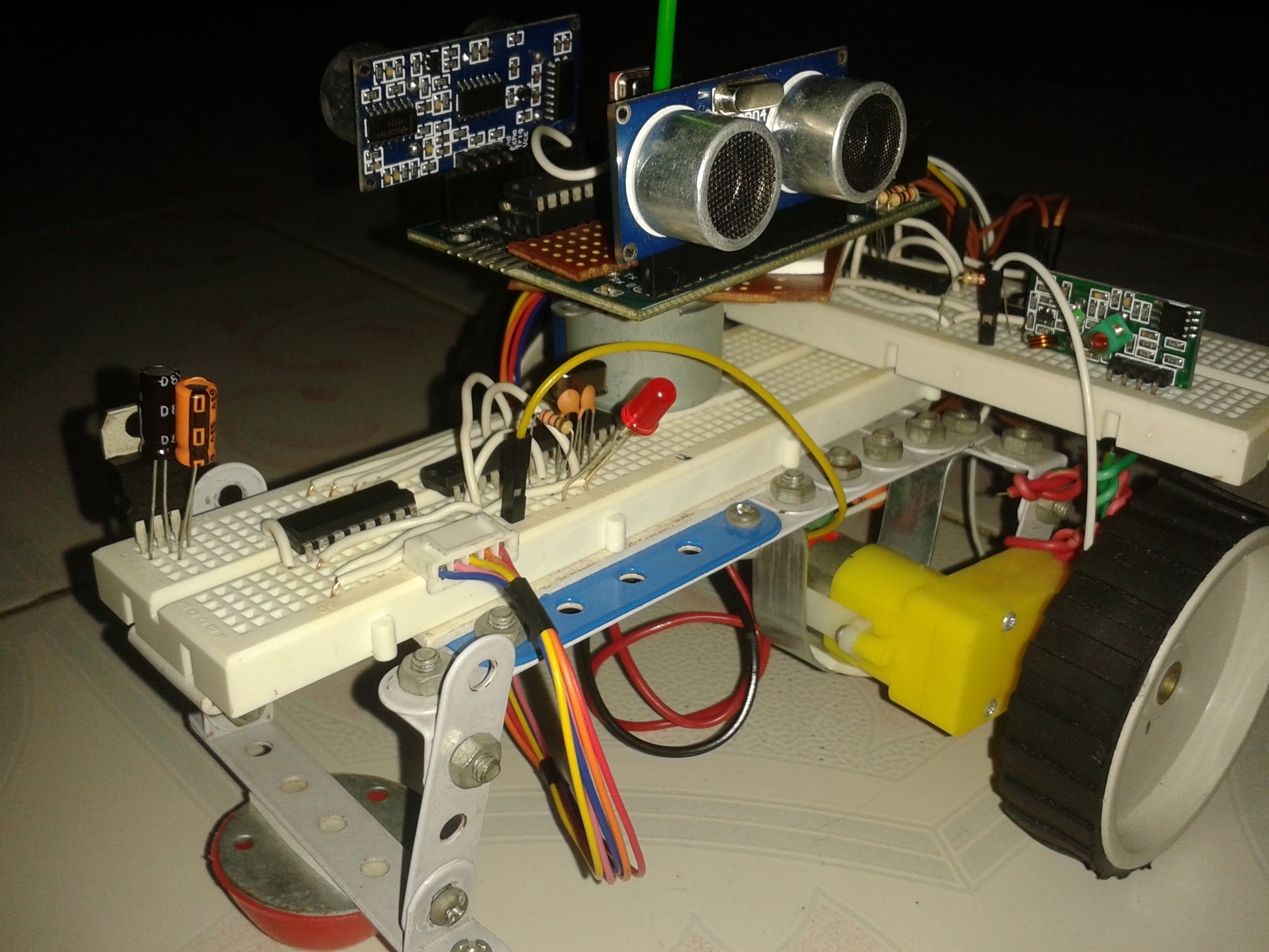
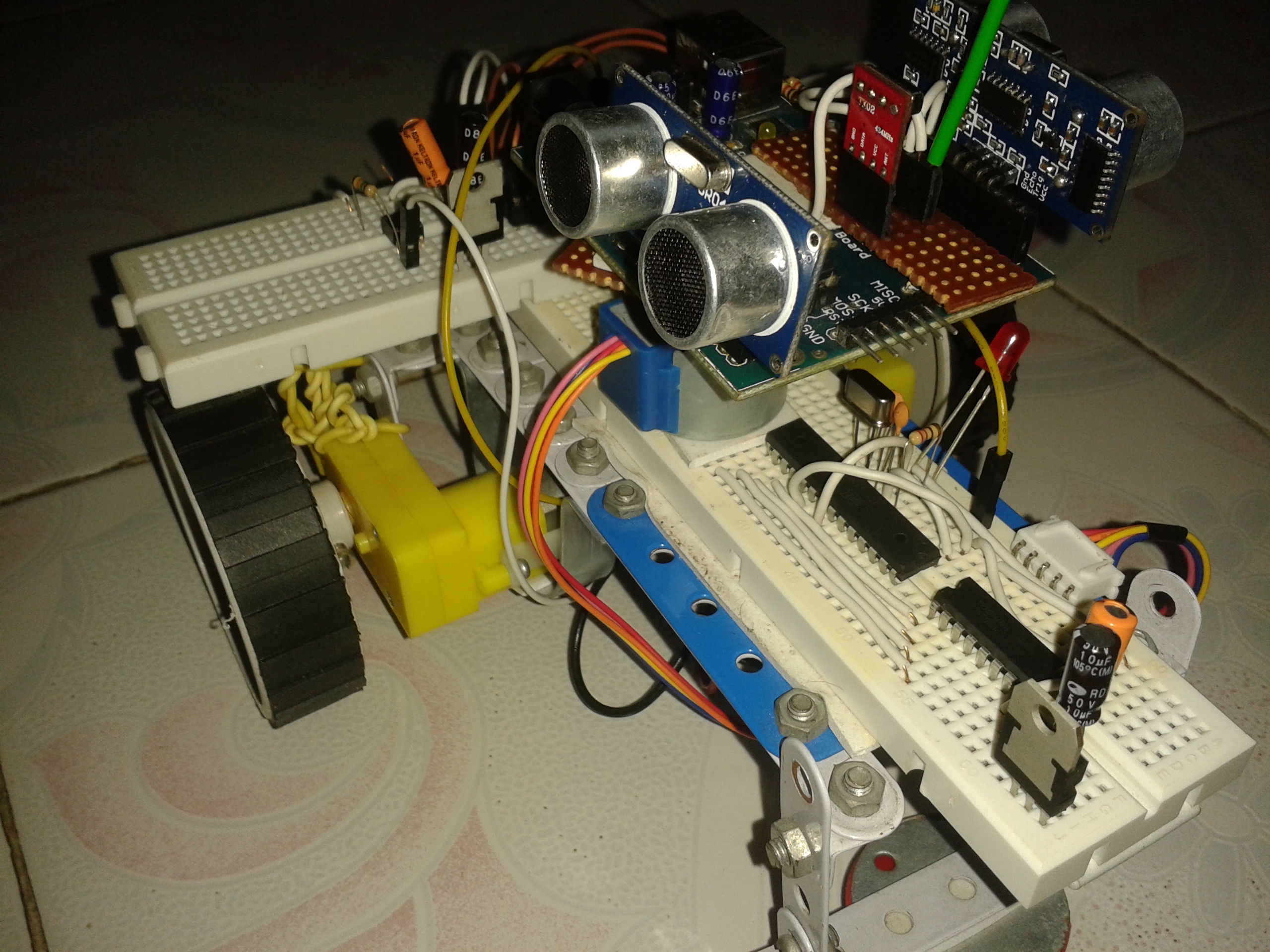
.jpg)
.jpg)
Now its time to do something interesting ; incorporating everything you just learnt in this instructable . i hope it was not much fun till yet , but just hold your thought right there , the real fun is just about to begin.
Warning :- Most of the objectives in and after this Step has to be done solely buy the doer ......very little help from my side
Objective 1 :- To build the chassis.
Things required :-
- Just you imagination , i would not recommend any kind of kit or specific parts, do whatever you want .......borrow,trade,look for useful scraps ........ i will leave the chassis building totally upto you.
What i did :-
My brother had a Zephyr Mechanix it had some random metal bits,strips and planes with nuts and bolts, it was of no use to him, so i borrowed it and made the Chassis as subtle as possible.
Objective 2 :- To fix the 2 X DC Motor and wheel
Things Required :-
- 2 X BO - Offset DC Motor with wheels [ Any motor less than 200 RPM should work just fine]
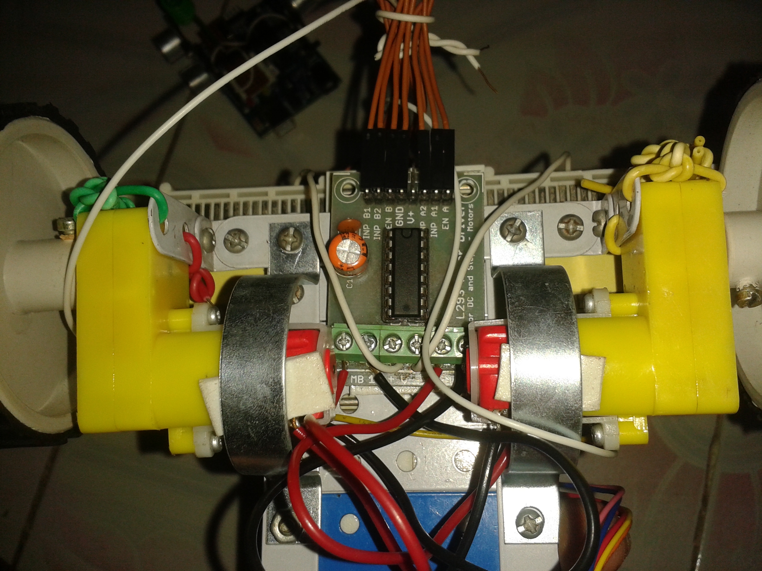
- 1 X L293D Motor Driver module [ if you dont have a module try to make one seeing my schematics ]
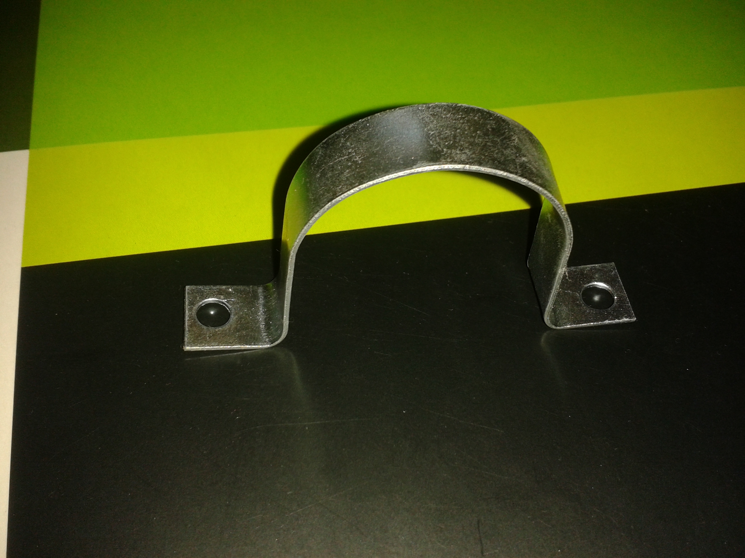
- 2 X U - Motor Clamps
- 2 X Bread Board (If possible take out the two Vcc and gnd lines from them )
- Some nuts and bolts if required
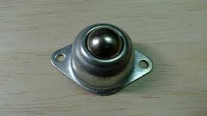
- 1 X Castor Wheel
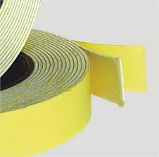
- 1 X Double Sided Foam Tape
- And obviously your intellect
Procedure :-
- Fix the Motor to the desired position.
- Fix the U-Clamp to position the Motor.
- Connect the Motor to the L293d motor driver.
- Stick the two breadboards as neatly and evenly possible to the Chassis using the Tape
- Attach or Stick the Castor Wheel to your preferred position .
Note :- Just remember to have a stable center of gravity.
Objective 3 :- Wiring Everything Up
Things Required :-
- 2 X 5v voltage regulator (L7805)
- 3 X Atmega 328 [ Or what ever 28 pin AVR you have at hand ]
- 2 X 16MHz Crystal Oscillator
- 4 X 22pf Ceramic Capacitors
- 2 X 10 uF Electrolytic Capacitors
- 2 X 1 uF Electrolytic Capacitors
- 1 X ULN 2003 Transistor Array
- 1 X 220 ohm resistor
- 1 X Red LED
- 2 X 1k ohm resistor [ Anything more than 1 k should do just fine ]
- 1 X RF - RX and TX module
- 1 X Stepper Motor with a platform on it.
- 1 X Double Sided Foam Tape
- 2 X Push Button Swicth
- Many small wires
- Some Jumper wires
Procedure :-
1. Recall everything you learned in all the past Steps.
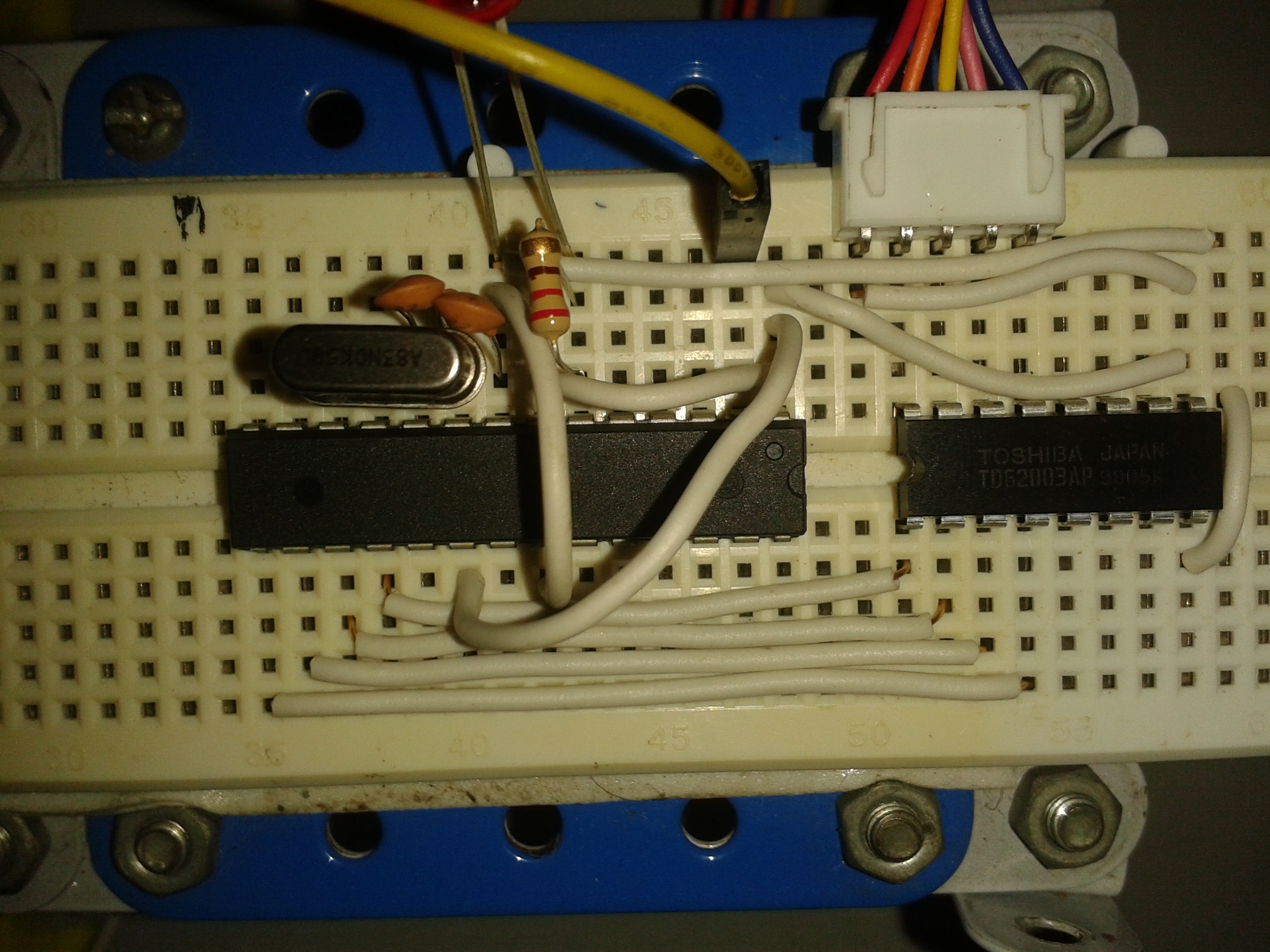
2. Check out first picture thoroughly to understand JAAR's concept then all the wiring will be pieces of a cake.(coz there's not just a single piece).
3. Return to the steps which you have forgotten or need to recall, there's nothing unknown in this circuitry if you have sincerely followed every STEP of this instructable .
3, There are mane images uploaded with tags which clearly portray every connections check them out for any assistance.
4. Cross - check every wiring at least 10 times , coz a single faulty wire could compromise your Atmega (talking form experience ) . this step is the most important of all
Inference :- Guess what, this instructable has almost come to its finish line , everything is ready ....and good to go move on to the next step for some serious coding.
Integrating the Sketches - Part 1(Atmega 1)


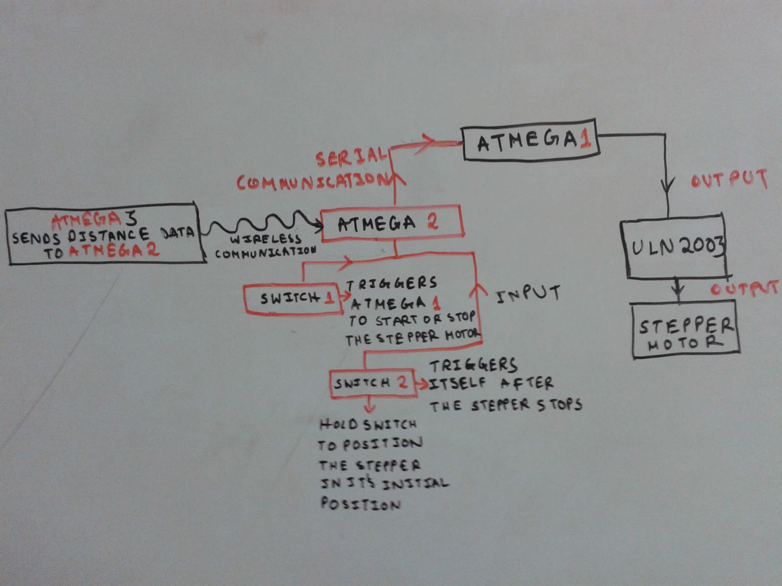
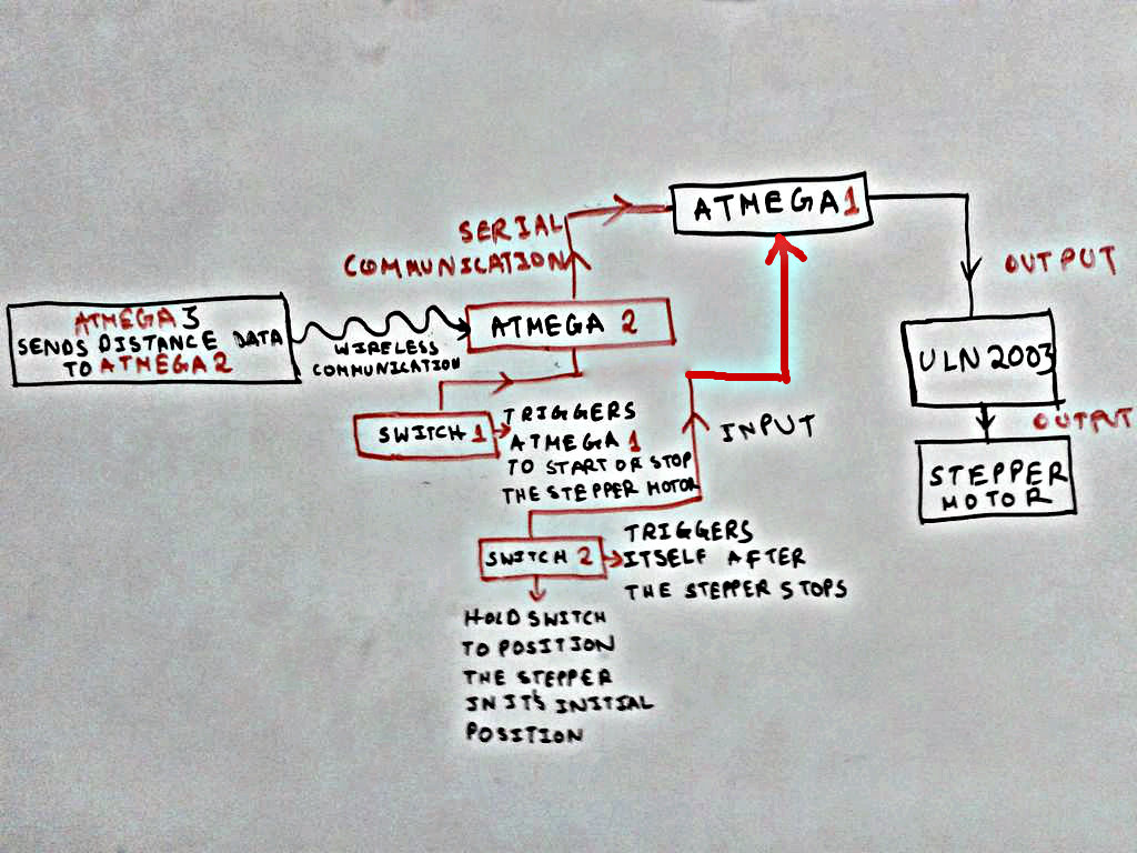
This Step is specifically for the Atmega 1 which will control the Stepper Motor only Every Sketch you went through , all of them are applied and divided into 3 microcontrollers , to do some specific tasks . Please follow the 1st diagram. Its the most important diagram of all.
The function millis(); does all the magic. Go to help>Reference >millis() , to know more about it.
Note :- The steps can turn out to be messy, just be calm, and if you have followed all the steps , the coding will not turn up to be complicated.
Objective 1 :- To keep the track of the real time required for the stepper to rotate once
Things Required :-
- 1 X Arduino UNO or whatever with Atmega and a USB connected to the computer
- Some basic mathematics required like unitary method and distance = speed / time ......very simple
Note :- for this particular task the microcontroller only gives OUTPUT so its not required to connect it to the ULN 2003 or the Stepper Motor and the input which is required from Atmega 2 to initiate itself is directly initialized in the sketch named ATMEGA_1_test .txt.
Procedure :-
- Open the Sketch in IDE Analyze it very nicely. its very simple, there are many unwanted function and lines commented out which may seem a bit confusing but trust me when i tell you that the final sketch that will be uploaded to ATMEGA 1 will have every unwanted lines
- Upload the Sketch
- Quickly Open the Serial Monitor and uncheck the AutoScroll and check that the baud rate is set to 4800 in the down - right corner .
- Then Unplug the USB.
- Close the Serial Monitor.[But do not close the Arduino IDE]
- Plug the USB again
- Wait for few seconds for the IDE to detect the COM port again
- Then press Shift+Ctrl+M.
- You will see after some time numerous values appears one by one.
- We just need the first reading . That's the time taken by the Atmega to rotate the stepper from 0 - 4096 (one rotation), The reading should be 5150 , i.e 5150 milli second to rotate once
What we can see from the Sketch :-
- max speed = 1000 steps/sec
- max acceleration = 1000 steps/sec
- speed = 1000 steps/sec.
- moves to (distance) = 0 - 4096 step [1 rotation]
Questions raised :-
- time = distance/speed = 4096 / 1000 = 4.096 secs for one rotation........but from the Serial monitor we got 5.150 secs HOW ?
Answer :-
There are many lines of code which needs to execute not just the run() function in the Sketch the while loops the if statements variables assigning and many more stuff , So the extra time required is for them to execute.......
Speed Changed :-
Initially the speed was set to 1000 steps / sec in the Sketch , but as per the Serial Monitor data the Time Spent for one rotation in 5.150 secs but the distance to be covered is the same i.e from 0-4096 step
Therefore,
time = 5.150 sec ; steps to be covered (distance) = 4096 steps
Speed = distance / time = 795.34 steps / sec
See, from 1000 steps / secs it came down to 795.34 steps / sec
Realization :-
Imagine what would have happened if you would have used 4.096 secs instead of 5.150 to sync the Proximity Sensors to send data to ATMEGA 2...It would be a blunder the robot would act like a mad person .
Objective 2 :- To Upload the real Sketch to the Atmega 1 .
Things Required :-
- Just the same requirements.
Procedure :-
- Upload the code , after altering or changing the pin configuration if required , and plzz read the comments , i have worked a lot to make simpler comments as far possible
- Plzz understand the program first, thats more important than running it successfully
- Unplug the USB
- Extract the Atmega 1 out , at the back of the Atmega write up ATMEGA -1
- Fix the Atmega 1 to your desired position.
- Check all the connections once again.....
Inference :- Understood how important is it to calculate the program's run time. The time 5.150 secs per rotation will be of a great importance to the next STEP
Move on to the next step to program the Atmega 3 for wireless data transmission ...... i hope you all enjoyed....
Integrating the Sketches - Part 2(Atmega 3)


As the title suggests this step is for Atmega 3 as mentioned in the first diagram.......This step will be more or less similar to the previous step . Lets GO
Objective 1 :- To count the time required...... for the wireless TX module to send 64 distance data from each sensor to the Atmega 2........and also make use of the previous time reading i.e. 5.150 secs .
Things Required :-
- All the stuff you required in Objective 1 of STEP 3.
Procedure :-
- Just put everything together just like its shown in the 2nd image.
- Connect the USB to the Computer.
- Copy the code from ATMEGA_3_test .txt to the IDE and analyze for some time .......you will see most of the code is copied form STEP 3 and not much added to it.
- Upload the code
- Press Ctrl +Shift +M
- Note the reading in the Serial monitor
- Press the reset button in Arduino. Another reading will pop up in the Serial Monitor
- Do it for atleast 10 times.
- You will see most of the run time values are different .
- Make a average and note it down . i got 4058 milli second. Which means to ping and send the wireless data to Atmega 2 its takes 4058 ms without and manual delay. But remember you need the time to be 5150 ms from the previous step
- Therefore , extra time to delay per rotation = 5150-4058 = 1092 ms time to delay per 64 steps = 1092 / 64 = 17.0625 = 17 ms
- See your own reading and follow procedure no. 11
- Open the ATMEGA_3_test in the IDE, at the end of the test() function a delay(17); line is commented
- Uncomment that line and put your deduced value in it
- Upload the changed program .
- Ctrl+Shift+M
- Check if the value printed is close to 5150 or not, if not don't be disheartened its the best which can be done , not your fault, its due to the principles of sound propagation.
- Figure out the problem and comment it here.
Objective 2 :- To Upload the real Sketch
Things Required :-
- Same as above
Procedure :-
- Just Upload the ATMEGA_3 .txt .
- Extract the Atmega 3 out of the Arduino and name it ATMEGA - 3
- Forgot to tell you to Unplug the USB , i hope you are not as dummy.
- Inference :- After seeing a ridiculous behavior of the distance sensor you must be pissed This problem is discussed in the 13th STEP, How to deal with it and stuff.
Next up the Last Step , After the next next step your robot will transform to a Rover .
Guys and gals plzz feel free to post any suggestion about how to deal with this problem and help me make improve this instructable
Integrating the Sketches - Part 3(Atmega 2)

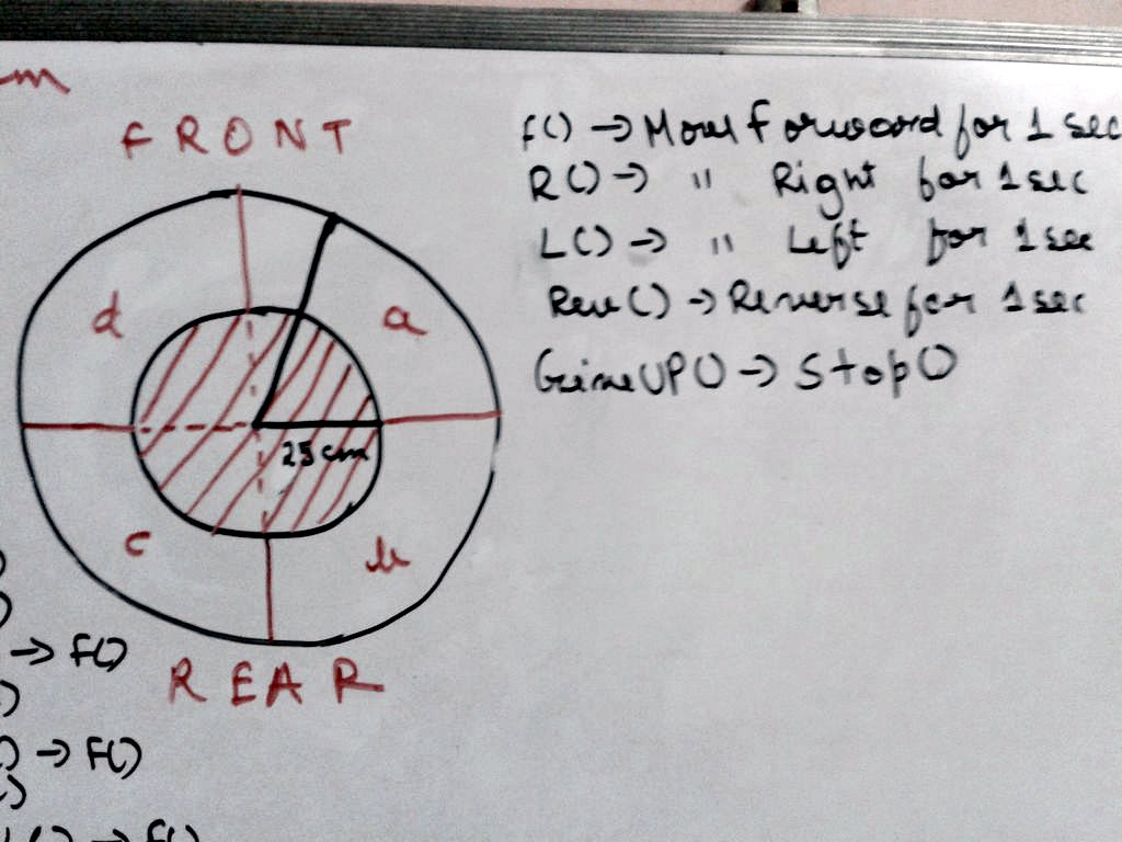
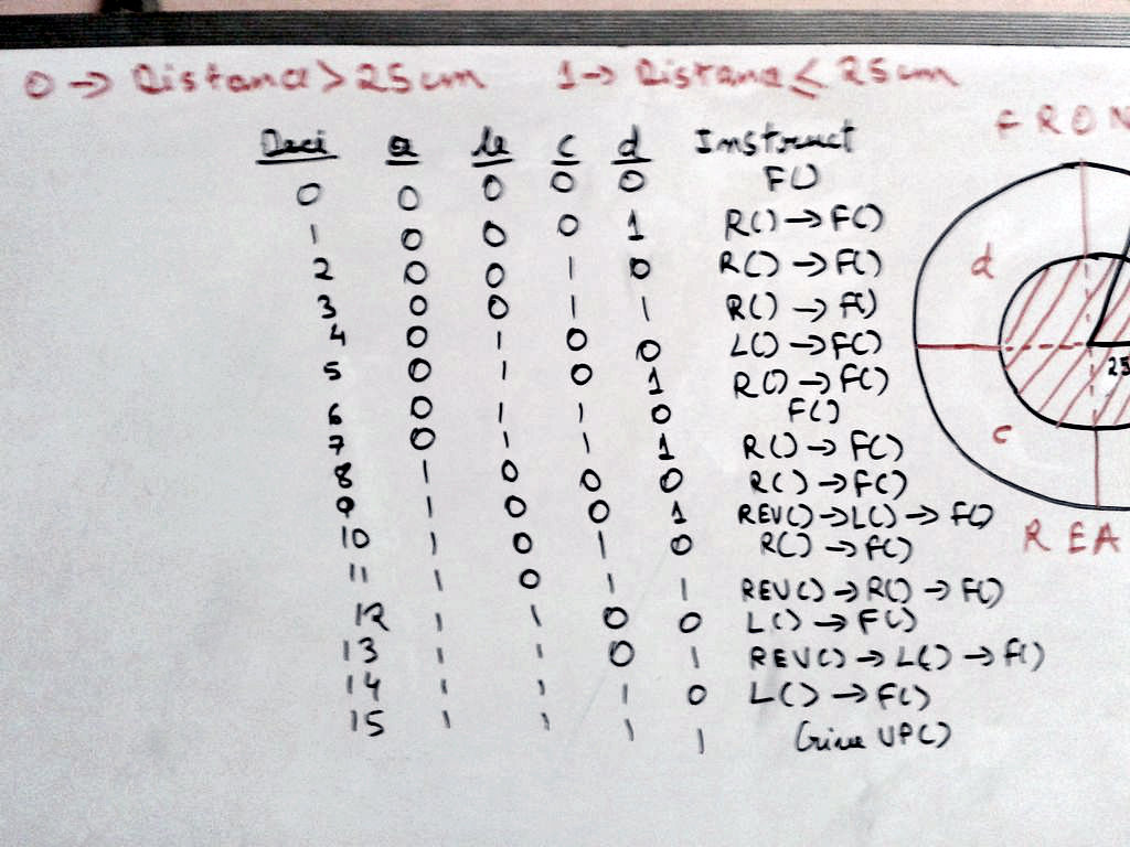
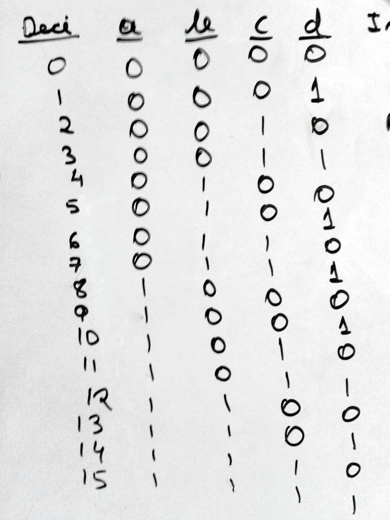
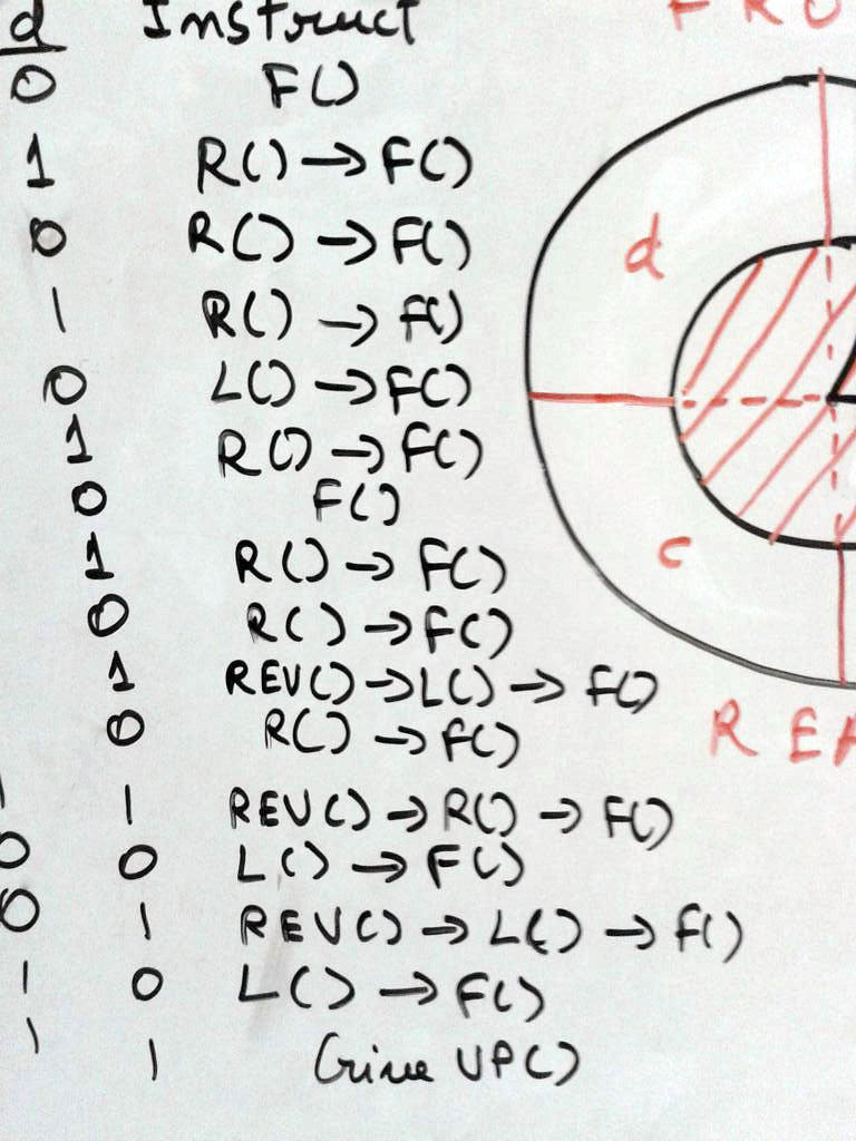


From the first image it is clearly visible that Atmega 2 works somewhat like a Mother micro-controller , it receives input from Atmega 3 , provides output to the the DC Motor interpreting the distance data, triggers the stepper motor to start or stop for adjustments. This is the sole reason why Atmega 2 is described in this last STEP about JAAR. There's no test program for this step......coz no delay() adjustments can be made, coz its the mother micro-controller. So whatever time it needs cannot be changed (possible if more easier algorithms are developed )
Objective 1:- To Program the Mother micro-controller
Things Required :-
- Just a UNO or whatever with a Atmega 328 on it
- USB Cable, thats obvious.
Procedure :-
- I hope you have got the first image has become very clear in your mind by now, if not then plzz check it again
- Copy the code ATMEGA_2 .txt to the IDE.
- Minimize the IDE for some time.
- Check the 2nd image.
- See the diagram , there's a shaded portion which is the danger zone with a radius of 25 cm according to my chassis, make changes to the program if you have to.
- The not shaded portion is the safe zone which can have a maximum radius of 200 cm
- See a cross-hair type sign inside the circle, that actually means that i have divided the area into four parts a, b, c,d respectively, to detect where the obstacles are in real time.
- At the right corner of the second image is the definition of 5 functions used in the algorithm.
- Understand , How its gonna happen.
- Take a look at the 3rd image .
- There's a 4 variable (a,b,c,d) binary combination table, '1' denotes that the distance is less than 25 (i.e. in danger zone) and the '0' signifies the distance is greater than 25 (i.e. in safe zone).
- See there's also a output variable named 'Instruct' which calls different functions for different combinations.
- Check both image 2 and 3 simultaneously to check the whether all the function call for a specific situation is appropriate or not . If there's something wrong you feel, plzz post a comment about it here.
- But see there's two steps which you can cancel out in your program, inform me after you find it..
- Now you r ready to upload the code , So Upload it to the Atmega.
- Unplug the Arduino and extract the Atmega out of it and name it ATMEGA -2
- Fix the Atmega to your appropriate place.
- And you are ready to go. Just power everything ( i used a 3S1P Lipo for Atmega 2 and Atmega 2 and a common 9v transistor battery to power the Atmega 3).
- Play around with it , sometimes it can behave oddly(its mostly due to the distance sensor, cant help it), whenever it does so , disconnect the power and connect it back again , and dont forget to adjust to stepper facing front.
- Comment about you experience
Inference :-
Asta la vista to programming for now, i think you r ready to make the rover move. Play fool with it for some time .
Here Endeth , the next two steps is about the problems with HC-SR04 and what i am going to do next.
Plzz feel free to inform me about the problems which came up while finishing this huge project (at least to me), or you could just google it simply, google has answer to everything.
Downloads
The Problem With HC-SR04

To those who have done it or read everything i wrote , its evident that the rover will be a failure many a times , and most of it is because of the Ultrasonic Distance Sensors used .
Problem with Ultrasonic Distance Sensors :-
1. Sound changes speed relative to Temperature, Humidity and Density (Sound travels 4.3 times faster in water) but we cannot execute experiments under water, you know what will happen.
2. These sensors require quite a fair amount of area to actually detect an obstacle ,its due to absorbing and reflective property of sound while collision.
3, Farther the object from the sensor , more time it takes to calculate the distance (its a long process, sound gets emitted out then reflected by the target object them the wave comes and hits the receiver), So it takes time for long distances.
4. And i think there are many more disadvantages to use sound in obstacle detection, which i am not aware of right now. Plzz comment and mention any that you are aware of.
Thus, using the ultrasonic distance sensor was a blunder , but we also need to improve right ........So if any one has any idea about about how to TroubleShoot this huge problem, plzz feel free to post it here. i would love see and share new ideas...........
Whatever it is ....i think you all had fun , coz starting from debouncing a switch you came up with an Obstacle Avoiding Rover , thats a huge progress within just 1 instructable.
Always Remember basics should be the first priority , and that was my primary goal from the beginning
My Moto :- Know What you don't Know
What's Coming Next..........
.jpg)
This was my first instructable ever , so tried to make it as simple as possible, if anyone has any kind of doubts or suggestion plzz feel free to contact me...........
As you can see i have started , so be ready for more.
Firstly, i will post a video of JAAR moving about .
Secondly,
i will also add another instructable in which i will show how to display the SONAR map graphically in your PC or Mac with a small tutorial of Processing , Processing coz its heavily based on Arduino IDE.
Thirdly,
I will Post another instructable , which will be about how to improve the distance measuring technique , using a 650 nm LASER and a low contrast camera(OV 7670 maybe), i dont think it will be evident for an Arduino to handle image processing fast enough, but try though, but there's 80% chances that i will use a Raspberry.
Bye fellas see you all later, Hope you had fun................